EP0418207A1 - Flüssigkeitspumpe mit flexibler Pumpenkammer - Google Patents
Flüssigkeitspumpe mit flexibler Pumpenkammer Download PDFInfo
- Publication number
- EP0418207A1 EP0418207A1 EP90850307A EP90850307A EP0418207A1 EP 0418207 A1 EP0418207 A1 EP 0418207A1 EP 90850307 A EP90850307 A EP 90850307A EP 90850307 A EP90850307 A EP 90850307A EP 0418207 A1 EP0418207 A1 EP 0418207A1
- Authority
- EP
- European Patent Office
- Prior art keywords
- pump chamber
- outlet
- inlet
- pump
- pressure
- Prior art date
- Legal status (The legal status is an assumption and is not a legal conclusion. Google has not performed a legal analysis and makes no representation as to the accuracy of the status listed.)
- Granted
Links
- 239000012530 fluid Substances 0.000 title claims abstract description 15
- 210000004369 blood Anatomy 0.000 claims abstract description 39
- 239000008280 blood Substances 0.000 claims abstract description 39
- 238000006073 displacement reaction Methods 0.000 claims abstract description 10
- 239000000463 material Substances 0.000 claims abstract description 5
- 230000000737 periodic effect Effects 0.000 claims abstract description 5
- 238000010276 construction Methods 0.000 claims description 5
- 230000006835 compression Effects 0.000 claims description 4
- 238000007906 compression Methods 0.000 claims description 4
- 230000007246 mechanism Effects 0.000 description 14
- 238000005086 pumping Methods 0.000 description 9
- 230000017531 blood circulation Effects 0.000 description 6
- 230000036770 blood supply Effects 0.000 description 6
- 230000002572 peristaltic effect Effects 0.000 description 4
- 210000000601 blood cell Anatomy 0.000 description 3
- 210000004204 blood vessel Anatomy 0.000 description 3
- 230000006378 damage Effects 0.000 description 3
- 230000000541 pulsatile effect Effects 0.000 description 3
- 238000012544 monitoring process Methods 0.000 description 2
- 210000000056 organ Anatomy 0.000 description 2
- 230000010412 perfusion Effects 0.000 description 2
- 206010019280 Heart failures Diseases 0.000 description 1
- 208000013875 Heart injury Diseases 0.000 description 1
- 208000004852 Lung Injury Diseases 0.000 description 1
- 238000004026 adhesive bonding Methods 0.000 description 1
- 230000008901 benefit Effects 0.000 description 1
- 230000036772 blood pressure Effects 0.000 description 1
- 230000008859 change Effects 0.000 description 1
- 230000015271 coagulation Effects 0.000 description 1
- 238000005345 coagulation Methods 0.000 description 1
- 238000000502 dialysis Methods 0.000 description 1
- 230000003205 diastolic effect Effects 0.000 description 1
- 238000011038 discontinuous diafiltration by volume reduction Methods 0.000 description 1
- 230000005484 gravity Effects 0.000 description 1
- 230000001771 impaired effect Effects 0.000 description 1
- 238000000338 in vitro Methods 0.000 description 1
- 230000004199 lung function Effects 0.000 description 1
- 231100000515 lung injury Toxicity 0.000 description 1
- 230000007257 malfunction Effects 0.000 description 1
- 238000012986 modification Methods 0.000 description 1
- 230000004048 modification Effects 0.000 description 1
- 238000006213 oxygenation reaction Methods 0.000 description 1
- 230000002040 relaxant effect Effects 0.000 description 1
- 238000007789 sealing Methods 0.000 description 1
- 238000001356 surgical procedure Methods 0.000 description 1
- 238000003466 welding Methods 0.000 description 1
Images

Classifications
-
- A—HUMAN NECESSITIES
- A61—MEDICAL OR VETERINARY SCIENCE; HYGIENE
- A61M—DEVICES FOR INTRODUCING MEDIA INTO, OR ONTO, THE BODY; DEVICES FOR TRANSDUCING BODY MEDIA OR FOR TAKING MEDIA FROM THE BODY; DEVICES FOR PRODUCING OR ENDING SLEEP OR STUPOR
- A61M60/00—Blood pumps; Devices for mechanical circulatory actuation; Balloon pumps for circulatory assistance
- A61M60/10—Location thereof with respect to the patient's body
- A61M60/104—Extracorporeal pumps, i.e. the blood being pumped outside the patient's body
- A61M60/109—Extracorporeal pumps, i.e. the blood being pumped outside the patient's body incorporated within extracorporeal blood circuits or systems
- A61M60/113—Extracorporeal pumps, i.e. the blood being pumped outside the patient's body incorporated within extracorporeal blood circuits or systems in other functional devices, e.g. dialysers or heart-lung machines
-
- A—HUMAN NECESSITIES
- A61—MEDICAL OR VETERINARY SCIENCE; HYGIENE
- A61M—DEVICES FOR INTRODUCING MEDIA INTO, OR ONTO, THE BODY; DEVICES FOR TRANSDUCING BODY MEDIA OR FOR TAKING MEDIA FROM THE BODY; DEVICES FOR PRODUCING OR ENDING SLEEP OR STUPOR
- A61M60/00—Blood pumps; Devices for mechanical circulatory actuation; Balloon pumps for circulatory assistance
- A61M60/80—Constructional details other than related to driving
- A61M60/855—Constructional details other than related to driving of implantable pumps or pumping devices
- A61M60/89—Valves
- A61M60/894—Passive valves, i.e. valves actuated by the blood
-
- A—HUMAN NECESSITIES
- A61—MEDICAL OR VETERINARY SCIENCE; HYGIENE
- A61M—DEVICES FOR INTRODUCING MEDIA INTO, OR ONTO, THE BODY; DEVICES FOR TRANSDUCING BODY MEDIA OR FOR TAKING MEDIA FROM THE BODY; DEVICES FOR PRODUCING OR ENDING SLEEP OR STUPOR
- A61M60/00—Blood pumps; Devices for mechanical circulatory actuation; Balloon pumps for circulatory assistance
- A61M60/10—Location thereof with respect to the patient's body
- A61M60/104—Extracorporeal pumps, i.e. the blood being pumped outside the patient's body
- A61M60/109—Extracorporeal pumps, i.e. the blood being pumped outside the patient's body incorporated within extracorporeal blood circuits or systems
-
- A—HUMAN NECESSITIES
- A61—MEDICAL OR VETERINARY SCIENCE; HYGIENE
- A61M—DEVICES FOR INTRODUCING MEDIA INTO, OR ONTO, THE BODY; DEVICES FOR TRANSDUCING BODY MEDIA OR FOR TAKING MEDIA FROM THE BODY; DEVICES FOR PRODUCING OR ENDING SLEEP OR STUPOR
- A61M60/00—Blood pumps; Devices for mechanical circulatory actuation; Balloon pumps for circulatory assistance
- A61M60/10—Location thereof with respect to the patient's body
- A61M60/104—Extracorporeal pumps, i.e. the blood being pumped outside the patient's body
- A61M60/117—Extracorporeal pumps, i.e. the blood being pumped outside the patient's body for assisting the heart, e.g. transcutaneous or external ventricular assist devices
-
- A—HUMAN NECESSITIES
- A61—MEDICAL OR VETERINARY SCIENCE; HYGIENE
- A61M—DEVICES FOR INTRODUCING MEDIA INTO, OR ONTO, THE BODY; DEVICES FOR TRANSDUCING BODY MEDIA OR FOR TAKING MEDIA FROM THE BODY; DEVICES FOR PRODUCING OR ENDING SLEEP OR STUPOR
- A61M60/00—Blood pumps; Devices for mechanical circulatory actuation; Balloon pumps for circulatory assistance
- A61M60/10—Location thereof with respect to the patient's body
- A61M60/122—Implantable pumps or pumping devices, i.e. the blood being pumped inside the patient's body
-
- A—HUMAN NECESSITIES
- A61—MEDICAL OR VETERINARY SCIENCE; HYGIENE
- A61M—DEVICES FOR INTRODUCING MEDIA INTO, OR ONTO, THE BODY; DEVICES FOR TRANSDUCING BODY MEDIA OR FOR TAKING MEDIA FROM THE BODY; DEVICES FOR PRODUCING OR ENDING SLEEP OR STUPOR
- A61M60/00—Blood pumps; Devices for mechanical circulatory actuation; Balloon pumps for circulatory assistance
- A61M60/30—Medical purposes thereof other than the enhancement of the cardiac output
- A61M60/31—Medical purposes thereof other than the enhancement of the cardiac output for enhancement of in vivo organ perfusion, e.g. retroperfusion
-
- A—HUMAN NECESSITIES
- A61—MEDICAL OR VETERINARY SCIENCE; HYGIENE
- A61M—DEVICES FOR INTRODUCING MEDIA INTO, OR ONTO, THE BODY; DEVICES FOR TRANSDUCING BODY MEDIA OR FOR TAKING MEDIA FROM THE BODY; DEVICES FOR PRODUCING OR ENDING SLEEP OR STUPOR
- A61M60/00—Blood pumps; Devices for mechanical circulatory actuation; Balloon pumps for circulatory assistance
- A61M60/30—Medical purposes thereof other than the enhancement of the cardiac output
- A61M60/36—Medical purposes thereof other than the enhancement of the cardiac output for specific blood treatment; for specific therapy
- A61M60/37—Haemodialysis, haemofiltration or diafiltration
-
- A—HUMAN NECESSITIES
- A61—MEDICAL OR VETERINARY SCIENCE; HYGIENE
- A61M—DEVICES FOR INTRODUCING MEDIA INTO, OR ONTO, THE BODY; DEVICES FOR TRANSDUCING BODY MEDIA OR FOR TAKING MEDIA FROM THE BODY; DEVICES FOR PRODUCING OR ENDING SLEEP OR STUPOR
- A61M60/00—Blood pumps; Devices for mechanical circulatory actuation; Balloon pumps for circulatory assistance
- A61M60/30—Medical purposes thereof other than the enhancement of the cardiac output
- A61M60/36—Medical purposes thereof other than the enhancement of the cardiac output for specific blood treatment; for specific therapy
- A61M60/38—Blood oxygenation
-
- A—HUMAN NECESSITIES
- A61—MEDICAL OR VETERINARY SCIENCE; HYGIENE
- A61M—DEVICES FOR INTRODUCING MEDIA INTO, OR ONTO, THE BODY; DEVICES FOR TRANSDUCING BODY MEDIA OR FOR TAKING MEDIA FROM THE BODY; DEVICES FOR PRODUCING OR ENDING SLEEP OR STUPOR
- A61M60/00—Blood pumps; Devices for mechanical circulatory actuation; Balloon pumps for circulatory assistance
- A61M60/40—Details relating to driving
- A61M60/424—Details relating to driving for positive displacement blood pumps
- A61M60/438—Details relating to driving for positive displacement blood pumps the force acting on the blood contacting member being mechanical
- A61M60/441—Details relating to driving for positive displacement blood pumps the force acting on the blood contacting member being mechanical generated by an electromotor
-
- A—HUMAN NECESSITIES
- A61—MEDICAL OR VETERINARY SCIENCE; HYGIENE
- A61M—DEVICES FOR INTRODUCING MEDIA INTO, OR ONTO, THE BODY; DEVICES FOR TRANSDUCING BODY MEDIA OR FOR TAKING MEDIA FROM THE BODY; DEVICES FOR PRODUCING OR ENDING SLEEP OR STUPOR
- A61M60/00—Blood pumps; Devices for mechanical circulatory actuation; Balloon pumps for circulatory assistance
- A61M60/80—Constructional details other than related to driving
- A61M60/835—Constructional details other than related to driving of positive displacement blood pumps
- A61M60/837—Aspects of flexible displacement members, e.g. shapes or materials
-
- A—HUMAN NECESSITIES
- A61—MEDICAL OR VETERINARY SCIENCE; HYGIENE
- A61M—DEVICES FOR INTRODUCING MEDIA INTO, OR ONTO, THE BODY; DEVICES FOR TRANSDUCING BODY MEDIA OR FOR TAKING MEDIA FROM THE BODY; DEVICES FOR PRODUCING OR ENDING SLEEP OR STUPOR
- A61M60/00—Blood pumps; Devices for mechanical circulatory actuation; Balloon pumps for circulatory assistance
- A61M60/80—Constructional details other than related to driving
- A61M60/845—Constructional details other than related to driving of extracorporeal blood pumps
- A61M60/851—Valves
-
- A—HUMAN NECESSITIES
- A61—MEDICAL OR VETERINARY SCIENCE; HYGIENE
- A61M—DEVICES FOR INTRODUCING MEDIA INTO, OR ONTO, THE BODY; DEVICES FOR TRANSDUCING BODY MEDIA OR FOR TAKING MEDIA FROM THE BODY; DEVICES FOR PRODUCING OR ENDING SLEEP OR STUPOR
- A61M60/00—Blood pumps; Devices for mechanical circulatory actuation; Balloon pumps for circulatory assistance
- A61M60/10—Location thereof with respect to the patient's body
- A61M60/122—Implantable pumps or pumping devices, i.e. the blood being pumped inside the patient's body
- A61M60/196—Implantable pumps or pumping devices, i.e. the blood being pumped inside the patient's body replacing the entire heart, e.g. total artificial hearts [TAH]
-
- A—HUMAN NECESSITIES
- A61—MEDICAL OR VETERINARY SCIENCE; HYGIENE
- A61M—DEVICES FOR INTRODUCING MEDIA INTO, OR ONTO, THE BODY; DEVICES FOR TRANSDUCING BODY MEDIA OR FOR TAKING MEDIA FROM THE BODY; DEVICES FOR PRODUCING OR ENDING SLEEP OR STUPOR
- A61M60/00—Blood pumps; Devices for mechanical circulatory actuation; Balloon pumps for circulatory assistance
- A61M60/80—Constructional details other than related to driving
- A61M60/855—Constructional details other than related to driving of implantable pumps or pumping devices
- A61M60/89—Valves
- A61M60/892—Active valves, i.e. actuated by an external force
Definitions
- the present invention relates to an improved fluid pump, particularly for connection to the blood circulatory system of a living being.
- the pump according to the invention has thus primarily been developed for use as an extracorporeal blood pump in conjunction, for instance, with surgical operations, dialysis, oxygenation of the blood in patients having an impaired lung function, for circulatory support after a cardiac insufficiency or for victims of accidents with heart or lung injuries, etc. It is also conceivable, however, for a pump according to the invention to be constructed in a manner which would enable it to be implanted in a patient as an artificial heart. It is also possible that a pump according to the invention could be advantageous to use also in other contexts, such as regional organ perfusion and/or organ perfusion in vitro.
- Extracorporeal blood pumps used today for the above mentioned purposes are in the great majority of cases peristaltic so-called roller pumps, in which the blood is transported through a tube by rollers compressing the tube and simultaneously moving therealong.
- roller pumps in which the blood is transported through a tube by rollers compressing the tube and simultaneously moving therealong.
- pulsatile pump has also begun to be used to a certain extent for the mentioned purposes, which pump basically consists of a pump bladder with flexible, resilient walls, which bladder has inlets and outlets provided with non-return valves and is enclosed in a surrounding rigid chamber, inside which a periodically varying pressure is generated for alternate compression and expansion of the pump bladder.
- the peristaltic roller pumps have the serious drawback that it is very difficult to avoid considerable damages to the blood corpuscles in the pumped blood in consequence of the squeeze and shear forces that the blood corpuscles are subjected to in the pump.
- the peristaltic roller pumps as well as the pulsatile pumps of the above mentioned type also have the common drawback that the operation of the pump will cause considerable subpressures at the inlet of the pump, and also in the pump bladder in the case of the pulsatile pump, if the inflow of blood to the pump inlet does not correspond to the nominal pumped flow of the pump but falls below it.
- Such a situation is liable to occur with relative ease, for example as a result of a blockage at the end of the catheter connecting the pump to a blood vessel, for instance by abutment of the catheter end with the wall of the blood vessel.
- the subpressure which in the hitherto used pumps in such cases is automatically generated on the inlet side of the pump and in the pump bladder may give rise to very troublesome problems.
- the subpressure may cause serious mechanical damages to the patient's blood vessels. Further, the subpressure may cause air to leak into the pump system through untight connections between various parts of the pump system, and if the subpressure is sufficient it may also result in gas being released from the pumped blood. In both cases serious gas emboli may occur.
- the prior art blood pumps of the type discussed it is therefore necessary to monitor the pressure prevailing on the inlet side of the pump and in case of a subpressure intervene into the operation of the pump such that no serious situation may arise. Such a monitoring and control system will, of course, complicate and raise the price of the pump and will in itself constitute an additional source of possible malfunctions.
- the present invention thus relates to a fluid pump, particularly for connection to the blood circulatory system of a living being, of a type comprising a pump chamber having an inlet opening at one end and an outlet opening at the opposite end.
- a first non-return valve is connected to the inlet opening and permits a fluid flow only in the direction into the pump chamber through the inlet opening
- a second non-return valve is connected to the outlet opening and permits a fluid flow only in the direction out from the pump chamber through the outlet opening.
- the inlet and the outlet are movable in relation to each other in the direction of the pump chamber extension between the inlet and the outlet and are connected to controllable drive means for periodic displacement thereof alternately towards and away from each other in said direction of extension, the interior volume existing in the pump chamber between the inlet and outlet being variable in correspondence with the relative distance between them in said direction of extension.
- such a pump may readily be constructed such that no mechanical damages will occur to the blood corpuscles in the pumped blood.
- the present invention is further based upon the discovery that in such a pump it is possible to automatically ensure, without any particular monitoring and control system, that no subpressure can be generated at the pump inlet or in the pump itself.
- a fluid pump of the above described type such that the pump chamber on the outside thereof is acted upon by the surrounding pressure (which e.g. may be the atmospheric pressure or the ambient pressure in a pressure chamber if the patient is subjected to such treatment), that it has a wall at least partially of a flexible material, and that it under the influence of a pressure difference, which is caused by the surrounding pressure exceeding the interior pressure of the pump chamber and which is greater than the required opening pressure difference for the first non-return valve connected to the inlet, is collapsible in a controlled manner by a volume at least corresponding to the maximum increase of said interior volume of the pump chamber when the inlet and the outlet are moved away from each other.
- the surrounding pressure which e.g. may be the atmospheric pressure or the ambient pressure in a pressure chamber if the patient is subjected to such treatment
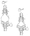
- the pump according to the invention illustrated schematically and by way of example in Figs. 1 and 2 comprises a pump chamber 1 having an inlet 2 and an outlet 3 situated opposite to the inlet 2.
- Non-return valves 4 and 5 are connected to the inlet 2 and outlet 3, respectively, e.g. by gluing or ultrasonic welding, or by the valves being integral with the pump chamber.
- the valves 4 and 5 may, of course, be connected to the the respective inlet by any other suitable means, such as, for example, a mechanical compression type connection or the like.
- the two valves are arranged such that the inlet valve 4 only permits a flow into the pump chamber 1, while the outlet valve only permits a flow out from the pump chamber 1.
- the two non-return valves consist, as schematically shown, of movable valve bodies, which are acted upon by a closing force in a direction to sealing abutment against an associated valve seat, which closing force thus must be overcome for the valve to open.
- the closing force acting upon the valve body may, for example, consist of a spring force or of the weight of the valve body if the latter has a higher density than the pumped blood fluid, or as in the illustrated embodiment of the boyancy of the valve body in the pumped blood fluid as a result of the valve body having a lower density than the pumped blood fluid, or, finally, simply result from the blood pressure on the valves in the flow direction during the systolic (compression) and diastolic (relaxing) periods, respectively.
- the inlet 2 with the inlet valve 4 is stationarily arranged in an immobile holder 4a, while the outlet 3 with the outlet valve 5 is arranged in a holder 5a which is reciprocatable in the longitudinal direction of the pump chamber 1, as is indicated by an arrow 7, when driven by a drive unit 6, constructed in a suitable manner, which is only indicated schematically and not shown in any detail.
- the pump chamber 1 is constructed as a substantially spherical bladder having flexible walls, which bladder, as will be described in more detail below, is constructed in such a manner as to enable part of its wall to be folded telescopically from the state shown im Fig. 1 to the state shown in Fig.
- the volume of the pump chamber is reduced so that blood is pressed out through the outlet valve 5 to the outlet tube 9 connected to the patient's blood circulatory system.
- the blood volume pumped per unit of time may be determined and varied, respectively, by means of the frequency of the reciprocating movement of the outlet 3 and/or by the magnitude of the distance of movement of the outlet 3. It will also be appreciated that exactly the same function may be obtained by holding the outlet 3 stationary while periodically reciprocating the inlet 2 in the axial direction of the pump chamber 1.
- both the inlet 2 and the outlet 3 may also be periodically reciprocated in the axial direction of the pump chamber 1, enabling the blood volume pumped per unit of time to be varied by changing the relative phase position for these two periodical movements, maximum pumping being obtained when the two movements are in counter-phase, while no pumping at all is obtained when the two movements are in phase with each other.
- the occurrence of such a subpressure is automatically avoided without it being necessary to influence the operation of the pump in any way.
- the pump chamber being constructed in such a manner that it will collapse, i.e. fall together reducing its interior volume, if the pressure prevailing in the pump chamber should fall below the ambient pressure acting upon the outside of the pump chamber with an amount exceeding the pressure difference between the inlet tube 8 and the interior of the pump chamber 1.
- the pump chamber 1 is in that respect constructed in such a way that its possible collapse and resulting volume reduction will be at least as great as the maximum volume increase during a filling stroke, i.e. during the movement of the outlet 3 from the position shown in Fig. 2 to the position shown in Fig. 1.
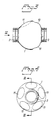
- the pump chamber 1 may advantageously be constructed in the way illustrated in Figs. 3 and 4.
- the advantageous embodiment of a pump chamber illustrated in Figs. 3 and 4 is constructed as a generally spherical bladder having diametrically opposed inlet and outlet connection pieces 2 and 3, respectively, for mounting of the inlet and outlet valves not shown in Figs. 3 and 4.
- the wall of the bladder 1 consists of a flexible but lu substantially non-stretchable material.
- the wall of the bladder 1 On the side of the central diametrical plane between the inlet 2 and the outlet 3 which is situated closest to the outlet 3, the wall of the bladder 1 has an annular portion 10 which is concentric in relation to the centre axis of the bladder and has a substantially reduced wall thickness and a configuration slightly deviating from the spherical configuration in a double-wavy manner.
- the wall 1 of the bladder may be folded in telescopically in the manner shown in Fig. 2 in the course of the reciprocating movement of the outlet 3, without the configuration of the pump bladder being substantially changed in other respects.
- the wall of the bladder 1 On the opposite side of said central diametrical plane, i.e. closest to the inlet 2, the wall of the bladder 1 is constructed with a number of generally circular portions 11, in the illustrated embodiment five such portions (Fig. 4), having a likewise substantially reduced wall thickness.
- the wall of the pump bladder may easily curve in, i.e. collapse, from the position indicated with a solid line to the position shown with a dashed line in Fig.
- the wall portions 11 are adjusted in such a manner that the decrease of the interior volume of the pump bladder 1 caused by their collapse is at least as great as the maximum increase of the volume of the pump bladder when the outlet 3 moves from the position shown in Fig. 2 to the position shown in Fig. 1, i.e. during a filling stroke for the pump bladder.
- This collapse of the wall portions 11 of the pump bladder does not affect the configuration and function of the pump bladder in other respects.
- the collapsible wall portions may have other configurations and may also be located differently, e.g. in the opposite part of the pump bladder or be distributed over the whole or a major part of the pump bladder.
- non-return valves do not necessarily have to be placed in immediate connection to the inlet and outlet, respectively, of the pump chamber, but could also be arranged at a distance from the pump chamber, for example in the inlet tube 8 and the outlet tube 9, respectively.
- the drive means is constructed so as to additionally ensure that no unpermissible overpressure can be generated at the pump outlet or in the pump itself.
- a drive means arrangement which prevents both unpermissible overpressures and unpermissible subpressures (by other means than a collapsible pump chamber) is described in our patent application entitled “Blood pump with associated drive means” and filed simultaneously herewith (the disclosure of which is incorporated by reference herein).
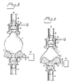
- the combination thereof with the present invention primarily relating to the collapsibility of the pump chamber in a pump of the type in question, is illustrated in Figs. 5 and 6 wherein corresponding parts to those in Figs. 1 to 4 are provided with the same reference numerals.
- the inlet 2 with the inlet valve 4 and the outlet 3 with the outlet valve 5 are reciprocatingly displaceable in relation to each other by a drive means between the most brought apart position illustrated in Fig. 5 and the most brought together position illustrated in Fig. 6.
- the inlet 2 with the inlet valve 4 is arranged in an annular holder 12 which is stationarily mounted in a suitable manner not shown in any detail.
- the inlet 2 with the inlet valve 4 is axially movable in relation to the holder 12 through a limited distance corresponding to the length of the maximum desired relative movement between the inlet 2 and the outlet 3.
- a spring means 13 is arranged between the holder 12 and the inlet 2 with the inlet valve 4.
- the outlet 3 with the outlet valve 5 is similarly arranged in an annular holder 14 and is axially movable in relation to this holder 14 through a distance corresponding to the length of the maximum desired relative movement between the inlet 2 and the outlet 3.
- the holder 14 is movable in the axial direction of the pump chamber 1 and connected to a suitable drive mechanism 15, only illustrated schematically and not in any detail, by which drive mechanism the holder 14 may be forcibly driven reciprocatingly by a suitable drive motor as is indicated by an arrow 16 with a desired frequency and with a distance of movement corresponding to the maximum desired relative displacement between the inlet 2 and the outlet 3.
- the described drive means for the pump operates in the following way.
- the holder 14 during a filling stroke for the pump chamber 1 is forcibly moved by the drive mechanism 15 in the direction downwards from the position shown in Fig. 6 to the position shown in Fig. 5, the outlet 3 with the outlet valve 5 will normally accompany the downward movement of the holder 14 under the influence of its own weight and the weight of the blood present in the pump chamber 1.
- This total weight which optionally may be assisted by an additional and predetermined spring force as will be described in more detail below, is adapted not to substantially exceed the necessary opening pressure for the inlet valve 4.
- the latter is accordingly opened and blood flows into the pump chamber 1 from the inlet tube 8 so that the volume of the pump chamber 1 is increased and the outlet 3 with the outlet valve 5 can accompany the holder 14 in the downward movement thereof.
- blood may flow into and fill the pump chamber 1 in this manner only to the extent as blood is supplied through the inlet tube 8. If the blood supply through the inlet tube is too small, the outlet 3 with the outlet valve 5 will not be able to accompany the downward movement of the holder 14 to the full extent. If the blood supply through the inlet tube 8 is completely stopped, the outlet 3 with the outlet valve 5 will remain in the position illustrated in Fig. 6, while the holder 14 is moved downwards by the drive mechanism 15.
- the subpressure that may arise in the inlet tube 8 in relation to the ambient (usually atmospheric) pressure can never exceed a value corresponding to the weight of the outlet 3 with the outlet valve 5 and of the blood quantity that is present in the pump chamber 1 in the position illustrated in Fig. 6.
- the pump will consequently never strive to pump a larger quantity of blood than is supplied through the inlet tube 8, and if this blood supply is interrupted completely, the effective pumping also stops automatically without the necessity of influencing the driving of the holder 14 by means of the drive mechanism 15 in any way and without permitting any uncontrolled substantial subpressure to be generated in the inlet tube 8 or in the pump chamber 1.
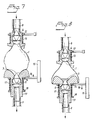
- the relative separating force between the inlet 2 and the outlet 3, which in the illustrated embodiment is generated by the weight of the outlet 3 with the outlet valve 5 and the blood in the pump chamber 1, may naturally also and equally well be generated by means of a spring member acting between the inlet 2 and the outlet 3. This may in particular be suitable if the pump is oriented in another way than in the embodiment illustrated, such as horizontally. It is, of course, also possible to balance the aforesaid gravity completely or partially with an opposing spring force, if suitable. Examples of such embodiments of the pump are illustrated in Figs. 7 to 10 and will be described further on.
- the pressure in the pump chamber 1, and thereby in the outlet tube 9 in the course of the discharge stroke for the pump chamber, may thus never exceed a value corresponding to the spring force of the spring means 13. If there is a complete blockage of the blood flow in the outlet tube 9, the inlet 2 with the inlet valve 4 will completely accompany the movement of the outlet 3 with the outlet valve 5 while being driven by the drive mechanism 15, whereby the effective pumping ceases completely without the necessity of influencing the driving of the holder 14 by means of the drive mechanism 15 and without the overpressure in the pump chamber 1 and thereby the outlet tube 9 exceeding a value corresponding to the spring force of the spring means 13 in the most compressed state thereof.
- the spring means 13 is thus suitably constructed in such a manner that its bias in the non-compressed state corresponds to the highest pressure that should normally exist in the outlet tube 9 and that its maximum spring force in the maximally compressed state corresponds to the highest overpressure in the outlet tube 9 that can be permitted. It will be understood that the spring means 13 may be constructed in such a manner as to enable both its biasing force and its maximum spring force as well as its characteristic between these two values to be varied or set depending on the use in question of the pump, for example depending on which circulatory system of a patient that the pump is to be connected to. It is to be noted that the illustrated location of the spring means 13 is only exemplary and for ease of illustration and that the same function may be obtained if the spring means are arranged otherwise, e.g. in the actual drive mechanism.
- FIGs. 7 and 8 illustrate the pump according to Figs. 5 and 6 modified by the addition of a spring means 17 acting between the holder 14 and a support 18 attached to an extended outlet portion 19 of the pump chamber.
- the support 18 is preferably a nut member threadedly engaged with the outlet portion 19 to permit the spring means to be suitably biased.
- the maximum subpressure that may be created in the pump chamber is thus determined by the spring force of the spring means 17 when the latter is in its most compressed state, i.e. when the holder 14 is in its lowest position.
- This spring force may be suitably set by adjusting the vertical position of the nut member 18.
- Figs. 9 and 10 illustrate a variation of the embodiment in Figs. 7 and 8 wherein the separating force acting upon the outlet portion of the pump chamber is totally independent of the movement of the holder 14.
- a spring means 20 is attached at its upper end to the outlet part 3 of the pump chamber 1 and at its lower end to an annular support 21 surrounding the extended outlet portion 19 and freely movable in relation thereto.
- the support 21 is in turn fixed to a nut member 22 threadedly engaged with a screw 23 rotatably mounted in a stationary bracket 24.
- the spring means 20 may be biased as desired.
- the spring means 20 as adjusted in the figures, will successively contract exerting a defined separating force between the inlet 2 and the outlet 3.
- the maximum subpressure created thereby in the pump chamber will correspond to the maximum spring force, and a desired maximum subpressure level in the pump chamber may thus be set by adjustment of the vertical position of the support 21.
- the spring means 20 may also, if desired, be adjusted to partially or completely balance the gravitational force of the outlet 3 with the outlet valve 5 and the blood quantity present in the pump chamber 1.
- the described function of the pump will also be obtained if the holder 14 for the outlet 3 with the outlet valve 5 is stationary, while the holder 12 for the inlet 2 with the inlet valve 4 is instead forcibly reciprocated by means of the drive mechanism 15.
- the same functional mode will also be obtained if the two holders 12 and 14 are movable and reciprocated by means of a common drive mechanism or individual drive mechanisms, the sum of the distances of movement of the two holders corresponding to the maximally desired relative displacement between the inlet 2 and the outlet 3 of the pump chamber 1.
- the movement distance of each holder may, for example, correspond to half the maximally desired displacement between the inlet and the outlet.
- the magnitude of the pumped flow may be varied, not only by varying the frequency and stroke length of the driving, but also by changing the relative phase position of the drivings of the two holders 12, 14, a maximum pumped flow being obtained when the holders 12, 14 move in counter-phase, while the effective pumping will be zero if the holders 12 and 14 are driven in phase with each other.
- the pump according to the invention also involves the very important advantage that when the pump is in use, for example in conjunction with a surgical procedure, the effective pumping can be stopped at any time by closing either the inlet tube 8 or the outlet tube 9 with a forceps, and then starting the pumping again by removing the forceps, without the operation of the pump by means of its drive means having to be influenced in any way and without any risk that neither unpermissible subpressures nor unpermissible overpressures may be created.
Landscapes
- Health & Medical Sciences (AREA)
- Heart & Thoracic Surgery (AREA)
- Engineering & Computer Science (AREA)
- Cardiology (AREA)
- Animal Behavior & Ethology (AREA)
- General Health & Medical Sciences (AREA)
- Anesthesiology (AREA)
- Biomedical Technology (AREA)
- Hematology (AREA)
- Life Sciences & Earth Sciences (AREA)
- Veterinary Medicine (AREA)
- Mechanical Engineering (AREA)
- Public Health (AREA)
- Pulmonology (AREA)
- Physics & Mathematics (AREA)
- Optics & Photonics (AREA)
- Emergency Medicine (AREA)
- Urology & Nephrology (AREA)
- External Artificial Organs (AREA)
- Reciprocating Pumps (AREA)
Priority Applications (1)
| Application Number | Priority Date | Filing Date | Title |
|---|---|---|---|
| AT90850307T ATE99552T1 (de) | 1989-09-15 | 1990-09-14 | Fluessigkeitspumpe mit flexibler pumpenkammer. |
Applications Claiming Priority (4)
| Application Number | Priority Date | Filing Date | Title |
|---|---|---|---|
| SE8903040A SE466989B (sv) | 1989-09-15 | 1989-09-15 | Blodpump |
| SE8903040 | 1989-09-15 | ||
| SE8903039 | 1989-09-15 | ||
| SE8903039A SE466988B (sv) | 1989-09-15 | 1989-09-15 | Blodpump |
Publications (2)
| Publication Number | Publication Date |
|---|---|
| EP0418207A1 true EP0418207A1 (de) | 1991-03-20 |
| EP0418207B1 EP0418207B1 (de) | 1994-01-05 |
Family
ID=26660592
Family Applications (1)
| Application Number | Title | Priority Date | Filing Date |
|---|---|---|---|
| EP90850307A Expired - Lifetime EP0418207B1 (de) | 1989-09-15 | 1990-09-14 | Flüssigkeitspumpe mit flexibler Pumpenkammer |
Country Status (9)
| Country | Link |
|---|---|
| US (1) | US5209654A (de) |
| EP (1) | EP0418207B1 (de) |
| JP (1) | JP2858946B2 (de) |
| CN (1) | CN1050251A (de) |
| AU (1) | AU6416990A (de) |
| DE (1) | DE69005752T2 (de) |
| IE (1) | IE903101A1 (de) |
| PT (1) | PT95320A (de) |
| WO (1) | WO1991004063A1 (de) |
Cited By (3)
| Publication number | Priority date | Publication date | Assignee | Title |
|---|---|---|---|---|
| ES2061345A1 (es) * | 1991-08-27 | 1994-12-01 | Canizo Lopez Juan Fco Del | Ventriculo artificial |
| GB2302045A (en) * | 1995-06-09 | 1997-01-08 | Calvin John Ryan | Pump for blood treatment; pressure sensor |
| RU2133128C1 (ru) * | 1997-09-25 | 1999-07-20 | Московский государственный авиационный институт | Центробежный насос для вспомогательного кровообращения |
Families Citing this family (16)
| Publication number | Priority date | Publication date | Assignee | Title |
|---|---|---|---|---|
| SE9002051L (sv) * | 1990-06-07 | 1992-01-07 | Astra Tech Ab | Ventilanordning och foertraengningspump |
| CA2278239C (en) | 1997-01-17 | 2003-12-23 | Niagara Pump Corporation | Linear peristaltic pump |
| US5964580A (en) * | 1997-04-18 | 1999-10-12 | Taga; Jun | Positive displacement pump having a ratchet drive guide for dispersing cyclic compression stresses over the circumference of an internal flexible member |
| US6464476B2 (en) * | 2000-12-22 | 2002-10-15 | Anthony C. Ross | Linear pump and method |
| JP4288957B2 (ja) * | 2003-02-24 | 2009-07-01 | 株式会社ジェイ・エム・エス | 体外循環用チューブ連結管 |
| US7445531B1 (en) | 2003-08-25 | 2008-11-04 | Ross Anthony C | System and related methods for marine transportation |
| US7351235B2 (en) * | 2005-03-22 | 2008-04-01 | Jackey Chiou | Snivel removing device |
| CN1327131C (zh) * | 2005-09-08 | 2007-07-18 | 吴长海 | 多个双腔连体囊式大流量不泄漏泵 |
| WO2009155575A1 (en) * | 2008-06-19 | 2009-12-23 | Ost Medical, Inc. | Enteral feeding pump system |
| US9233053B2 (en) | 2008-06-19 | 2016-01-12 | Alcor Scientific, Inc. | Enteral feeding pump system |
| US10406076B2 (en) | 2008-06-19 | 2019-09-10 | Alcor Scientific, Inc. | Enteral feeding pump system |
| US8241042B2 (en) * | 2009-06-15 | 2012-08-14 | Fluke Corporation | Dynamic pulse simulator |
| MX2018006490A (es) * | 2015-12-17 | 2018-08-15 | Avent Inc | Bomba de infusion con sensor de alargamiento. |
| CN108678880A (zh) * | 2018-05-22 | 2018-10-19 | 湖北赛恩斯科技股份有限公司 | 一种燃油泵 |
| KR102604074B1 (ko) * | 2021-09-02 | 2023-11-22 | 세메스 주식회사 | 펌프, 약액 공급 유닛 및 기판 처리 장치 |
| CN114668968A (zh) * | 2022-03-15 | 2022-06-28 | 郭政 | 一种通体结构的泵设备、薄膜阀及血泵 |
Citations (2)
| Publication number | Priority date | Publication date | Assignee | Title |
|---|---|---|---|---|
| US3827828A (en) * | 1972-12-26 | 1974-08-06 | M Edwards | Fluid pump control system |
| WO1987003492A1 (en) * | 1985-12-05 | 1987-06-18 | Data Promeditech I.N.C. Aktiebolag | Pump |
Family Cites Families (5)
| Publication number | Priority date | Publication date | Assignee | Title |
|---|---|---|---|---|
| US3568659A (en) * | 1968-09-24 | 1971-03-09 | James N Karnegis | Disposable percutaneous intracardiac pump and method of pumping blood |
| US4058855A (en) * | 1976-02-12 | 1977-11-22 | Runge Thomas M | Cardiac pumping device |
| DE3420861A1 (de) * | 1984-06-05 | 1985-12-05 | Biotest Pharma GmbH, 6000 Frankfurt | Schlauchpumpe fuer medizinische zwecke |
| US4781716A (en) * | 1987-02-13 | 1988-11-01 | Marc Richelsoph | Artificial heart |
| US4840205A (en) * | 1988-07-08 | 1989-06-20 | Tetra Pak Finance & Trading S.A. | Method and apparatus for dispensing liquids |
-
1990
- 1990-08-24 IE IE310190A patent/IE903101A1/en unknown
- 1990-09-14 DE DE69005752T patent/DE69005752T2/de not_active Expired - Fee Related
- 1990-09-14 EP EP90850307A patent/EP0418207B1/de not_active Expired - Lifetime
- 1990-09-14 AU AU64169/90A patent/AU6416990A/en not_active Abandoned
- 1990-09-14 US US07/834,291 patent/US5209654A/en not_active Expired - Fee Related
- 1990-09-14 PT PT95320A patent/PT95320A/pt not_active Application Discontinuation
- 1990-09-14 WO PCT/SE1990/000585 patent/WO1991004063A1/en not_active Ceased
- 1990-09-14 JP JP2513342A patent/JP2858946B2/ja not_active Expired - Fee Related
- 1990-09-15 CN CN90107819A patent/CN1050251A/zh active Pending
Patent Citations (2)
| Publication number | Priority date | Publication date | Assignee | Title |
|---|---|---|---|---|
| US3827828A (en) * | 1972-12-26 | 1974-08-06 | M Edwards | Fluid pump control system |
| WO1987003492A1 (en) * | 1985-12-05 | 1987-06-18 | Data Promeditech I.N.C. Aktiebolag | Pump |
Cited By (3)
| Publication number | Priority date | Publication date | Assignee | Title |
|---|---|---|---|---|
| ES2061345A1 (es) * | 1991-08-27 | 1994-12-01 | Canizo Lopez Juan Fco Del | Ventriculo artificial |
| GB2302045A (en) * | 1995-06-09 | 1997-01-08 | Calvin John Ryan | Pump for blood treatment; pressure sensor |
| RU2133128C1 (ru) * | 1997-09-25 | 1999-07-20 | Московский государственный авиационный институт | Центробежный насос для вспомогательного кровообращения |
Also Published As
| Publication number | Publication date |
|---|---|
| EP0418207B1 (de) | 1994-01-05 |
| US5209654A (en) | 1993-05-11 |
| PT95320A (pt) | 1991-05-22 |
| DE69005752T2 (de) | 1994-07-14 |
| DE69005752D1 (de) | 1994-02-17 |
| IE903101A1 (en) | 1991-02-27 |
| AU6416990A (en) | 1991-04-18 |
| CN1050251A (zh) | 1991-03-27 |
| JPH05500622A (ja) | 1993-02-12 |
| WO1991004063A1 (en) | 1991-04-04 |
| JP2858946B2 (ja) | 1999-02-17 |
Similar Documents
| Publication | Publication Date | Title |
|---|---|---|
| EP0418207B1 (de) | Flüssigkeitspumpe mit flexibler Pumpenkammer | |
| EP0628138B1 (de) | Selbstregelnde blutpumpe | |
| US4015590A (en) | Balloon activated blood pump | |
| EP3512578B1 (de) | Blutpumpe | |
| US4781716A (en) | Artificial heart | |
| CH617495A5 (de) | ||
| US5222880A (en) | Self-regulating blood pump | |
| CA1253048A (en) | Blood pump | |
| JPH01136664A (ja) | 拍動ポンプ装置 | |
| EP0418208A1 (de) | Flüssigkeitspumpe und damit verbundener Antrieb | |
| KR100599986B1 (ko) | 혈액 펌프 구동기 및 이를 구비하는 혈액 펌프 시스템 | |
| EP2008675A1 (de) | Blutperfusionspumpe | |
| US20040267085A1 (en) | Ventricular assist device and accessory therefor | |
| EP1197235A1 (de) | Blutpump vorrichtung für einen extrakorporalen kreislauf und zur herzunterstützung | |
| CN1011476B (zh) | 人造心脏 | |
| US20090087328A1 (en) | Pulse generating device | |
| JP7783306B2 (ja) | パルス状流体ポンプのためのポンプ弁調節アセンブリ | |
| DD297568A5 (de) | Fluidpumpe mit flexibler pumpenkammer | |
| JPH0458958A (ja) | 血液ポンプ |
Legal Events
| Date | Code | Title | Description |
|---|---|---|---|
| PUAI | Public reference made under article 153(3) epc to a published international application that has entered the european phase |
Free format text: ORIGINAL CODE: 0009012 |
|
| AK | Designated contracting states |
Kind code of ref document: A1 Designated state(s): AT BE CH DE DK ES FR GB GR IT LI LU NL SE |
|
| 17P | Request for examination filed |
Effective date: 19910831 |
|
| RAP1 | Party data changed (applicant data changed or rights of an application transferred) |
Owner name: PHARMACIA BIOSYSTEMS AB |
|
| 17Q | First examination report despatched |
Effective date: 19930316 |
|
| GRAA | (expected) grant |
Free format text: ORIGINAL CODE: 0009210 |
|
| AK | Designated contracting states |
Kind code of ref document: B1 Designated state(s): AT BE CH DE DK ES FR GB GR IT LI LU NL SE |
|
| PG25 | Lapsed in a contracting state [announced via postgrant information from national office to epo] |
Ref country code: SE Effective date: 19940105 Ref country code: NL Effective date: 19940105 Ref country code: LI Effective date: 19940105 Ref country code: GR Free format text: LAPSE BECAUSE OF FAILURE TO SUBMIT A TRANSLATION OF THE DESCRIPTION OR TO PAY THE FEE WITHIN THE PRESCRIBED TIME-LIMIT Effective date: 19940105 Ref country code: ES Free format text: THE PATENT HAS BEEN ANNULLED BY A DECISION OF A NATIONAL AUTHORITY Effective date: 19940105 Ref country code: DK Effective date: 19940105 Ref country code: CH Effective date: 19940105 Ref country code: BE Effective date: 19940105 Ref country code: AT Effective date: 19940105 |
|
| REF | Corresponds to: |
Ref document number: 99552 Country of ref document: AT Date of ref document: 19940115 Kind code of ref document: T |
|
| REF | Corresponds to: |
Ref document number: 69005752 Country of ref document: DE Date of ref document: 19940217 |
|
| ITF | It: translation for a ep patent filed | ||
| REG | Reference to a national code |
Ref country code: CH Ref legal event code: PL |
|
| ET | Fr: translation filed | ||
| NLV1 | Nl: lapsed or annulled due to failure to fulfill the requirements of art. 29p and 29m of the patents act | ||
| PG25 | Lapsed in a contracting state [announced via postgrant information from national office to epo] |
Ref country code: LU Free format text: LAPSE BECAUSE OF NON-PAYMENT OF DUE FEES Effective date: 19940930 |
|
| PLBE | No opposition filed within time limit |
Free format text: ORIGINAL CODE: 0009261 |
|
| STAA | Information on the status of an ep patent application or granted ep patent |
Free format text: STATUS: NO OPPOSITION FILED WITHIN TIME LIMIT |
|
| 26N | No opposition filed | ||
| REG | Reference to a national code |
Ref country code: GB Ref legal event code: 732E |
|
| REG | Reference to a national code |
Ref country code: FR Ref legal event code: TP |
|
| REG | Reference to a national code |
Ref country code: GB Ref legal event code: IF02 |
|
| PGFP | Annual fee paid to national office [announced via postgrant information from national office to epo] |
Ref country code: GB Payment date: 20020828 Year of fee payment: 13 Ref country code: FR Payment date: 20020828 Year of fee payment: 13 |
|
| PGFP | Annual fee paid to national office [announced via postgrant information from national office to epo] |
Ref country code: DE Payment date: 20020917 Year of fee payment: 13 |
|
| PG25 | Lapsed in a contracting state [announced via postgrant information from national office to epo] |
Ref country code: GB Free format text: LAPSE BECAUSE OF NON-PAYMENT OF DUE FEES Effective date: 20030914 |
|
| PG25 | Lapsed in a contracting state [announced via postgrant information from national office to epo] |
Ref country code: DE Free format text: LAPSE BECAUSE OF NON-PAYMENT OF DUE FEES Effective date: 20040401 |
|
| GBPC | Gb: european patent ceased through non-payment of renewal fee |
Effective date: 20030914 |
|
| PG25 | Lapsed in a contracting state [announced via postgrant information from national office to epo] |
Ref country code: FR Free format text: LAPSE BECAUSE OF NON-PAYMENT OF DUE FEES Effective date: 20040528 |
|
| REG | Reference to a national code |
Ref country code: FR Ref legal event code: ST |
|
| PG25 | Lapsed in a contracting state [announced via postgrant information from national office to epo] |
Ref country code: IT Free format text: LAPSE BECAUSE OF NON-PAYMENT OF DUE FEES Effective date: 20050914 |