EP0418420B1 - Procédé pour la fabrication d'une prothèse pour amputé fémoral - Google Patents
Procédé pour la fabrication d'une prothèse pour amputé fémoral Download PDFInfo
- Publication number
- EP0418420B1 EP0418420B1 EP89117552A EP89117552A EP0418420B1 EP 0418420 B1 EP0418420 B1 EP 0418420B1 EP 89117552 A EP89117552 A EP 89117552A EP 89117552 A EP89117552 A EP 89117552A EP 0418420 B1 EP0418420 B1 EP 0418420B1
- Authority
- EP
- European Patent Office
- Prior art keywords
- stump
- prosthesis
- process according
- value sets
- cosmetic
- Prior art date
- Legal status (The legal status is an assumption and is not a legal conclusion. Google has not performed a legal analysis and makes no representation as to the accuracy of the status listed.)
- Expired - Lifetime
Links
- 238000004519 manufacturing process Methods 0.000 title claims abstract description 26
- 238000000034 method Methods 0.000 title claims abstract description 24
- 230000008569 process Effects 0.000 title claims abstract description 14
- 239000002537 cosmetic Substances 0.000 claims abstract description 23
- 238000005259 measurement Methods 0.000 claims abstract description 12
- 210000002414 leg Anatomy 0.000 claims description 25
- 238000003801 milling Methods 0.000 claims description 12
- 210000003414 extremity Anatomy 0.000 claims description 9
- 244000309466 calf Species 0.000 claims description 8
- 210000003423 ankle Anatomy 0.000 claims description 7
- 210000003127 knee Anatomy 0.000 claims description 6
- 238000003754 machining Methods 0.000 claims description 3
- 238000000465 moulding Methods 0.000 claims description 3
- 230000006978 adaptation Effects 0.000 claims description 2
- 230000008859 change Effects 0.000 claims description 2
- 239000007787 solid Substances 0.000 claims description 2
- 210000000629 knee joint Anatomy 0.000 description 15
- 210000000689 upper leg Anatomy 0.000 description 9
- 210000000988 bone and bone Anatomy 0.000 description 7
- 238000005253 cladding Methods 0.000 description 5
- 229910000831 Steel Inorganic materials 0.000 description 3
- 210000001217 buttock Anatomy 0.000 description 3
- 230000006835 compression Effects 0.000 description 3
- 238000007906 compression Methods 0.000 description 3
- 238000002591 computed tomography Methods 0.000 description 3
- 239000010959 steel Substances 0.000 description 3
- 230000008901 benefit Effects 0.000 description 2
- 239000006260 foam Substances 0.000 description 2
- 210000002683 foot Anatomy 0.000 description 2
- 239000011505 plaster Substances 0.000 description 2
- 238000012545 processing Methods 0.000 description 2
- 230000003068 static effect Effects 0.000 description 2
- 230000007704 transition Effects 0.000 description 2
- 208000010300 Genu Varum Diseases 0.000 description 1
- 238000002266 amputation Methods 0.000 description 1
- 239000011324 bead Substances 0.000 description 1
- 238000005266 casting Methods 0.000 description 1
- 238000011960 computer-aided design Methods 0.000 description 1
- 238000010276 construction Methods 0.000 description 1
- 230000002950 deficient Effects 0.000 description 1
- 238000011161 development Methods 0.000 description 1
- 238000010586 diagram Methods 0.000 description 1
- 229910052602 gypsum Inorganic materials 0.000 description 1
- 239000010440 gypsum Substances 0.000 description 1
- 238000012986 modification Methods 0.000 description 1
- 230000004048 modification Effects 0.000 description 1
- 230000009467 reduction Effects 0.000 description 1
- 230000001105 regulatory effect Effects 0.000 description 1
- 229920002379 silicone rubber Polymers 0.000 description 1
- 239000004945 silicone rubber Substances 0.000 description 1
- 238000003860 storage Methods 0.000 description 1
- 230000009897 systematic effect Effects 0.000 description 1
- 239000013598 vector Substances 0.000 description 1
Images


Classifications
-
- A—HUMAN NECESSITIES
- A61—MEDICAL OR VETERINARY SCIENCE; HYGIENE
- A61F—FILTERS IMPLANTABLE INTO BLOOD VESSELS; PROSTHESES; DEVICES PROVIDING PATENCY TO, OR PREVENTING COLLAPSING OF, TUBULAR STRUCTURES OF THE BODY, e.g. STENTS; ORTHOPAEDIC, NURSING OR CONTRACEPTIVE DEVICES; FOMENTATION; TREATMENT OR PROTECTION OF EYES OR EARS; BANDAGES, DRESSINGS OR ABSORBENT PADS; FIRST-AID KITS
- A61F2/00—Filters implantable into blood vessels; Prostheses, i.e. artificial substitutes or replacements for parts of the body; Appliances for connecting them with the body; Devices providing patency to, or preventing collapsing of, tubular structures of the body, e.g. stents
- A61F2/50—Prostheses not implantable in the body
- A61F2/5044—Designing or manufacturing processes
- A61F2/5046—Designing or manufacturing processes for designing or making customized prostheses, e.g. using templates, finite-element analysis or CAD-CAM techniques
-
- A—HUMAN NECESSITIES
- A61—MEDICAL OR VETERINARY SCIENCE; HYGIENE
- A61F—FILTERS IMPLANTABLE INTO BLOOD VESSELS; PROSTHESES; DEVICES PROVIDING PATENCY TO, OR PREVENTING COLLAPSING OF, TUBULAR STRUCTURES OF THE BODY, e.g. STENTS; ORTHOPAEDIC, NURSING OR CONTRACEPTIVE DEVICES; FOMENTATION; TREATMENT OR PROTECTION OF EYES OR EARS; BANDAGES, DRESSINGS OR ABSORBENT PADS; FIRST-AID KITS
- A61F2/00—Filters implantable into blood vessels; Prostheses, i.e. artificial substitutes or replacements for parts of the body; Appliances for connecting them with the body; Devices providing patency to, or preventing collapsing of, tubular structures of the body, e.g. stents
- A61F2/50—Prostheses not implantable in the body
- A61F2/78—Means for protecting prostheses or for attaching them to the body, e.g. bandages, harnesses, straps, or stockings for the limb stump
- A61F2/80—Sockets, e.g. of suction type
-
- A—HUMAN NECESSITIES
- A61—MEDICAL OR VETERINARY SCIENCE; HYGIENE
- A61F—FILTERS IMPLANTABLE INTO BLOOD VESSELS; PROSTHESES; DEVICES PROVIDING PATENCY TO, OR PREVENTING COLLAPSING OF, TUBULAR STRUCTURES OF THE BODY, e.g. STENTS; ORTHOPAEDIC, NURSING OR CONTRACEPTIVE DEVICES; FOMENTATION; TREATMENT OR PROTECTION OF EYES OR EARS; BANDAGES, DRESSINGS OR ABSORBENT PADS; FIRST-AID KITS
- A61F2/00—Filters implantable into blood vessels; Prostheses, i.e. artificial substitutes or replacements for parts of the body; Appliances for connecting them with the body; Devices providing patency to, or preventing collapsing of, tubular structures of the body, e.g. stents
- A61F2/50—Prostheses not implantable in the body
- A61F2002/5001—Cosmetic coverings
-
- A—HUMAN NECESSITIES
- A61—MEDICAL OR VETERINARY SCIENCE; HYGIENE
- A61F—FILTERS IMPLANTABLE INTO BLOOD VESSELS; PROSTHESES; DEVICES PROVIDING PATENCY TO, OR PREVENTING COLLAPSING OF, TUBULAR STRUCTURES OF THE BODY, e.g. STENTS; ORTHOPAEDIC, NURSING OR CONTRACEPTIVE DEVICES; FOMENTATION; TREATMENT OR PROTECTION OF EYES OR EARS; BANDAGES, DRESSINGS OR ABSORBENT PADS; FIRST-AID KITS
- A61F2/00—Filters implantable into blood vessels; Prostheses, i.e. artificial substitutes or replacements for parts of the body; Appliances for connecting them with the body; Devices providing patency to, or preventing collapsing of, tubular structures of the body, e.g. stents
- A61F2/50—Prostheses not implantable in the body
- A61F2/5044—Designing or manufacturing processes
- A61F2/5046—Designing or manufacturing processes for designing or making customized prostheses, e.g. using templates, finite-element analysis or CAD-CAM techniques
- A61F2002/505—Designing or manufacturing processes for designing or making customized prostheses, e.g. using templates, finite-element analysis or CAD-CAM techniques using CAD-CAM techniques or NC-techniques
-
- A—HUMAN NECESSITIES
- A61—MEDICAL OR VETERINARY SCIENCE; HYGIENE
- A61F—FILTERS IMPLANTABLE INTO BLOOD VESSELS; PROSTHESES; DEVICES PROVIDING PATENCY TO, OR PREVENTING COLLAPSING OF, TUBULAR STRUCTURES OF THE BODY, e.g. STENTS; ORTHOPAEDIC, NURSING OR CONTRACEPTIVE DEVICES; FOMENTATION; TREATMENT OR PROTECTION OF EYES OR EARS; BANDAGES, DRESSINGS OR ABSORBENT PADS; FIRST-AID KITS
- A61F2/00—Filters implantable into blood vessels; Prostheses, i.e. artificial substitutes or replacements for parts of the body; Appliances for connecting them with the body; Devices providing patency to, or preventing collapsing of, tubular structures of the body, e.g. stents
- A61F2/50—Prostheses not implantable in the body
- A61F2/5044—Designing or manufacturing processes
- A61F2/5046—Designing or manufacturing processes for designing or making customized prostheses, e.g. using templates, finite-element analysis or CAD-CAM techniques
- A61F2002/5053—Designing or manufacturing processes for designing or making customized prostheses, e.g. using templates, finite-element analysis or CAD-CAM techniques using a positive or a negative model, e.g. casting model or mould
Definitions
- the invention relates to a method for producing a thigh prosthesis, in which a prosthesis socket with an articulated fitting anchored to it is formed from a positive model corresponding to the residual body part dimensions and then the prosthesis socket is covered or encased with a cosmetic covering of the prosthesis.
- Thigh prostheses in particular are manufactured using a negative model which is produced by molding the corresponding part of the patient's body and has an elongated basic shape which is open at least at one end and whose inner shape corresponds to the inner surface of the body connecting piece of the prosthesis to be produced.
- a hardening mass in particular gypsum
- gypsum is applied in a deformable state to the residual body part in a length which corresponds to the intended contact and support area of the prosthesis on the residual body part
- the negative model after hardening in an essentially dome-shaped basic shape is removed from the residual body part.
- the plaster layer is removed and serves as a negative model for the production of the body connector of the prosthesis.
- a positive model is produced by pouring out the negative model, which is used for producing the connector of the prosthesis, or the connector must be made by hand with the negative model as a template. Manufacturing by hand requires precise manual work, which involves a relatively large number of errors.
- a scanning device is displaceable on this guide device, for example rotatably mounted about the central axis of this guide device, wherein the measurement data determined by the scanning device via the profile of the negative model can be used to manufacture the prosthesis.
- this procedure requires a negative model that is produced without errors. Inaccuracies that may occur during the production of negative models are taken over during the manufacture of prostheses.
- the invention has for its object to develop the above-mentioned method for producing a thigh prosthesis in such a way that the sources of error when measuring the residual body part (positive stump) are minimized as possible, the measurement accuracy is improved overall, the respective effort of the method and the device by extensive automation should be minimized.
- the procedure according to the invention is such that the respective radial circumferential lines of at least two original archetypes for residual body stumps and / or cosmetic linings are stored disc-wise as sets of values (length x, polar coordinates y of the radius, angular dimension z) such that the circumference above the tapered portion of the residual body stump Stump and at predetermined intervals in the area of the tapered stump and / or the remaining right or left extremity (leg) as well as the respective length of the stump and / or the extremity is measured and compared with the stored value sets.
- the theoretical archetype closest to the residual body stump or the extremity is selected, the sets of values of this theoretical archetype being used to form a positive model, and the circumference above the stump is determined by adapting one of several, preferably three, form rings.
- This method has the advantage that a body stump positive model can be produced by a single measurement, which makes further patient visits for the purpose of fitting the prosthesis superfluous.
- both the scope and the so-called biomechanical shape limb thickness, leg shape
- biomechanical shape limb thickness, leg shape
- Several measurements are taken in the area of the patient's stump. Firstly, the circumference is above the tapered area the stump dome. For this, a number of shaped rings are used, from which the appropriate one is determined by applying them. Practical experience has shown that three form rings are already sufficient to reliably determine the size required for the manufacture of prostheses.
- shaped rings has the advantage that a measurement or incorrect listing of a dimension can be largely ruled out.
- the shape ring size and the other circumferential dimensions and the length already provide reliable information about which of the stored master models can be used for prosthesis manufacture.
- the biomechanical shape of the remaining extremity (leg) is of particular importance for the prosthesis lining. This biomechanical form is also taken into account by storing various original models.
- the number of data relating to the archetypes can be reduced by dividing them or their sets of values into slices.
- the spacing between the slices can be about 5 cm.
- the number of archetypes to be stored can be considerably minimized by taking a different form into account in one archetype by varying the spacing of the disks for which value sets are available, the closest theoretical being from the variations Original form for the stump or the cosmetic covering by comparison.
- the missing values, which determine the respective circumferential profile, between the disks can preferably be determined by interpolation.
- the positive models such as the stump and the cosmetic cladding
- this molded body is to consist of plastic or rigid foam plastic, which is easy to machine by milling.
- the machining of the molded body is carried out in disks according to the dimensions in the master model, the milling cutter preferably being controlled by a computer which simultaneously serves as a memory and comparator.
- Computer-aided manufacturing CAM
- This fully automatic control of a milling cutter by a control device should be used here in such a way that the computer has different shape ring sizes, e.g. I-III, and archetypes, e.g. two archetype sizes, saved in the form of value sets.
- the computer can determine the appropriate archetype by comparison in a comparator, if necessary by Stretch or compress a stored archetype.
- a comparator In front of this archetype of a buttock and / or the cosmetic cladding, all necessary values such as the circumferential line, length are available; these values are given as control impulses to a milling cutter, which removes the clamped workpiece, the molded body made of rigid foam plastic.
- FIG. 1 shows a body leg 10 in which the numerals 1 and 2 represent respective thigh bends from 0 to 5 degrees on the one hand and from 5 to 10 degrees on the other hand.
- the goal of every prosthesis production is to adapt the prosthesis to the leg length l 1 and the lower leg length l 1.
- Fig. 2 illustrates a residual thigh body part 12, which is the shape of a stump after a thigh amputation.
- This stump has an upper one a conical area of essentially the same circumference, the length and taper of which must be measured with respect to the prosthetic connector to be produced.
- the circumferential dimension in the upper, non-tapering region is first determined by means of a shaped ring. From a number of prefabricated shaped rings, the one is selected that comes closest in terms of its biomechanical shape and its inner circumference.
- the shaped ring is designed like a clasp as a non-closed ring and preferably consists of an addition-crosslinked, toxicologically harmless silicone rubber.
- the shaped ring has a height of approximately 15 cm.
- tapered area of the thigh stump 12 are taken at a distance of 5 cm circumferential dimensions 4-6, which are entered into a computer 17 together with the residual stump length l 12 and the shape ring size.
- the shaped ring can also be designed as a closed ring.
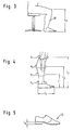
- the lower leg length l11 and the respective circumferential dimensions of the knee U1, the calf U2 and the ankle U4 of the remaining leg are also decisive.
- a further extent U3 can be measured in the transition area between calf and ankle.
- the respective length dimensions l1, l2 and l3 are to be taken from the remaining patient's leg in order to be able to adjust the prosthesis lining in the lower leg area.
- the length of the foot on the remaining patient leg l f (shoe size) determined in order to be able to manufacture the shoe 13 shown in FIG. 5.
- the desired heel height l A is also taken into account.
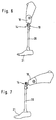
- 6 and 7 represent the entire prosthesis 14 without cladding.
- the artificial knee joint 19 has a pin for attachment to the thigh shaft 18, the pin being part of a clamping body which is pivotably attached in the knee joint 19. Furthermore, the lower leg tube 20 is connected in a rotationally secured manner to the rotatable roller body mounted in the knee joint 19 with an artificial foot 21 fastened at the end.
- a roller body is mounted in the knee joint housing in the front region of the knee joint about a horizontal axis of rotation, the end faces of the roller body having a continuous central threaded hole for screwing the roller body to the fork arms of the part which serves to receive the lower leg tube 20.
- Each of the end faces of the roller body has a parallel rib which can be inserted into a slot in each fork arm.
- the guide bead of the fork arms serves to position the fork arms in relation to the roller body which is firmly connected to them.
- a screw with the widest possible head is used for fastening.
- the knee joint has a housing with a fork-shaped receptacle for a pivot axis of the clamping body.
- the pivot axis consists of a bolt mounted in the fork-shaped receptacle, which passes through a bore in the clamping body.
- a steel part is inserted into an opening in the clamping body, wherein the steel itself has a flattened and hardened clamping surface.
- the knee joint also has a compression spring which supports the disengagement tension of the knee joint. The position of the clamping body between the roller body and the steel part can be infinitely adjusted using a set screw accommodated in the knee joint housing.
- a fastening pin for an extension is fastened horizontally in the lower area of the knee joint housing.
- both a non-rotatable roller body connected to a part for receiving the lower leg tube of a leg prosthesis and pivotally mount the clamping body in such a way that when the clamping body is subjected to a vertical load, the latter swings towards the roller body in such a way that the clamping body and the roller body come to a locking system preventing a flexion.
- Such or similar knee joint housings are known in principle from the prior art.
- Such a knee joint described above is the subject of European patent application 88112909.2, to which reference is made.
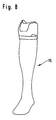
- Fig. 8 shows a cosmetic covering 15 for a lower leg prosthesis, for example for use in a prosthesis according to Figs. 6 and 7.
- This covering is in terms of its length and the biomechanical shape as well as the various circumferential dimensions in the ankle, calf and knee area remaining leg adjusted.
- FIG. 9 The method according to the invention is shown schematically in FIG. 9.
- the one that comes closest to the circumferential dimension above the tapered buttock is first selected from prefabricated shaped rings I-III.
- the shape ring 16 is determined by the scope and its biomechanical shape.
- the stump tip is measured by taking respective circumferential dimensions a, b and c at a distance of, for example, 5 cm.
- the length l12 is determined.
- the selected shape ring size, the circumferential dimensions of the die top and the length are entered into the computer 17.
- the memory of this computer can determine which form ring should be used as the basis for entering form ring I, II or III.
- the computer also contains the dimensions of at least two theoretical forms A and B, in the form of sets of values, such as triples of numbers, length x, polar coordinates y of the radius and angular dimension z. Each of these triplet numbers identifies a disc of the stump. In the present case, three disks are assumed on the original model, each lying in the area in which the circumferential dimensions a, b and c as well as the form ring I-III lie. Different dies are derived from the original shape by changing the spacing of the discs in the computer.
- the original butt shape A or B can be varied by axial compression or stretching.
- the archetypes A and B differ essentially in their biomechanical shape, for example in the narrow-wide division.
- the calculator takes on the basis of the entered values I, II or III on the one hand and a, b or c on the other hand and the length l12 the classification of the stump according to archetype A or B. in front.
- the information entered on the basis of the measurement data is processed in such a way that the computer compiles data relating to the stump tip by comparison with the possibly elongated or compressed original forms A or B.
- This data is given in the form of control pulses to a guide device 22 for a milling cutter 23, which processes a solid cylinder body 24. Control devices for milling cutters are known in the prior art.
- a positive die model is milled from the molded body 24 and is used for the production of the socket.
- the actual prosthesis socket made of plastic is obtained from the positive by deep drawing or casting.
- the cosmetic prosthesis lining is also manufactured according to the same principle.
- the length dimensions shown in Fig. 3 and 4 l11, l1, l2, l3 and l f and relevant knee, calf, ankle and intermediate area dimensions U1 to U4 are taken.
- the memory of the computer 17 as in the case of the stump dome, at least two archetypes for the cosmetic covering with their values and dimensions are stored in slices.
- the entered length and circumference dimensions of the remaining healthy patient's leg are compared in the computer with the corresponding dimensions of the archetypes stored there, if necessary after compression or extension of the archetypes.
- the data determined from this can be transmitted according to FIG.
- control impulses of a control device 22 which controls a milling cutter 23 which mills the prosthetic covering from a cylindrical full body. If the molded body is rotated, the speed of rotation of a corresponding shaft also being regulated by the computer or the control device, the milling cutter merely requires guidance in the y direction (polar coordinate) of the radius) and in the x-direction (axial direction of the stump or the cosmetic covering).
Landscapes
- Health & Medical Sciences (AREA)
- Engineering & Computer Science (AREA)
- Vascular Medicine (AREA)
- Life Sciences & Earth Sciences (AREA)
- Oral & Maxillofacial Surgery (AREA)
- Transplantation (AREA)
- Biomedical Technology (AREA)
- Heart & Thoracic Surgery (AREA)
- Manufacturing & Machinery (AREA)
- Cardiology (AREA)
- Animal Behavior & Ethology (AREA)
- General Health & Medical Sciences (AREA)
- Public Health (AREA)
- Veterinary Medicine (AREA)
- Prostheses (AREA)
- Materials For Medical Uses (AREA)
Claims (10)
- Procédé pour la fabrication d'une prothèse pour amputé fémoral dans lequel, à partir d'un modèle positif qui correspond aux dimensions du membre qui reste, une tige de prothèse est formée avec une pièce ajustée articulée, ancrée sur celle-ci, et ensuite la tige de prothèse est revêtue ou enveloppée par un habillage cosmétique,
caractérisé en ce
que les lignes circonférentielles radiales respectives d'au moins deux formes d'origine théoriques pour les moignons du membre et/ou les habillages cosmétiques sont mémorisées disque par disque comme sets de valeurs (longueur x, coordonées polaires y du rayon, mesure de l'angle z), la circonférence au-dessus du moignon qui s'effile en cône et à certains écarts prédéterminés dans la zone du moignon qui s'effile en cône et/ou de l'extrémité droite ou gauche qui reste (jambe) ainsi que la longueur respective du moignon et/ou de l'extrémité étant mesurées sur le moignon du patient et étant comparées aux sets de valeurs mémorisées, la circonférence dans la zone de même circonférence du moignon au-dessus de la zone conique de celui-ci étant déterminée par l'adaptation de l'un de plusieurs anneaux moulés, de préférence de trois anneaux moulés de type agrafe, non fermés, qui présentent une hauteur d'environ 15 cm et que la forme d'origine théorique qui s'approche le plus du moignon ou de l'extrémité étant sélectionnée et ses sets de valeurs étant utilisés pour façonner un modèle positif, la longueur de la jambe (l₁₁) ainsi que les dimensions de la circonférence du genou (U₁), du mollet (U₂), de la cheville (U₄) et d'une zone intermédiaire de la jambe située entre le mollet (U₂) et la cheville (U₄) du reste de la jambe, ainsi que leurs longueurs (l₁, l₂, l₃) de la surface de pose du pied jusqu'à la zone intermédiaire de la jambe, jusqu'au mollet et au genou étant mises en mémoire pour fabriquer l'habillage cosmétique pour la prothèse, valeurs qui sont utilisées comme impulsions de commande pour la commande entièrement automatique d'un dispositif de guidage pour une fraise qui usine un cylindre plein. - Procédé selon la revendication 1,
caractérisé en ce
que les anneaux moulés possèdent différentes formes biomécaniques. - Procédé selon l'une des revendications 1 ou 2,
caractérisé en ce
que les disques des formes d'origine, qui sont déterminés par les sets de valeurs, et/ou les écarts prédéterminés, auxquels le moignon est mesuré, sont équidistants, de préférence de 5 cm. - Procédé selon l'une des revendications 1 à 3,
caractérisé en ce
que l'habillage cosmétique est déterminé par au moins trois sets de valeurs de l'extrémité qui reste. - Procédé selon l'une des revendications 1 à 4,
caractérisé en ce
que les formes d'origine varient par la modification de l'écart entre les disques (sets de valeurs) dans la longueur et que la forme d'origine théorique la plus proche est sélectionnée parmi les variations qui résultent. - Procédé selon la revendication 5,
caractérisé en ce
que les valeurs qui manquent, qui déterminent le cours respectif de la circonférence, entre les disques sont déterminées par interpolation. - Procédé selon l'une des revendications 1 à 6,
caractérisé en ce
que les modèles positifs (moignon, habillage cosmétique) sont fabriqués par l'action d'enlever, en particulier par tournage ou fraisage d'un corps moulé. - Procédé selon la revendication 7,
caractérisé en ce
que le corps moulé est constitué en matière plastique, de préférence en mousse rigide plastique. - Procédé selon l'une des revendications 1 à 8,
caractérisé en ce
que le corps moulé est usiné disque par disque. - Procédé selon l'une des revendications 1 à 9,
caractérisé en ce
que la fraise est commandée par un ordinateur qui sert simultanément de mémoire et de comparateur.
Priority Applications (4)
| Application Number | Priority Date | Filing Date | Title |
|---|---|---|---|
| ES89117552T ES2085264T3 (es) | 1989-09-22 | 1989-09-22 | Procedimiento para confeccionar una protesis de muslo. |
| DE58909613T DE58909613D1 (de) | 1989-09-22 | 1989-09-22 | Verfahren zur Herstellung einer Oberschenkelprothese |
| AT89117552T ATE134499T1 (de) | 1989-09-22 | 1989-09-22 | Verfahren zur herstellung einer oberschenkelprothese |
| EP89117552A EP0418420B1 (fr) | 1989-09-22 | 1989-09-22 | Procédé pour la fabrication d'une prothèse pour amputé fémoral |
Applications Claiming Priority (1)
| Application Number | Priority Date | Filing Date | Title |
|---|---|---|---|
| EP89117552A EP0418420B1 (fr) | 1989-09-22 | 1989-09-22 | Procédé pour la fabrication d'une prothèse pour amputé fémoral |
Publications (2)
| Publication Number | Publication Date |
|---|---|
| EP0418420A1 EP0418420A1 (fr) | 1991-03-27 |
| EP0418420B1 true EP0418420B1 (fr) | 1996-02-28 |
Family
ID=8201916
Family Applications (1)
| Application Number | Title | Priority Date | Filing Date |
|---|---|---|---|
| EP89117552A Expired - Lifetime EP0418420B1 (fr) | 1989-09-22 | 1989-09-22 | Procédé pour la fabrication d'une prothèse pour amputé fémoral |
Country Status (4)
| Country | Link |
|---|---|
| EP (1) | EP0418420B1 (fr) |
| AT (1) | ATE134499T1 (fr) |
| DE (1) | DE58909613D1 (fr) |
| ES (1) | ES2085264T3 (fr) |
Families Citing this family (3)
| Publication number | Priority date | Publication date | Assignee | Title |
|---|---|---|---|---|
| DE4328380C1 (de) * | 1993-08-24 | 1995-04-13 | Lauth Klaus | Verfahren zur Herstellung und/oder Maßkorrektur von an Bereichen eines lebenden Körpers angepaßten Hilfsteilen und Meßvorrichtung für die Durchführung des Verfahrens |
| DE102005044974A1 (de) * | 2005-09-20 | 2007-03-22 | Heilmann & Sorge GbR (Vertretungsberechtigte Gesellschafter: Petra Heilmann und Jens Sorge, 21337 Lüneburg) | Gerät zum Einstellen von Prothesen |
| DE102014213294B4 (de) * | 2014-07-09 | 2016-10-13 | Voith Patent Gmbh | Verfahren zur Herstellung von Prothesen-Formteilen aus faserverstärktem Kunststoff |
Family Cites Families (3)
| Publication number | Priority date | Publication date | Assignee | Title |
|---|---|---|---|---|
| FR1295010A (fr) * | 1961-05-25 | 1962-06-01 | Abaque pour sélection de gaines de protection pour amputés ou de bonnet couvremoignon correspondant | |
| GB2080114B (en) * | 1980-07-16 | 1984-03-14 | Vessa Ltd | Method of making an artificial leg |
| DE3626549A1 (de) * | 1986-08-06 | 1988-02-11 | Mecron Med Prod Gmbh | Verfahren zur herstellung einer endoprothese mit individueller anpassung |
-
1989
- 1989-09-22 EP EP89117552A patent/EP0418420B1/fr not_active Expired - Lifetime
- 1989-09-22 ES ES89117552T patent/ES2085264T3/es not_active Expired - Lifetime
- 1989-09-22 AT AT89117552T patent/ATE134499T1/de not_active IP Right Cessation
- 1989-09-22 DE DE58909613T patent/DE58909613D1/de not_active Expired - Fee Related
Also Published As
| Publication number | Publication date |
|---|---|
| EP0418420A1 (fr) | 1991-03-27 |
| DE58909613D1 (de) | 1996-04-04 |
| ATE134499T1 (de) | 1996-03-15 |
| ES2085264T3 (es) | 1996-06-01 |
Similar Documents
| Publication | Publication Date | Title |
|---|---|---|
| DE69023009T2 (de) | Verfahren und anordnung zur digitalisierung durch einen laser zur herstellung von prothesen. | |
| DE69631843T2 (de) | Verfahren zur herstellung einer zahnprothese | |
| DE3203937C2 (de) | Verfahren und Vorrichtung zum maschinellen Sanieren oder Korrigieren mindestens eines Zahnes oder zum maschinellen Vorbereiten mindestens eines Zahnes für eine festsitzende prothetische Restaurierung und zum maschinellen Herstellen der festsitzenden prothetischen Restaurierung | |
| DE3712084C2 (de) | Verfahren und Einrichtung zur Herstellung einer modifizierten, dreidimensionalen Reproduktion eines weichen, deformierbaren Objektes | |
| DE3779764T2 (de) | Verfahren und vorrichtung zum herstellen einer bruecke fuer verankerungselemente im dentin. | |
| DE602005004716T2 (de) | Verfahren zur Erzeugung von dreidimensionalen Formdaten einer Zahnprothese | |
| EP0093869A1 (fr) | Prothèses articulaires formées individuellement | |
| DE20105248U1 (de) | Fräs-/Schleifmaschine zur Herstellung von zahnmedizinischen Werkstücken | |
| WO1995015131A1 (fr) | Procede de fabrication d'endoprotheses | |
| EP1062916A2 (fr) | Procédé de fabrication personnalisé de prothèses dentaires fixées sur implants et procédé de fabrication d'une prothèse dentaire, en particulier d'une quelconque matière, aussi en matière biocompatible, en particulier à l'aide de la CAD-CAM meulage et fraisage méthode | |
| DE102012009507A1 (de) | Vorrichtung und Verfahren zur Bestimmung von Fehlstellungen im Aufbau von Prothesen | |
| DE19642247C1 (de) | Verfahren zur Herstellung eines Zahnersatzteils | |
| EP3419566B1 (fr) | Méthode et dispositif pour modeler un moignon | |
| DE69123846T2 (de) | Verfahren zum bereitstellen einer prothetischen vorrichtung | |
| EP0418420B1 (fr) | Procédé pour la fabrication d'une prothèse pour amputé fémoral | |
| DE102015200627A1 (de) | Haltevorrichtung für die Herstellung einer Orthese sowie Vorrichtung und Verfahren zur Herstellung einer Orthese | |
| DE102014102997B4 (de) | Verfahren zur Statikübertragung eines orthopädischen Testhilfsmittels auf ein definitives orthopädisches Hilfsmittel | |
| DE3909655A1 (de) | Verfahren zur herstellung eines zahnersatzteils, wie krone oder bruecke, sowie artikulator und kauschablone zur durchfuehrung des verfahrens | |
| DE4232606C2 (de) | Verfahren und Vorrichtung zur Ermittlung einer dreidimensionalen Struktur der Innenoberfläche von Negativformen zur Anfertigung von Prothesen für menschliche Gliedmaßen | |
| DE10313690B4 (de) | Verarbeitung von Gestaltdaten einer Dentalprothese | |
| DE102015121180B4 (de) | Vorrichtung und Verfahren zur Halterung von Prothesenzähnen | |
| EP0796063B1 (fr) | Procede de fabrication "sur mesure" d'articles prothetiques dentaires et procede de soins dentaires au moyen desdits articles | |
| EP4108212B1 (fr) | Procédé de fabrication d'un élément de liaison | |
| EP4225224B1 (fr) | Procédé et programme informatique pour créer des données de fabrication, et procédé de fabrication d'un dispositif orthopédique | |
| WO2024200675A1 (fr) | Tige de prothèse et procédé de production d'une tige de prothèse |
Legal Events
| Date | Code | Title | Description |
|---|---|---|---|
| PUAI | Public reference made under article 153(3) epc to a published international application that has entered the european phase |
Free format text: ORIGINAL CODE: 0009012 |
|
| 17P | Request for examination filed |
Effective date: 19901220 |
|
| AK | Designated contracting states |
Kind code of ref document: A1 Designated state(s): AT BE CH DE ES FR GB IT LI LU NL SE |
|
| 17Q | First examination report despatched |
Effective date: 19921029 |
|
| ITF | It: translation for a ep patent filed | ||
| GRAA | (expected) grant |
Free format text: ORIGINAL CODE: 0009210 |
|
| AK | Designated contracting states |
Kind code of ref document: B1 Designated state(s): AT BE CH DE ES FR GB IT LI LU NL SE |
|
| REF | Corresponds to: |
Ref document number: 134499 Country of ref document: AT Date of ref document: 19960315 Kind code of ref document: T |
|
| ET | Fr: translation filed | ||
| GBT | Gb: translation of ep patent filed (gb section 77(6)(a)/1977) |
Effective date: 19960226 |
|
| REF | Corresponds to: |
Ref document number: 58909613 Country of ref document: DE Date of ref document: 19960404 |
|
| REG | Reference to a national code |
Ref country code: ES Ref legal event code: FG2A Ref document number: 2085264 Country of ref document: ES Kind code of ref document: T3 |
|
| PGFP | Annual fee paid to national office [announced via postgrant information from national office to epo] |
Ref country code: GB Payment date: 19960918 Year of fee payment: 8 |
|
| PG25 | Lapsed in a contracting state [announced via postgrant information from national office to epo] |
Ref country code: AT Effective date: 19960922 |
|
| PG25 | Lapsed in a contracting state [announced via postgrant information from national office to epo] |
Ref country code: SE Effective date: 19960923 Ref country code: ES Free format text: LAPSE BECAUSE OF THE APPLICANT RENOUNCES Effective date: 19960923 |
|
| PGFP | Annual fee paid to national office [announced via postgrant information from national office to epo] |
Ref country code: DE Payment date: 19960927 Year of fee payment: 8 |
|
| PG25 | Lapsed in a contracting state [announced via postgrant information from national office to epo] |
Ref country code: LU Free format text: LAPSE BECAUSE OF NON-PAYMENT OF DUE FEES Effective date: 19960930 Ref country code: LI Effective date: 19960930 Ref country code: CH Effective date: 19960930 Ref country code: BE Effective date: 19960930 |
|
| PGFP | Annual fee paid to national office [announced via postgrant information from national office to epo] |
Ref country code: FR Payment date: 19960930 Year of fee payment: 8 |
|
| PLBE | No opposition filed within time limit |
Free format text: ORIGINAL CODE: 0009261 |
|
| STAA | Information on the status of an ep patent application or granted ep patent |
Free format text: STATUS: NO OPPOSITION FILED WITHIN TIME LIMIT |
|
| 26N | No opposition filed | ||
| BERE | Be: lapsed |
Owner name: IPOS G.M.B.H. & CO. K.G. Effective date: 19960930 |
|
| PG25 | Lapsed in a contracting state [announced via postgrant information from national office to epo] |
Ref country code: NL Effective date: 19970401 |
|
| REG | Reference to a national code |
Ref country code: CH Ref legal event code: PL |
|
| NLV4 | Nl: lapsed or anulled due to non-payment of the annual fee |
Effective date: 19970401 |
|
| EUG | Se: european patent has lapsed |
Ref document number: 89117552.3 |
|
| PG25 | Lapsed in a contracting state [announced via postgrant information from national office to epo] |
Ref country code: GB Free format text: LAPSE BECAUSE OF NON-PAYMENT OF DUE FEES Effective date: 19970922 |
|
| PG25 | Lapsed in a contracting state [announced via postgrant information from national office to epo] |
Ref country code: FR Free format text: THE PATENT HAS BEEN ANNULLED BY A DECISION OF A NATIONAL AUTHORITY Effective date: 19970930 |
|
| GBPC | Gb: european patent ceased through non-payment of renewal fee |
Effective date: 19970922 |
|
| PG25 | Lapsed in a contracting state [announced via postgrant information from national office to epo] |
Ref country code: DE Free format text: LAPSE BECAUSE OF NON-PAYMENT OF DUE FEES Effective date: 19980603 |
|
| REG | Reference to a national code |
Ref country code: FR Ref legal event code: ST |
|
| REG | Reference to a national code |
Ref country code: ES Ref legal event code: FD2A Effective date: 19991007 |
|
| PG25 | Lapsed in a contracting state [announced via postgrant information from national office to epo] |
Ref country code: IT Free format text: LAPSE BECAUSE OF NON-PAYMENT OF DUE FEES;WARNING: LAPSES OF ITALIAN PATENTS WITH EFFECTIVE DATE BEFORE 2007 MAY HAVE OCCURRED AT ANY TIME BEFORE 2007. THE CORRECT EFFECTIVE DATE MAY BE DIFFERENT FROM THE ONE RECORDED. Effective date: 20050922 |