EP0418459A2 - Appareil d'exposition - Google Patents
Appareil d'exposition Download PDFInfo
- Publication number
- EP0418459A2 EP0418459A2 EP90106335A EP90106335A EP0418459A2 EP 0418459 A2 EP0418459 A2 EP 0418459A2 EP 90106335 A EP90106335 A EP 90106335A EP 90106335 A EP90106335 A EP 90106335A EP 0418459 A2 EP0418459 A2 EP 0418459A2
- Authority
- EP
- European Patent Office
- Prior art keywords
- light source
- frame
- overhead
- exposure unit
- base
- Prior art date
- Legal status (The legal status is an assumption and is not a legal conclusion. Google has not performed a legal analysis and makes no representation as to the accuracy of the status listed.)
- Withdrawn
Links
Images




Classifications
-
- G—PHYSICS
- G03—PHOTOGRAPHY; CINEMATOGRAPHY; ANALOGOUS TECHNIQUES USING WAVES OTHER THAN OPTICAL WAVES; ELECTROGRAPHY; HOLOGRAPHY
- G03B—APPARATUS OR ARRANGEMENTS FOR TAKING PHOTOGRAPHS OR FOR PROJECTING OR VIEWING THEM; APPARATUS OR ARRANGEMENTS EMPLOYING ANALOGOUS TECHNIQUES USING WAVES OTHER THAN OPTICAL WAVES; ACCESSORIES THEREFOR
- G03B21/00—Projectors or projection-type viewers; Accessories therefor
- G03B21/134—Projectors combined with typing apparatus or with printing apparatus
-
- G—PHYSICS
- G03—PHOTOGRAPHY; CINEMATOGRAPHY; ANALOGOUS TECHNIQUES USING WAVES OTHER THAN OPTICAL WAVES; ELECTROGRAPHY; HOLOGRAPHY
- G03B—APPARATUS OR ARRANGEMENTS FOR TAKING PHOTOGRAPHS OR FOR PROJECTING OR VIEWING THEM; APPARATUS OR ARRANGEMENTS EMPLOYING ANALOGOUS TECHNIQUES USING WAVES OTHER THAN OPTICAL WAVES; ACCESSORIES THEREFOR
- G03B27/00—Photographic printing apparatus
- G03B27/02—Exposure apparatus for contact printing
- G03B27/14—Details
- G03B27/18—Maintaining or producing contact pressure between original and light-sensitive material
- G03B27/20—Maintaining or producing contact pressure between original and light-sensitive material by using a vacuum or fluid pressure
-
- G—PHYSICS
- G03—PHOTOGRAPHY; CINEMATOGRAPHY; ANALOGOUS TECHNIQUES USING WAVES OTHER THAN OPTICAL WAVES; ELECTROGRAPHY; HOLOGRAPHY
- G03B—APPARATUS OR ARRANGEMENTS FOR TAKING PHOTOGRAPHS OR FOR PROJECTING OR VIEWING THEM; APPARATUS OR ARRANGEMENTS EMPLOYING ANALOGOUS TECHNIQUES USING WAVES OTHER THAN OPTICAL WAVES; ACCESSORIES THEREFOR
- G03B27/00—Photographic printing apparatus
- G03B27/02—Exposure apparatus for contact printing
- G03B27/14—Details
- G03B27/16—Illumination arrangements, e.g. positioning of lamps, positioning of reflectors
Definitions
- the present invention relates to overhead exposure units for reproducing film images on photosensitive sheets such as silk screen, films, printing plates and the like used in the graphic arts industry.
- the present invention is directed towards a new and improved light exposure unit in which a light source is positioned with a relatively short distance between the light source and a silk screen, film or sheet on which an image is being reproduced so that a relatively high light intensity is afforded thereby minimizing the exposure time interval required during an operating exposure cycle.
- a unique overhead exposure unit wherein a light source, a glass panel and a supporting panel frame are pivotally movable relative to a horizontal base and vacuum blanket between a first or exposure position and a second or open position for providing easy loading and unloading of the film, silk screen, sheets etc.
- Another object of the present invention is to provide a new and improved overhead exposure unit of the character described wherein an overhead light source and housing therefor is not maintained in a fixed relationship to a vacuum frame, but instead is movable so as to provide for better viewing during loading and unloading operations while minimizing the light source to vacuum frame exposure distance so that the time duration or interval of light exposure is maintained at a minimum.
- Yet another object of the present invention is to provide a new and improved overhead light exposure unit of the type which employs a light source and supporting housing therefor that is movable yet remains at all times within a confined space above a fixed vacuum frame within a perimeter thereof.
- Yet another object of the present invention is to provide a new and improved overhead light exposure unit of the character described which provides for better viewing of the vacuum frame during loading and unloading operations yet still provides a minimum spacing between the light source and the frame during a light exposure period of an operating reproduction cycle.
- the foregoing and other objects and advantages of the present invention are accomplished in a new and improved overhead light exposure unit for making film image reproductions on photosensitive sheets such as silk screens, media sheets, plates, films and the like.
- the exposure unit includes a base having a horizontally disposed vacuum blanket for pressing sheets and image forming films together against a transparent panel of glass or plastic.
- a frame supporting the transparent panel is pivotally mounted on the base for movement between an exposure position, generally horizontally parallel to and closely adjacent the vacuum blanket and an open position sloping upwardly thereof for providing ample open work space for convenience in the unloading and loading of sheet materials between exposures.
- the light source is positioned above the base for housing and directing a controlled intensity light beam downwardly through the transparent panel for reproducing images on one or more sheets held in precise registration with an image sheet by the horizontally disposed vacuum blanket.
- a support system is provided for holding the light source in an exposure position directly above the panel at a minimum light source to film distance and yet permitting movement of the light source in response to movement of the frame from a horizontal closed position toward an open position wherein interference to viewing of and access to the work area above the vacuum blanket is minimized during loading and unloading operations.
- FIG. 1 a side elevational view of a typical prior art overhead exposure unit 10 including a rectangular base 12 having a horizontally disposed upper work surface with a vacuum blanket 14 mounted thereon.
- a frame 16 is pivotally connected to the base 12 along a rearward edge and a pair of air springs 18 are provided on opposite sides to support the frame 16 in an upwardly sloping or tilted open position as shown.
- the prior art exposure unit includes a lamp housing 20 supported at a fixed or constant level above the horizontal vacuum blanket 14 on a pair of upstanding side supports 22.
- the lamp housing 20 contains a high intensity lamp 24 and a reflector 26 for directing a controlled, high intensity light beam indicated by the ray lines 28 downwardly through a glass panel contained in the frame 16 to reproduce images on film sheets, silk screens, plates, and the like, which are together in contact with a master image film sheet pressed against the glass panel of the frame 16.
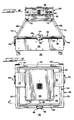
- FIGS. 2-5 therein is illustrativelyed a new and improved overhead exposure unit 30 constructed in accordance with the teachings of the present invention and adapted to be supported from the floor or other support structure so that the upper, horizontal working surface of a rectangular base 32 is maintained at a convenient working level for an operator 34 standing in front of the unit and looking forwardly and downwardly at an angle towards an upper work surface of the base.
- the base 32 provides support for a vacuum blanket assembly 36, which may be of a fast draw-down type as shown and described in copening United States patent application Serial No. 353,055, filed May 17, 1989, assigned to the same assignee as the present application and incorporated hereby by reference, or a silk screen type vacuum blanket as illustrated in FIGS. 6 and 6A.
- the base 32 also provides support for a rectangular frame 38 which carries a flat, rectangular-shaped, transparent panel 40 of glass or plastic as best shown in FIGS. 6 and 6A.
- the frame 38 is pivotally secured to a rear side member of the base 32 with a plurality of hinges 42 for pivotal movement between a closed, horizontally disposed, exposure position as shown in FIGS. 2, 3, 4 and 5 and an upwardly sloping open position as shown in FIG. 3A.
- the frame 38 may be of a type shown and described in a copending United States patent application Serial No. 369,334, filed June 21, 1989, assigned to the same assignee as the present application and incorporated herein by reference.
- the frame 38 includes a latching mechanism 44 mounted on a front side member 48 of the frame adapted to latchingly engage a strike mechanism 46 mounted on a front side of the base 32 adjacent the upper edge as best shown in FIG. 3A.
- the frame 38 also includes a pair of relatively strong, stiff, metal side frame members 50 joined at their rearward ends to a rear frame member 52 carrying the upper leaves of the hinges 42.
- the respective frame members 48, 50 and 52 of the frame 38 may be formed of metal having a channel-shaped cross-section or a hollow tubular cross-section as needed to provide the desired degree of rigidity or stiffness and strength.
- the overhead exposure unit 30 is provided with a pair of air springs 54, pivotally attached at lower ends to side members of the base 32 and pivotally interconnected at their upper ends to side frame members 50 of the frame 38 as best shown in FIGS. 6 and 6A.
- the air springs 54 are chosen to have a size and strength sufficient to support the frame 38 and the components carried thereby when the frame is unlatched and tilted upwardly into the open position as shown in FIG. 3A.
- the overhead exposure unit 30 includes a generally rectangular lamp housing 56 having a control panel 58 on a front face in easy view of a standing operator 34 at approximately eye level as shown in FIG. 2.
- the lamp housing 56 contains a light source in the form of a high intensity lamp 60 which is directly centered above the frame 38 and base 32 as shown in FIG. 2.
- Light from the energized lamp 60 is fo cused and directed downwardly by an internal reflector 62 also contained in the housing 56 in order to provide a controlled light beam of proper intensity and spread angle.
- the beam indicated by ray lines 64 from the lamp 60 has a desired degree intensity when it reaches the level of the glass panel 40 in the closed horizontal position as shown in FIGS. 3 and 4.
- the lamp reflector 62 is designed so that the rays of light from the energized lamp 60 are properly focused to insure a desired level of light intensity at the horizontally disposed working surface of the glass panel of the frame 38 in a closed position.
- the same degree of light intensity at the level of the frame 38 can be obtained for frames of increased size by reducing the light source to frame exposure distance.
- a reduction in distance between the lamp source and work surface to accommodate wider and larger frames would present an obstruction to a clear view of the working area because of the position of the relatively large lamp housing in the operator's line of sight.
- the exposure distance from the lamp 60 to the vacuum blanket 36 may be reduced considerably from that of prior art units and without substantial obstruction to the view or access to the working area because of a unique feature wherein the lamp housing 56 is supported from and moves with the pivotally movable frame 38 so as to pivot upwardly out of the view of an operator 34 to an open position as shown in FIG. 3A wherein the operator's eyes at normal eye level have a nearly unobstructed view of the entire work surface of the base 32 as indicated by the ray lines 68. This result is obtained because the lamp housing 56 is tilted back and out of the way as illustrated in FIG. 3A.
- the lamp housing 56 is supported on a pair of side frame support members 70, which members in turn are fixedly attached to the side frame members of the frame 38 at their lower ends. Upper ends of the support members 70 are fixedly attached to opposite ends of the lamp housing 56 through side support angles 72 of a lower support frame of the lamp housing. It will thus be seen that the lamp 60 and its supporting housing 56 both are pivotally moved along with the frame 38 when the frame is unlatched and pivoted upwardly from the horizontally disposed exposure position as shown in FIGS. 2, 3, 4 and 5. When the frame 38 is tilted upwardly to the open position, as shown in FIG.
- the operator 34 can clearly view even a rearward portion of the work area on the vacuum blanket 36 as indicated by the ray lines 68, which lines pass through the glass panel 40.
- the lamp to vacuum frame exposure distance can be shortened up as needed to provide the same or increased intensity of light for larger and wider size frames and thus maintain or even reduce the exposure time required.
- the center of gravity of the lamp housing 56 and contents is substantially at the geometric center thereof as viewed in side elevation and even though the lamp housing 56 is pivoted or tilted upwardly and backwardly out of the way, the center of gravity thereof never moves outside of an area bounded by an upward extension of the peripheral edges of the base 32.
- This provides for a physically stable arrangement even when the lamp housing 56 and contents are relatively heavy in relation to the base 32.
- the frame 38 is unlatched and opened to pivot upwardly the lamp housing 56 and contents also tilts upwardly and backwardly out of the way to afford an excellent view of the horizontally extending working area above the base 32.
- This area is also easily accessible from the front side of the overhead exposure unit 30 between the front edge 48 of the upwardly tilted frame 38 and the horizontal work surface of the vacuum blanket 36.
- the overhead exposure unit 30 is especially well adapted for reproducing images from a master film or sheet 74 onto photo-sensitive silk screen 76 or other types of sheet media which are sometimes mounted on a relatively large wood frame 78.
- the upper portion of the base 32 is provided with a shallow, pan-like recessed top wall 80 having a solid segment around its periphery or marginal edge 32a of the base.
- the shallow recess in the central portion of the top pan 80 is adapted to accommodate a relatively thick silk screen frame 78 and the vacuum blanket assembly 36.
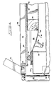
- the blanket assembly 36 includes a flexible resilient blanket 82 having a seal bead 84 around the periphery thereof adapted to provide a peripheral edge seal against the underside of the glass panel 40, whenever a space 86 (FIG. 6) between the upper surface of the flexible blanket 82 and the lower face of the glass panel 40 within the sealed periphery 84 is evacuated.
- the flexible vacuum blanket 82 when evacuation takes place, the flexible vacuum blanket 82 closely conforms to the shape of the frame 78 and biases the silk screen sheet 76 and the image forming film sheet 74 tightly against the underside of the glass panel in precise registration ready for a timed exposure cycle when the lamp 60 is illuminated.
- a vacuum is drawn on the space 86 by a vacuum pump (not shown) and a vacuum line 88 is connected from the pump to the space 86 through a bell-like fitting 90 as shown.
- the space 86 is again vented to the atmosphere and the flexible vacuum blanket 82 returns to a relaxed position as shown in FIG. 6.
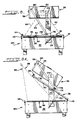
- the overhead exposure unit 130 includes a lamp housing 56 spaced above a rectangular base 32 supported on a pair of upstanding support members 170.
- the lamp housing 56 is pivotally mounted on pins 172 at the upper end of the supports 170 for pivotal movement between a horizontal, closed or exposure position as shown in FIG. 8 and an open position as shown in FIG.
- FIG. 8A wherein the lamp housing 56 is pivoted upwardly and backwardly away to afford a standing operator 34 a substantially unobstructed view of the entire horizontal work surface above the base 32 and vacuum blanket 36 as indicated by the sight or ray lines 66 in FIG. 7 and light ray lines 68 in FIG. 8A.
- a frame 38 is pivotally secured to the backside of the base 32 by a plurality of hinges 42 and when the frame 38 is unlatched and pivoted upwardly from the horizontal or exposure position of FIG. 8 to the upwardly tilted, open position of FIG. 8A, the lamp housing 56 is simultaneously pivoted to tilt upwardly and backwardly out of the way.
- a pair of pivot links 174 are interconnected between brackets 176 and pivot pins 178 attached to side members 50 of the frame 38 and pivot pins 180 attached to the lamp housing 56 on opposite sides thereof. As illustrated, when the lamp housing 56 and the frame 38 are pivoted upwardly to the open position of FIG. 8A, the interconnecting links 174 cause these two members to pivot in unison.
- the center of gravity of the lamp housing 56 is near the geometrical center thereof and moves only slightly to the rear as the housing is pivoted from the exposure position of FIG. 8 to the open position of FIG. 8A. Moreover, the entire lamp housing 56 is maintained well within a space directly above the base 32 bounded by the periphery thereof.
- the unit 130 is thus very stable in a physical sense as the frame 38 and lamp housing 56 are pivotally moved between open and closed positions during copy making and platemaking activities.
- the overhead exposure unit 130 affords the advantage of fast exposure times with large size sheets because of the relatively close spacing between the lamp 60 and the frame 38 as previously discussed herein in connection with the overhead exposure unit 30.
- both the overhead exposure unit 30 and the overhead exposure unit 130 provide for precise control and positioning of the lamp housing 56 and the lamp 60 and reflector 62 when the housing is centered above the vacuum blanket 36 in an exposure position.
- the center of the lamp 60 is positioned substantially directly above the center of the frame 38 and a center line light ray of high intensity illumination is directed vertically downwardly from the lamp 60 to strike at a right angle to the face of the closed glass panel 40 and the film sheets 74 and 76.
Landscapes
- Physics & Mathematics (AREA)
- General Physics & Mathematics (AREA)
- Fluid Mechanics (AREA)
- Exposure And Positioning Against Photoresist Photosensitive Materials (AREA)
Applications Claiming Priority (2)
| Application Number | Priority Date | Filing Date | Title |
|---|---|---|---|
| US07/407,808 US4994857A (en) | 1989-09-19 | 1989-09-19 | Overhead light exposure apparatus |
| US407808 | 1989-09-19 |
Publications (2)
| Publication Number | Publication Date |
|---|---|
| EP0418459A2 true EP0418459A2 (fr) | 1991-03-27 |
| EP0418459A3 EP0418459A3 (en) | 1992-03-11 |
Family
ID=23613599
Family Applications (1)
| Application Number | Title | Priority Date | Filing Date |
|---|---|---|---|
| EP19900106335 Withdrawn EP0418459A3 (en) | 1989-09-19 | 1990-04-03 | Overhead light exposure apparatus |
Country Status (5)
| Country | Link |
|---|---|
| US (1) | US4994857A (fr) |
| EP (1) | EP0418459A3 (fr) |
| JP (1) | JPH03144570A (fr) |
| KR (1) | KR910006769A (fr) |
| AU (1) | AU5233090A (fr) |
Cited By (1)
| Publication number | Priority date | Publication date | Assignee | Title |
|---|---|---|---|---|
| EP0702262A1 (fr) * | 1994-09-13 | 1996-03-20 | Douthitt Corporation | Appareil autonome pour exposer et développer un film |
Families Citing this family (1)
| Publication number | Priority date | Publication date | Assignee | Title |
|---|---|---|---|---|
| AU682145B3 (en) * | 1997-03-19 | 1997-09-18 | Umax Data Systems Inc. | Transparency optical scanner |
Family Cites Families (5)
| Publication number | Priority date | Publication date | Assignee | Title |
|---|---|---|---|---|
| US2366722A (en) * | 1941-07-29 | 1945-01-09 | Arthur H Gaebel | Photographic apparatus |
| US3176601A (en) * | 1962-12-03 | 1965-04-06 | James W Bradley | Step-and-repeat machine |
| US3604801A (en) * | 1968-06-11 | 1971-09-14 | Superior Electric Co | Film exposing machine for making negatives |
| GB1547971A (en) * | 1975-10-10 | 1979-07-04 | Spence Bate | Record copying support |
| US4464047A (en) * | 1983-03-16 | 1984-08-07 | Douthitt Corporation | Overhead multiple lamp mount console for a vacuum printer |
-
1989
- 1989-09-19 US US07/407,808 patent/US4994857A/en not_active Expired - Fee Related
-
1990
- 1990-03-28 AU AU52330/90A patent/AU5233090A/en not_active Abandoned
- 1990-04-03 EP EP19900106335 patent/EP0418459A3/en not_active Withdrawn
- 1990-04-16 KR KR1019900005224A patent/KR910006769A/ko not_active Withdrawn
- 1990-09-19 JP JP2249926A patent/JPH03144570A/ja active Pending
Cited By (1)
| Publication number | Priority date | Publication date | Assignee | Title |
|---|---|---|---|---|
| EP0702262A1 (fr) * | 1994-09-13 | 1996-03-20 | Douthitt Corporation | Appareil autonome pour exposer et développer un film |
Also Published As
| Publication number | Publication date |
|---|---|
| US4994857A (en) | 1991-02-19 |
| AU5233090A (en) | 1991-03-28 |
| EP0418459A3 (en) | 1992-03-11 |
| JPH03144570A (ja) | 1991-06-19 |
| KR910006769A (ko) | 1991-04-30 |
Similar Documents
| Publication | Publication Date | Title |
|---|---|---|
| EP1163881B8 (fr) | Dispositif de support d'une cassette radiographique | |
| EP0702875A1 (fr) | Procede et appareil pour archiver sous une forme numerique des images analogiques | |
| EP0418459A2 (fr) | Appareil d'exposition | |
| US3588244A (en) | Book copier attachment for a photocopy machine | |
| US4536085A (en) | Multiple vacuum frame unit | |
| US4150896A (en) | Copying apparatus cover | |
| GB1580771A (en) | Device for iluuminating an object during electrostatic reproduction thereof | |
| US5016045A (en) | Image reading apparatus | |
| US5223870A (en) | Overhead projector with image direction adjusting device | |
| US4241993A (en) | Mount for originals in photographic devices | |
| US4486094A (en) | Original holder for a printing plate processing apparatus | |
| US5117257A (en) | Contact printer | |
| JPH0990852A (ja) | 画像形成装置の外装カバー取付装置 | |
| JPH0442838Y2 (fr) | ||
| GB2062882A (en) | Contact printer | |
| USRE30878E (en) | Copying apparatus cover | |
| JP2512068Y2 (ja) | 製版カメラの撮影架 | |
| JP2593770Y2 (ja) | 透過形投影装置用アタッチメント | |
| JP2512069Y2 (ja) | 立型製版カメラの遮光ロ―ラ装置 | |
| WO1991016662A1 (fr) | Appareil photographique/projecteur a copier en repetition | |
| JPS5829455Y2 (ja) | オ−バヘツドタイププロジエクタ−の被写体押え装置 | |
| JP2728893B2 (ja) | 透過原稿投影装置 | |
| JPH0731241Y2 (ja) | 立型製版カメラの反射照明支持装置 | |
| US3932037A (en) | Original holder plate for copying machine | |
| JPH0112267Y2 (fr) |
Legal Events
| Date | Code | Title | Description |
|---|---|---|---|
| PUAI | Public reference made under article 153(3) epc to a published international application that has entered the european phase |
Free format text: ORIGINAL CODE: 0009012 |
|
| AK | Designated contracting states |
Kind code of ref document: A2 Designated state(s): BE CH DE DK ES FR GB IT LI NL SE |
|
| PUAL | Search report despatched |
Free format text: ORIGINAL CODE: 0009013 |
|
| AK | Designated contracting states |
Kind code of ref document: A3 Designated state(s): BE CH DE DK ES FR GB IT LI NL SE |
|
| STAA | Information on the status of an ep patent application or granted ep patent |
Free format text: STATUS: THE APPLICATION IS DEEMED TO BE WITHDRAWN |
|
| 18D | Application deemed to be withdrawn |
Effective date: 19920505 |