EP0418535A2 - Fokussierte Lichtquelle und Verfahren dazu - Google Patents
Fokussierte Lichtquelle und Verfahren dazu Download PDFInfo
- Publication number
- EP0418535A2 EP0418535A2 EP90115240A EP90115240A EP0418535A2 EP 0418535 A2 EP0418535 A2 EP 0418535A2 EP 90115240 A EP90115240 A EP 90115240A EP 90115240 A EP90115240 A EP 90115240A EP 0418535 A2 EP0418535 A2 EP 0418535A2
- Authority
- EP
- European Patent Office
- Prior art keywords
- source
- radiation
- reflector
- axis
- electrodes
- Prior art date
- Legal status (The legal status is an assumption and is not a legal conclusion. Google has not performed a legal analysis and makes no representation as to the accuracy of the status listed.)
- Withdrawn
Links
Images




Classifications
-
- F—MECHANICAL ENGINEERING; LIGHTING; HEATING; WEAPONS; BLASTING
- F21—LIGHTING
- F21V—FUNCTIONAL FEATURES OR DETAILS OF LIGHTING DEVICES OR SYSTEMS THEREOF; STRUCTURAL COMBINATIONS OF LIGHTING DEVICES WITH OTHER ARTICLES, NOT OTHERWISE PROVIDED FOR
- F21V29/00—Protecting lighting devices from thermal damage; Cooling or heating arrangements specially adapted for lighting devices or systems
- F21V29/50—Cooling arrangements
- F21V29/502—Cooling arrangements characterised by the adaptation for cooling of specific components
- F21V29/505—Cooling arrangements characterised by the adaptation for cooling of specific components of reflectors
-
- G—PHYSICS
- G02—OPTICS
- G02B—OPTICAL ELEMENTS, SYSTEMS OR APPARATUS
- G02B6/00—Light guides; Structural details of arrangements comprising light guides and other optical elements, e.g. couplings
- G02B6/0001—Light guides; Structural details of arrangements comprising light guides and other optical elements, e.g. couplings specially adapted for lighting devices or systems
-
- G—PHYSICS
- G02—OPTICS
- G02B—OPTICAL ELEMENTS, SYSTEMS OR APPARATUS
- G02B6/00—Light guides; Structural details of arrangements comprising light guides and other optical elements, e.g. couplings
- G02B6/0001—Light guides; Structural details of arrangements comprising light guides and other optical elements, e.g. couplings specially adapted for lighting devices or systems
- G02B6/0005—Light guides; Structural details of arrangements comprising light guides and other optical elements, e.g. couplings specially adapted for lighting devices or systems the light guides being of the fibre type
- G02B6/0006—Coupling light into the fibre
-
- F—MECHANICAL ENGINEERING; LIGHTING; HEATING; WEAPONS; BLASTING
- F21—LIGHTING
- F21S—NON-PORTABLE LIGHTING DEVICES; SYSTEMS THEREOF; VEHICLE LIGHTING DEVICES SPECIALLY ADAPTED FOR VEHICLE EXTERIORS
- F21S2/00—Systems of lighting devices, not provided for in main groups F21S4/00 - F21S10/00 or F21S19/00, e.g. of modular construction
-
- G—PHYSICS
- G02—OPTICS
- G02B—OPTICAL ELEMENTS, SYSTEMS OR APPARATUS
- G02B6/00—Light guides; Structural details of arrangements comprising light guides and other optical elements, e.g. couplings
- G02B6/24—Coupling light guides
- G02B6/42—Coupling light guides with opto-electronic elements
- G02B6/4298—Coupling light guides with opto-electronic elements coupling with non-coherent light sources and/or radiation detectors, e.g. lamps, incandescent bulbs, scintillation chambers
-
- G—PHYSICS
- G03—PHOTOGRAPHY; CINEMATOGRAPHY; ANALOGOUS TECHNIQUES USING WAVES OTHER THAN OPTICAL WAVES; ELECTROGRAPHY; HOLOGRAPHY
- G03B—APPARATUS OR ARRANGEMENTS FOR TAKING PHOTOGRAPHS OR FOR PROJECTING OR VIEWING THEM; APPARATUS OR ARRANGEMENTS EMPLOYING ANALOGOUS TECHNIQUES USING WAVES OTHER THAN OPTICAL WAVES; ACCESSORIES THEREFOR
- G03B21/00—Projectors or projection-type viewers; Accessories therefor
- G03B21/14—Details
- G03B21/20—Lamp housings
- G03B21/2006—Lamp housings characterised by the light source
- G03B21/2026—Gas discharge type light sources, e.g. arcs
Definitions
- This invention relates to light sources particularly suitable for illuminating optical fibers, and more particularly to an assembly including arc-discharge lamp and reflector which efficiently transfers visible radiation and inhibits ultraviolet and infrared radiation between light source and fibers.
- Numerous fiber-optic illumination applications require a light source that is capable of launching light flux into an optical fiber to propagate along the length of the fiber in low-order modes for long distance propagation, or in higher-order modes, for example, for lateral emission through the side surface of the fiber.
- Applications of the former type commonly use glass optical fibers, and applications of the latter type commonly use plastic optical fibers.
- plastic optical fibers care must be taken to minimize heat and ultraviolet radiation along with visible illumination because of the deleterious effect on plastic fiber materials of radiation at both ends of the spectrum around the visible spectrum.
- a light source for illuminating optical fibers ideally should supply all of the visible output flux to a focal point at which the end of an optical fiber is positioned for maximally efficient transfer of light flux into the optical fiber.
- an improved light source structure and method of optimizing the transfer of visible light flux to optical fibers includes a high-intensity, gas-discharge lamp positioned within an ellipsoidal reflector with wave length-selective coatings for enhancing the transfer of visible light flux to a focal point, or small focal area, and to minimize the heat and ultraviolet flux supplied thereto from the lamp.
- gas-discharge lamp positioned within an ellipsoidal reflector with wave length-selective coatings for enhancing the transfer of visible light flux to a focal point, or small focal area, and to minimize the heat and ultraviolet flux supplied thereto from the lamp.
- FIG. 1 there is shown a plan view of a gas-discharge lamp that includes a bulb 13 including a pair of electrode 9, 11 oriented in facing, mating alignment along an axis 14.
- the bulb 13 contains an ionizable gas (or gases) and the vapors of such metals as tin, thallium and mercury.
- Bulb 13 is formed of glass in a glass blank 15 that rigidly supports the electrodes 9, 11 and the lead-in conductors therefor 17, 19 in fixed location.
- the bulb 13 and blank 15 and lead-in conductors 17, 19 are housed within glass shell 21 that is attached to base 23 through which the lead-in conductors 17, 19 pass to form connector pins 25; 27.
- Lamps of this type are commercially available (for example, from OSRAM Corp. of Newburgh, New York), and are typically capable of emitting approximately 12000 lumens at a color temperature of about 3000°K with about 150 watts dissipation.
- the lamp illustrated in Figure 1 is illustrated in simplified end view in Figure 2.
- the electrodes 9, 11 are aligned along axis 14 and are shown spaced about a vertical axis 29 that is normal to the (horizontal) axis 14 of alignment of the electrodes, with a reflector 24 substantially axially and symmetrically disposed about the lamp.
- the lamp is illustrated symmetrically oriented about the origin of the X (horizontal) and Y (vertical) axes 14, 29 for purposes of correlating the illumination intensity distribution data of the lamp, as illustrated in the graphs of Figures 6 and 7, later described herein.
- the reflector housing 31 includes a reflector section 33, an alignment section 35, and a mounting section 37.
- the alignment section 35 is formed with internal dimensions to receive the shell 21 of the lamp in close axial alignment
- the mounting section 37 is formed with internal dimensions to receive the base 23 for attaching the components together, in the manner as later described herein, with the electrode axis located at the focal point 40 of the reflector section 33.
- the reflector section 33 is designed to focus the light that is emitted from the 'filament' of a gas-discharge arc which is maintained between electrodes 9, 11 (by conventional external circuitry that forms no part of the present invention) upon a point (or small focal area) 39 at which the end(s) of one or more optical fibers are to be located.
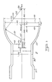
- the reflector section 33 is formed generally as a truncated, regular ellipsoidal shape of revolution about the origin axis 41, on which lay the foci 39 and 40 of the ellipsoidal shape.
- the truncations of the ellipsoid are in the plane 43 of intersection of the internal dimensions of the alignment section 35 and reflector section 33, and in the plane 45 near the normal to the horizontal tangent substantially at or near the maximum diameter 49.
- the ellipsoidally-shaped reflector section 33 may extend further than the location of plane 45 in the direction toward the focal point 39, in order to capture and reflect additional flux emitted from between the electrodes 9, 11, subject only to the limitations attendant to eliminating heat from within the assembly and to the desire to provide adequate clearance for the interpositioning of color filters between the bulb and the focal point 39.
- the radiant flux 51 emitted from therebetween is focused at the other focal point 39 in accordance with well-known physical principles.
- the specific shape of the ellipsoidal reflector section 33 between truncations 43 and 45 is illustrated in the graph of Figure 4.
- the truncation plane 45 may be at or near the maximum diameter 57 of the ellipsoid (which is at origin 55 on the origin axis), and the focal point 40 is the location on the reflector section at which the electrodes 9, 11 of the lamp are positioned and aligned (14).
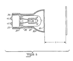
- the assembled reflector and lamp is illustrated in Figure 5.
- the luminous intensity of the radiant flux emitted from between the electrode 9, 11 and focused at the focal point 39 is detected at point locations in a plane normal to the central axis and positioned at or near the focal point 39, as illustrated in Figure 5.
- the plots of luminous intensity detected at such points in a plane that is positioned at various distances from the electrodes 9, 11 are illustrated in the graphs of Figures 6 and 7. Specifically, Figure 6 illustrates the luminous intensity at points in the horizontal plane which intersects the electrodes 9, 11 at various distances therefrom, and Figure 7 illustrates luminous intensity or points in the vertical plane intermediate the electrodes 9, 11 at various distances therefrom.
- the distribution of luminous intensities is centrally peaked at the focal distance, and that the distribution is substantially symmetrical in the horizontal plane (as illustrated in Figure 6). However, the intensity distribution is asymmetrical in the vertical plane (as illustrated in Figure 7) with the supplemental peaks of luminous intensities peaking at locations above the horizontal plane that intersect the electrodes 9, 11 where the detecting distance, d, of Figure 5 is less than or equal to the focal distance (about 1.0").
- Applicant believes that one explanation for asymmetrical intensity distribution is that ionizable gases within bulb 13 including metal-vapors tend to condense and pool dominantly in the lower region of the bulb 13 to varying degrees with increased operating time. Thus, radiant flux emitted from the lower portion of the bulb 13 is thereby partly attenuated or occluded. Because of this effect on the total flux radiated from between the electrodes 9, 11, the axis of electrodes 9, 11 is displaced slightly in the negative or downward direction relative to the axis of symmetry of the reflective section 33 to slightly shift the peak in the vertical distribution.
- the electrode axis 14 is displaced below the axis of symmetry of the reflector section 33 by a selected dimension, and the base 23 is then attached or permanently affixed to the mounting section 37, for example, using a glass-to-glass weld, or conventional epoxy or frit-glass adhesives 36, or the like.
- the selected displacement dimension is believed to be dependent upon the diameter, D, of gas filled bulb 13 illustrated in Figure 2. Therefore, the displacement of the electrodes 9, 11 relative to the axis of symmetry is set at about n x D, where 0 ⁇ n ⁇ 0.2.
- the total flux intensity detected at the focal point 39 is thus maximized, and the base 23 and mounting section 37 are rigidly and permanently attached together to provide the lamp assembly, as illustrated in Figure 5, that retains a preferred operating orientation (i.e., with electrode axis 14 horizontal) for providing maximum flux intensity at the focal point 39 (at which the ends of optical fibers are positioned).
- the attachment of the base 23 to the mounting section 37 of the reflector greatly facilitates differential thermal expansions at the cooler remote ends of the lamp and reflector that are removed from the source of heat in the region of the ionized discharge between electrodes 9, 11.
- dichroic filters are formed on a transparent glass face plate 61 that is attached to the outer truncation of the reflector section 33, as illustrated in Figure 5, as well as on the inner surfaces of the reflector section 33.
- Dichroic filters are formed in conventional manner (for example, using metal vapor deposition techniques) on these surfaces to provide wavelength-selective transmission through the face plate 61, as illustrated in Figure 8A, and to provide wavelength-selective reflection from the surfaces of the reflector section 33. Resultant emitted radiation from the assembly of Figure 5 is therefore enhanced in the visible range and substantially attenuated in the infrared and ultraviolet ranges, as illustrated in Figure 8A.
- the transmission characteristics of the dichroic filter coating on the faceplate 61 cut off or inhibits the transmission of wavelengths in the infrared and ultraviolet ranges, as illustrated in Figure 8A and 8B. Also, the transmission characteristics of the dichroic filter coating on the reflector section 33 transmits (i.e., does not reflect) the wavelengths in the infrared range, as show in Figure 8C.
- the resultant radiation received by optical fibers positioned at the focal point 39 of the light source of the present invention is therefore significantly less deleterious to the plastic materials of optical fibers due to diminished heat and ultraviolet radiation from the light source of the present invention.
- the light source of the present invention is ideally suited for illuminating the ends of optical fibers positioned at or near the focal point of a truncated ellipsoid.
- the intensity of visible radiation supplied to such focal point is maximized via the alignment procedure previously described, and the intensity of undesirable radiation is attenuated by forming dichroic filters or radiation reflective and transmissive components in the assembly.
Landscapes
- Physics & Mathematics (AREA)
- General Physics & Mathematics (AREA)
- Optics & Photonics (AREA)
- Engineering & Computer Science (AREA)
- General Engineering & Computer Science (AREA)
- Optical Couplings Of Light Guides (AREA)
- Non-Portable Lighting Devices Or Systems Thereof (AREA)
- Discharge Lamps And Accessories Thereof (AREA)
- Investigating Or Analysing Materials By Optical Means (AREA)
- Vessels And Coating Films For Discharge Lamps (AREA)
Applications Claiming Priority (2)
| Application Number | Priority Date | Filing Date | Title |
|---|---|---|---|
| US07/410,860 US5016152A (en) | 1989-09-21 | 1989-09-21 | Focused light source and method |
| US410860 | 1999-10-01 |
Publications (2)
| Publication Number | Publication Date |
|---|---|
| EP0418535A2 true EP0418535A2 (de) | 1991-03-27 |
| EP0418535A3 EP0418535A3 (en) | 1991-09-11 |
Family
ID=23626535
Family Applications (1)
| Application Number | Title | Priority Date | Filing Date |
|---|---|---|---|
| EP19900115240 Withdrawn EP0418535A3 (en) | 1989-09-21 | 1990-08-08 | Focused light source and method |
Country Status (8)
| Country | Link |
|---|---|
| US (1) | US5016152A (de) |
| EP (1) | EP0418535A3 (de) |
| JP (1) | JPH03138610A (de) |
| KR (1) | KR930007437B1 (de) |
| CN (1) | CN1050435A (de) |
| AU (1) | AU633140B2 (de) |
| BR (1) | BR9004568A (de) |
| CA (1) | CA2022936A1 (de) |
Families Citing this family (24)
| Publication number | Priority date | Publication date | Assignee | Title |
|---|---|---|---|---|
| GB2250354A (en) * | 1990-08-18 | 1992-06-03 | Tbl Fibre Optics Limited | Light reflector |
| US5111367A (en) * | 1991-10-16 | 1992-05-05 | Churchill David L | Fiber optic lighting device |
| US5371660A (en) * | 1992-01-31 | 1994-12-06 | Massachusetts Institute Of Technology | Illumination system and method |
| US5560700A (en) * | 1992-01-31 | 1996-10-01 | Massachusetts Institute Of Technology | Light coupler |
| JP2590621Y2 (ja) * | 1992-03-25 | 1999-02-17 | 東陶機器株式会社 | 照明装置付き厨房ユニット |
| US5333228A (en) * | 1993-05-21 | 1994-07-26 | Super Vision International Inc. | Lateral illumination fiber optic cable device and method of manufacture |
| US5838860A (en) * | 1993-05-21 | 1998-11-17 | Super Vision International, Inc. | Fiber optic light source apparatus and method |
| US5528714A (en) * | 1994-09-23 | 1996-06-18 | Super Vision International, Inc. | Fiber optics light source with adjustable mounting, replaceable color wheel elements and cooling |
| US5653519A (en) * | 1993-12-16 | 1997-08-05 | Glass Illuminations, Inc. | Fiber optics illuminator system |
| US6160938A (en) * | 1999-04-15 | 2000-12-12 | Little, Jr.; William D. | Concentric lay stranding for optical fiber cable |
| US20020101816A1 (en) * | 1999-05-20 | 2002-08-01 | Michael F. Braitberg | Removable optical storage device and system |
| US6422730B1 (en) | 2000-03-17 | 2002-07-23 | Super Vision International, Inc. | Fiber optic light source with two chamber cooling |
| DE10044683A1 (de) * | 2000-09-08 | 2002-03-21 | Philips Corp Intellectual Pty | Gasentladungslampe |
| US7343191B1 (en) | 2001-12-27 | 2008-03-11 | Fonar Corporation | MRI system |
| JP4274053B2 (ja) * | 2004-06-07 | 2009-06-03 | ウシオ電機株式会社 | 光源装置 |
| JP4670390B2 (ja) * | 2005-02-23 | 2011-04-13 | パナソニック電工株式会社 | 照明装置 |
| US7621646B2 (en) * | 2006-07-05 | 2009-11-24 | Hewlett-Packard Development Company | Curved band-pass filter |
| JP2010530075A (ja) * | 2007-03-20 | 2010-09-02 | クロマ テクノロジー コーポレイション | 光源 |
| JP2009148810A (ja) * | 2007-12-21 | 2009-07-09 | Hitachi Global Storage Technologies Netherlands Bv | はんだ付け方法 |
| US9308051B2 (en) | 2011-11-15 | 2016-04-12 | Smiths Medical Asd, Inc. | Illuminated tubing set |
| US9308323B2 (en) | 2011-11-15 | 2016-04-12 | Smiths Medical Asd, Inc. | Systems and methods for illuminated medical tubing detection and management indicating a characteristic of at least one infusion pump |
| DE102013011066A1 (de) * | 2013-07-03 | 2015-01-08 | Oerlikon Trading Ag, Trübbach | Wärme-Lichttrennung für eine UV-Strahlungsquelle |
| WO2021226749A1 (en) * | 2020-05-09 | 2021-11-18 | Sz Zuvi Technology Co., Ltd. | Apparatuses and methods for drying an object |
| CN113038114B (zh) * | 2021-02-01 | 2022-08-16 | 中国船舶重工集团公司第七0九研究所 | 基于人眼视觉特性的ar仿真系统及方法 |
Family Cites Families (13)
| Publication number | Priority date | Publication date | Assignee | Title |
|---|---|---|---|---|
| US3099403A (en) * | 1959-12-10 | 1963-07-30 | Raymond L Strawick | Light fixture |
| GB1382051A (en) * | 1971-04-24 | 1975-01-29 | Lucas Industries Ltd | Vehicle lamps |
| US3745325A (en) * | 1971-08-17 | 1973-07-10 | Eastman Kodak Co | Photographic light |
| DE2840031A1 (de) * | 1978-09-14 | 1980-04-03 | Patra Patent Treuhand | Anordnung mit hochdruckentladungslampe und reflektor als baueinheit |
| HU180333B (en) * | 1980-03-07 | 1983-02-28 | Egyesuelt Izzolampa | Reflecting mirror for decreasing the luminous rays being in the infrared region |
| CA1147311A (en) * | 1980-03-10 | 1983-05-31 | David O. Tyler | Sealed beam lamp and method of manufacture |
| US4386292A (en) * | 1980-07-02 | 1983-05-31 | Gte Products Corporation | Projection lamp comprising single ended arc discharge lamp and an interference filter |
| DE3125267A1 (de) * | 1981-06-26 | 1983-01-13 | Patra Patent Treuhand | Halogenellipsoidreflektorlampe mit kaltlichtreflektor |
| US4583528A (en) * | 1984-11-08 | 1986-04-22 | Jack Bauman | Examining device with improved optical coupling between the light source and light conductor |
| JPS61212809A (ja) * | 1985-03-15 | 1986-09-20 | Hiroshi Eto | 光カツプリング装置 |
| DE3515879C1 (de) * | 1985-05-03 | 1986-12-11 | Bähren, Heinz Otto, 5653 Leichlingen | Leuchte mit einer Lichtquelle und mit einer wellenlaengenabhaengigen Filtereinrichtung |
| HU198254B (en) * | 1987-03-11 | 1989-08-28 | Tungsram Reszvenytarsasag | Projector lamp |
| JP2722436B2 (ja) * | 1987-04-06 | 1998-03-04 | オリンパス光学工業株式会社 | 照明光学装置 |
-
1989
- 1989-09-21 US US07/410,860 patent/US5016152A/en not_active Expired - Lifetime
-
1990
- 1990-08-08 EP EP19900115240 patent/EP0418535A3/en not_active Withdrawn
- 1990-08-08 CA CA002022936A patent/CA2022936A1/en not_active Abandoned
- 1990-09-06 BR BR909004568A patent/BR9004568A/pt unknown
- 1990-09-13 AU AU62517/90A patent/AU633140B2/en not_active Expired - Fee Related
- 1990-09-20 KR KR1019900014883A patent/KR930007437B1/ko not_active Expired - Lifetime
- 1990-09-21 CN CN90107988A patent/CN1050435A/zh active Pending
- 1990-09-21 JP JP2254026A patent/JPH03138610A/ja active Pending
Also Published As
| Publication number | Publication date |
|---|---|
| JPH03138610A (ja) | 1991-06-13 |
| KR930007437B1 (ko) | 1993-08-10 |
| US5016152A (en) | 1991-05-14 |
| BR9004568A (pt) | 1991-09-10 |
| EP0418535A3 (en) | 1991-09-11 |
| AU6251790A (en) | 1991-03-28 |
| AU633140B2 (en) | 1993-01-21 |
| CA2022936A1 (en) | 1991-03-22 |
| KR910006660A (ko) | 1991-04-29 |
| CN1050435A (zh) | 1991-04-03 |
Similar Documents
| Publication | Publication Date | Title |
|---|---|---|
| US5016152A (en) | Focused light source and method | |
| US7357537B2 (en) | Light source for projector and projection type image display apparatus using thereof | |
| KR101038450B1 (ko) | 조명 장치 및 투사 시스템 | |
| EP0286333A2 (de) | Reflektorsystem | |
| CN1128063A (zh) | 利用椭球面反射镜的光学会聚和收集系统 | |
| US5117312A (en) | Apparatus including concave reflectors and a line of optical fibers | |
| WO1994003759A2 (en) | Toroidal reflectors for optical system | |
| CN1459039A (zh) | 使用双椭球反射镜将光源的光耦合到目标 | |
| KR100392386B1 (ko) | 고압 방전램프, 고압 방전램프 장치 및 조명 장치 | |
| JP3137848B2 (ja) | 光キューブモジュール | |
| WO2002062108A2 (en) | Apparatus for collecting and condensing electromagnetic radiation | |
| NL8201010A (nl) | Elektrische reflektorlamp. | |
| KR100945182B1 (ko) | 반사경 램프 | |
| US5055979A (en) | Gas discharge light source | |
| JPH0521043A (ja) | 照明装置 | |
| CN224175030U (zh) | 一种无影灯 | |
| EP0501668A2 (de) | Verbesserte mit ellipsoidförmigem Reflektor ausgerüstete Lichtquelle | |
| JP5569293B2 (ja) | 光源装置 | |
| JP3277944B2 (ja) | 照明器具 | |
| WO2001007831A2 (en) | Light guide lamps | |
| JP2725911B2 (ja) | 放電管 | |
| US10008379B1 (en) | Infrared recycling incandescent light bulb | |
| JPH0743848Y2 (ja) | 照明具 | |
| JPS63292562A (ja) | 無電極放電灯装置 | |
| JPH0697604B2 (ja) | 無電極放電灯装置 |
Legal Events
| Date | Code | Title | Description |
|---|---|---|---|
| PUAI | Public reference made under article 153(3) epc to a published international application that has entered the european phase |
Free format text: ORIGINAL CODE: 0009012 |
|
| AK | Designated contracting states |
Kind code of ref document: A2 Designated state(s): AT BE CH DE DK ES FR GB GR IT LI LU NL SE |
|
| PUAL | Search report despatched |
Free format text: ORIGINAL CODE: 0009013 |
|
| AK | Designated contracting states |
Kind code of ref document: A3 Designated state(s): AT BE CH DE DK ES FR GB GR IT LI LU NL SE |
|
| 17P | Request for examination filed |
Effective date: 19920212 |
|
| STAA | Information on the status of an ep patent application or granted ep patent |
Free format text: STATUS: THE APPLICATION HAS BEEN WITHDRAWN |
|
| 18W | Application withdrawn |
Withdrawal date: 19930316 |