EP0418543A2 - Luftauslassschiene - Google Patents
Luftauslassschiene Download PDFInfo
- Publication number
- EP0418543A2 EP0418543A2 EP90115370A EP90115370A EP0418543A2 EP 0418543 A2 EP0418543 A2 EP 0418543A2 EP 90115370 A EP90115370 A EP 90115370A EP 90115370 A EP90115370 A EP 90115370A EP 0418543 A2 EP0418543 A2 EP 0418543A2
- Authority
- EP
- European Patent Office
- Prior art keywords
- air outlet
- air
- rail
- chocks
- recesses
- Prior art date
- Legal status (The legal status is an assumption and is not a legal conclusion. Google has not performed a legal analysis and makes no representation as to the accuracy of the status listed.)
- Granted
Links
Images

Classifications
-
- F—MECHANICAL ENGINEERING; LIGHTING; HEATING; WEAPONS; BLASTING
- F24—HEATING; RANGES; VENTILATING
- F24F—AIR-CONDITIONING; AIR-HUMIDIFICATION; VENTILATION; USE OF AIR CURRENTS FOR SCREENING
- F24F13/00—Details common to, or for air-conditioning, air-humidification, ventilation or use of air currents for screening
- F24F13/02—Ducting arrangements
- F24F13/06—Outlets for directing or distributing air into rooms or spaces, e.g. ceiling air diffuser
- F24F13/072—Outlets for directing or distributing air into rooms or spaces, e.g. ceiling air diffuser of elongated shape, e.g. between ceiling panels
Definitions
- the invention relates to an air outlet rail with a continuous air supply channel and with alternately arranged air outlet openings on both sides of its central vertical plane with air outlet directions angled to the vertical plane, the air outlet openings being formed on the inside on both sides of the rail by mutually opposing moldings and moldings.
- Such an air outlet rail in which the air outlet openings are formed by two half rails, which are arranged parallel to one another and extend over the length of the air outlet rail and are interlocked with one another.
- This embodiment is not free from disadvantages because the air outflow openings are neither variable with respect to the air outflow cross section nor with regard to the air outflow direction.
- an air outlet rail consisting of an air duct provided on the underside with openings, the rectangular cross section of which is narrowed on the air outlet side.
- continuous, mirror-inverted profile strips are provided on the outflow side, the cross section of which is Z-shaped, with alternating sequences of C-shaped profile strips covering one or the other Z-profile strip in such a way that curved or angled air ducts extend in the outflow direction forms.
- This embodiment is complex in terms of production technology and costly.
- the invention has for its object to provide an air outlet rail of the type described in the simple and functional design enables different air outlet cross sections and air outlet directions.
- chocks can be used in a rail base body according to the number of air outflow openings, which together with the rail base body form defined air outlet openings. Since the chocks can be formed with different geometries, different air outflow cross sections and air outflow angles or directions can be realized. This applies to every single air outlet opening. Regularly, however, the same air outlet cross sections and air outlet directions will be set up for all air outlet openings depending on the respective application, that is, the same chocks will be used. In any case, the air outlet rail according to the invention is variable with regard to the air outlet cross sections and air outlet direction.
- the invention provides that the chocks or their formations form a cross section tapering in the outflow direction and consequently a nozzle cross section with the formations of the rail flanks. This means that Realize difficultly defined air outlets.
- the invention recommends that chocks with different angles of inclination of the formation to the lower horizontal plane of the air outlet rail can be used in the installation recesses, thereby forming the tapering nozzle cross section.
- the chocks have a groove which adjoins the air supply duct and divides the molding with a groove base which runs out in an arc towards the air outlet opening in question.
- twisted air jets can be realized with a rotational movement around the axis in the air outflow direction. With such swirled air jets, the exit velocity of the air due to swirling is reduced much faster than with untwisted air jets.
- the mixing of the supply air with the room air is much more intensive.
- a particular advantage of the air outlet rail according to the invention is that at a given air outflow angle with swirled air jets, significantly lower air outflow heights than with non-swirled air jets can be realized, so that either more air can be blown into the room in question at the same ceiling height or the air outlet rail according to the invention with a lower ceiling height than that conventional embodiments can be used when working with the same supply air. While, for example, air outlet rails with untwisted air jets and a predetermined air outflow angle can only be used from 2.7 m to 2.8 m, the invention can be Install the appropriate air outlet rail as a result of the swirled air jets from a ceiling height of 2.4 m, without drafts occurring in the case of air conditioning and especially in the case of cooling.
- the mouths of the air outlet openings can be arranged in the entire region of the air outlet rail and have a predetermined inclination to the horizontal plane.
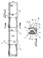
- an air outlet rail 1 is shown with a continuous air supply duct 2 and with air outlet openings 3 arranged alternately on both sides of its central vertical plane V with air outlet directions angled to the vertical plane V.
- the air outflow openings 3 are formed on the inside on both rail flanks 6 by mutually opposing recesses 4 and recesses 5.
- Such an air outlet rail 1 is regularly used for blowing supply air into rooms to be ventilated, and is preferably used in the ceiling area.
- the formations are designed as replaceable chocks 5.
- the two rail flanks 6 alternately have installation recesses 7 for inserting the chocks 5 aligned with the outside rail profile.
- the chocks 5 can be snapped or clamped into the recesses 7, for example.
- the chocks 5 or formations, together with the formations 4, form a nozzle cross section that tapers in the air outflow direction.
- the indentations 4 have a predetermined angle of inclination ⁇ to the lower horizontal plane H of the air outlet rail 1.
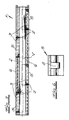
- chocks 5 with different angles of inclination ⁇ of the formations 5 to the lower horizontal plane H of the air outlet rail 1 can be inserted into the recesses 7.
- the air outflow and consequently nozzle cross section can be varied as well as the air outflow direction or the air outflow angle.
- the chocks 5 have a groove 8, which adjoins the air supply duct 2 and divides the respective molding, with a groove bottom which runs out in an arc shape towards the air outlet opening 3 in question. This results in a swirling or swirling of the emerging air jets.
- the orifices 9 of the air outflow openings 3 lie in the edge region of the air outlet rail 1 and have a predetermined inclination to the horizontal plane H, so that there is no fear of mutual interference between the emerging air jets.
Landscapes
- Engineering & Computer Science (AREA)
- Chemical & Material Sciences (AREA)
- Combustion & Propulsion (AREA)
- Mechanical Engineering (AREA)
- General Engineering & Computer Science (AREA)
- Duct Arrangements (AREA)
- Air-Flow Control Members (AREA)
Abstract
Description
- Die Erfindung betrifft eine Luftauslaßschiene mit einem durchlaufenden Luftzuführungskanal und mit beidseitig seiner mittleren Vertikalebene wechselweise angeordneten Luftausströmöffnungen mit zur Vertikalebene abgewinkelten Luftausströmrichtungen, wobei die Luftausströmöffnungen durch sich wechselweise gegenüberliegende Einformungen und Ausformungen innenseitig an beiden Schienenflanken gebildet sind.
- Es ist eine derartige Luftauslaßschiene bekannt, bei welcher die Luftausströmöffnungen durch zwei sich über die Länge der Luftauslaßschiene erstreckende, parallel zueinander angeordnete, ineinander verzahnte Halbschienen gebildet sind. Diese Ausführungsform ist nicht frei von Nachteilen, weil die Luftausströmöffnungen weder in bezug auf den Luftausströmquerschnitt noch hinsichtlich der Luftausströmrichtung variabel sind.
- Ferner kennt man eine Luftauslaßschiene, bestehend aus einem unterseitig mit Durchbrüchen versehenen Luftkanal, dessen rechteckiger Querschnitt luftaustrittsseitig verengt ist. An beiden Längsseiten des Luftkanals sind ausströmseitig durchgehende, spiegelbildlich angeordnete Profilleisten vorgesehen, deren Querschnitt Z-förmig ausgebildet ist, wobei in wechselnder Folge C-förmige Profilleisten die eine oder andere Z-Profilleiste so abdecken, daß sich in Ausströmrichtung en gekrümmter bzw. abgewinkelter Luftkanal bildet. Diese Ausführungsform ist in fertigungstechnischer Hinsicht aufwendig und kostenaufwendig.
- Der Erfindung liegt die Aufgabe zugrunde, eine Luftauslaßschiene der eingangs beschriebenen Art zu schaffen, die in einfacher und funktionsgerechter Bauweise unterschiedliche Luftausströmquerschnitte und Luftausströmrichtungen ermöglicht.
- Diese Aufgabe löst die Erfindung bei einer gattungsgemäßen Luftauslaßschiene dadurch, daß die Ausformungen als auswechselbare Einbaustücke ausgebildet sind und die beiden Schienenflanken wechselweise Einbauausnehmungen zum Einsetzen der mit dem außenseitigen Schienenprofil fluchtenden Einbaustücke aufweisen. - Diese Maßnahmen der Erfindung haben zur Folge, daß sich in einen Schienengrundkörper Einbaustücke entsprechend der Anzahl der Luftausströmöffnungen einsetzen lassen, die mit dem Schienengrundkörper gemeinsam definierte Luftausströmöffnungen bilden. Da die Einbaustücke mit Ausformungen unterschiedlicher Geometrie ausgebildet sein können, lassen sich unterschiedliche Luftausströmquerschnitte und Luftausströmwinkel bzw. -richtungen verwirklichen. Das gilt für jede einzelne Luftausströmöffnung. Regelmäßig wird man allerdings bei sämtlichen Luftausströmöffnungen in Abhängigkeit von dem jeweiligen Anwendungsfall die dann gleichen Luftausströmquerschnitte und Luftausströmrichtungen einrichten, also die gleichen Einbaustücke verwenden. Jedenfalls ist die erfindungsgemäße Luftauslaßschiene hinsichtlich der Luftausströmquerschnitte und Luftausströmrichtung variabel.
- Weitere erfindungswesentliche Merkmale sind im folgenden aufgeführt. So sieht die Erfindung vor, daß die Einbaustücke bzw. ihre Ausformungen mit den Einformungen der Schienenflanken einen sich in Ausströmrichtung verjüngenden Querschnitte und folglich Düsenquerschnitt bilden. Dadurch lassen sich un schwer definierte Luftausströmschlitze verwirklichen. Bei einer Luftauslaßschiene, bei welcher die Einformungen einen vorgegebenen Neigungswinkel zur unteren Horizontalebene der Luftauslaßschiene aufweisen, empfiehlt die Erfindung, daß in die Einbauausnehmungen Einbaustücke mit unterschiedlichem Neigungswinkel der Ausformung zur unteren Horizontalebene der Luftauslaßschiene einsetzbar sind und dadurch der sich verjüngende Düsenquerschnitt gebildet wird.
- Nach einem Vorschlag der Erfindung, dem selbständige Bedeutung zukommt, ist vorgesehen, daß die Einbaustücke eine sich an den Luftzuführungskanal anschließende und die Anformung teilende Nut mit einem gegen die betreffende Luftausströmöffnung bogenförmig auslaufenden Nutengrund aufweisen. Dadurch lassen sich gleichsam verdrallte Luftstrahlen mit einer Rotationsbewegung um die Achse in Luftausströmrichtung verwirklichen. Bei derart verdrallten Luftstrahlen wird die Austrittsgeschwindigkeit der Luft infolge Verwirbelung sehr viel schneller abgebaut als bei unverdrallten Luftstrahlen. Außerdem ist die Vermischung der Zuluft mit der Raumluft sehr viel intensiver. Ein besonderer Vorteil der erfindungsgemäßen Luftauslaßschiene besteht darin, daß bei vorgegebenem Luftausströmwinkel mit verdrallten Luftstrahlen wesentlich niedrigere Luftausströmhöhen als bei unverdrallten Luftstrahlen realisierbar sind, so daß entweder bei gleicher Deckenhöhe mehr Zuluft in den betreffenden Raum eingeblasen werden kann oder die erfindungsgemäße Luftauslaßschiene bei niedrigerer Deckenhöhe als die herkömmlichen Ausführungsformen eingesetzt werden kann, wenn mit gleicher Zuluft gearbeitet wird. Während beispielsweise Luftauslaßschienen mit unverdrallten Luftstrahlen und vorgegebenem Luftausströmwinkel erst ab 2,7m bis 2,8 m eingesetzt werden können, läßt sich die erfindungs gemäße Luftauslaßschiene infolge der verdrallten Luftstrahlen bereits ab Deckenhöhen von 2,4 m einbauen, ohne daß im Klimatisierungsfall und hier insbesondere im Kühlfall Zugerscheinungen auftreten. Tatsächlich werden mittels der verdrallten Luftstrahlen Temperaturdifferenzen schnell abgebaut, so daß ein homogenes Temperaturniveau im gesamten Aufenthaltsbereich von ca. 1,8 m gewährleistet ist. - Im übrigen können bei der erf indungsgemäßen Luftauslaßschiene die Mündungen der Luftausströmöffnungen im ganzen Bereich der Luftauslaßschiene angeordnet sein und eine vorgegebene Neigung zur Horizontalebene aufweisen.
- Im folgenden wird die Erfindung anhand einer lediglich ein Ausführungsbeispiel darstellenden Zeichnung näher erläutert; es zeigen:
- Fig. 1 eine erfindungsgemäße Luftauslaßschiene in schematischer Seitenansicht,
- Fig. 2 einen Querschnitt A-A durch den Gegenstand nach Fig. 1,
- Fig. 3 eine ausschnittsweise Ansicht von unten auf den Gegenstand nach Fig. 1,
- Fig. 4 eine abgewandelte Ausführungsform des Gegenstandes nach Fig. 1 in Seitenansicht,
- Fig. 5 einen Querschnitt B-B durch den Gegenstand nach Fig. 4 und
- Fig. 6 ein Einbaustück für den Gegenstand nach Fig. 4 in Seitenansicht.
- In den Figuren ist eine Luftauslaßschiene 1 mit einem durchlaufenden Luftzuführungskanal 2 und mit beidseitig seiner mittleren Vertikalebene V wechselweise angeordneten Luftausströmöffnungen 3 mit zur Vertikalebene V abgewinkelten Luftausströmrichtungen dargestellt.
- Die Luftausströmöffnungen 3 sind durch sich wechselweise gegenüberliegende Einformungen 4 und Ausformungen 5 innenseitig an beiden Schienenflanken 6 gebildet. Eine derartige Luftauslaßschiene 1 findet regelmäßig zum Einblasen von Zuluft in zu belüftende Räume Verwendung, und wird vorzugsweise im Dekkenbereich eingesetzt. Die Ausformungen sind als auswechselbare Einbaustücke 5 ausgebildet. Die beiden Schienenflanken 6 weisen dazu wechselweise Einbauausnehmungen 7 zum Einsetzen der mit dem außenseitigen Schienenprofil fluchtenden Einbaustücke 5 auf. Die Einbaustücke 5 lassen sich in die Einbauausnehmungen 7 beispielsweise einrasten oder einklemmen. Die Einbaustücke 5 bzw. Ausformungen bilden mit den Einformungen 4 einen sich in Luftausströmrichtung verjüngenden Düsenquerschnitt. Die Einformungen 4 weisen einen vorgegebenen Neigungswinkel α zur unteren Horizontalebene H der Luftauslaßschiene 1 auf. Dagegen sind in die Einbauausnehmungen 7 Einbaustücke 5 mit unterschiedlichem Neigungswinkel β der Ausformungen 5 zur unteren Horizontalebene H der Luftauslaßschine 1 einsetzbar. Dadurch läßt sich der Luftausström- und folglich Düsenquerschnitt ebenso variieren wie die Luftausströmrichtung bzw. der Luftausströmwinkel.
- Nach einer bevorzugten Ausführungsform weisen die Einbaustücke 5 eine sich an den Luftzuführungskanal 2 anschließende und die jeweilige Anformung teilende Nut 8 mit einem gegen die betreffende Luftausströmöffnung 3 bogenförmig auslaufenden Nutengrund auf. Dadurch wird eine Verwirbelung bzw. Verdrallung der austretenden Luftstrahlen erreicht. Die Mündungen 9 der Luftausströmöffnungen 3 liegen im Kantenbereich der Luftauslaßschiene 1 und weisen eine vorgegebene Neigung zur Horizontalebene H auf, so daß eine gegenseitige Beeinflussung der austretenden Luftstrahlen nicht zu befürchten ist.
Claims (5)
Applications Claiming Priority (2)
| Application Number | Priority Date | Filing Date | Title |
|---|---|---|---|
| DE3931459 | 1989-09-21 | ||
| DE19893931459 DE3931459C1 (de) | 1989-09-21 | 1989-09-21 |
Publications (3)
| Publication Number | Publication Date |
|---|---|
| EP0418543A2 true EP0418543A2 (de) | 1991-03-27 |
| EP0418543A3 EP0418543A3 (en) | 1991-07-17 |
| EP0418543B1 EP0418543B1 (de) | 1992-10-28 |
Family
ID=6389854
Family Applications (1)
| Application Number | Title | Priority Date | Filing Date |
|---|---|---|---|
| EP19900115370 Expired - Lifetime EP0418543B1 (de) | 1989-09-21 | 1990-08-10 | Luftauslassschiene |
Country Status (3)
| Country | Link |
|---|---|
| EP (1) | EP0418543B1 (de) |
| DE (1) | DE3931459C1 (de) |
| ES (1) | ES2035689T3 (de) |
Cited By (1)
| Publication number | Priority date | Publication date | Assignee | Title |
|---|---|---|---|---|
| EP0663574A3 (de) * | 1994-01-18 | 1996-02-14 | Krantz Tkt Gmbh | Induktiver Luftdurchlass. |
Families Citing this family (1)
| Publication number | Priority date | Publication date | Assignee | Title |
|---|---|---|---|---|
| DE4305471C2 (de) * | 1993-02-24 | 1997-06-19 | Fritz Juergen Eidmann | Deckenluftauslaß, insbesondere Luftauslaßschiene |
Family Cites Families (5)
| Publication number | Priority date | Publication date | Assignee | Title |
|---|---|---|---|---|
| DE7510290U (de) * | 1975-07-24 | Schuld H | Kondensatableiter | |
| DE7510280U (de) * | 1975-04-02 | 1975-08-21 | Krantz H | Luftauslass |
| DE2716254C2 (de) * | 1977-04-13 | 1986-04-10 | H. Krantz Gmbh & Co, 5100 Aachen | Luftauslaß mit in einer Reihe angeordneten Auslaßöffnungen |
| DE7828982U1 (de) * | 1978-09-29 | 1979-01-18 | H. Krantz Gmbh & Co, 5100 Aachen | Linearer luftauslass |
| DE3731491C1 (en) * | 1987-09-18 | 1989-03-09 | Kiefer Gmbh Maschf G G | Elongated air distributor |
-
1989
- 1989-09-21 DE DE19893931459 patent/DE3931459C1/de not_active Expired - Lifetime
-
1990
- 1990-08-10 EP EP19900115370 patent/EP0418543B1/de not_active Expired - Lifetime
- 1990-08-10 ES ES90115370T patent/ES2035689T3/es not_active Expired - Lifetime
Cited By (1)
| Publication number | Priority date | Publication date | Assignee | Title |
|---|---|---|---|---|
| EP0663574A3 (de) * | 1994-01-18 | 1996-02-14 | Krantz Tkt Gmbh | Induktiver Luftdurchlass. |
Also Published As
| Publication number | Publication date |
|---|---|
| DE3931459C1 (de) | 1991-02-21 |
| ES2035689T3 (es) | 1993-04-16 |
| EP0418543A3 (en) | 1991-07-17 |
| EP0418543B1 (de) | 1992-10-28 |
Similar Documents
| Publication | Publication Date | Title |
|---|---|---|
| EP0615098B1 (de) | Vorrichtung zum Abscheiden von Partikeln, insbesondere Öl- oder Fettpartikeln | |
| EP0361213B1 (de) | Luftauslass für Innenräume, insbesondere für den Innenraum eines Kraftfahrzeuges | |
| EP0418543B1 (de) | Luftauslassschiene | |
| DE3309393A1 (de) | Zuluftverteiler | |
| DE2033195C3 (de) | Luftaustrittseinrichtung für Klimaanlagen | |
| EP2996923B1 (de) | Luftauslass | |
| DE9400738U1 (de) | Konvektives Kühlelement | |
| DE4305471C2 (de) | Deckenluftauslaß, insbesondere Luftauslaßschiene | |
| DE19626884C2 (de) | Luftauslaß | |
| DE2346108C3 (de) | Schienenartiges Luftauslaßelement für Raumbelüftungsanlagen | |
| EP0239854B1 (de) | Luftauslass | |
| DE19912567B4 (de) | Luftleiteinrichtung für einen Luftdurchlaß | |
| DE1289288B (de) | Wand- oder Deckenverkleidung oder Unterdecke, insbesondere belueftete und/oder akustische Verkleidung oder Unterdecke | |
| DE2701845C3 (de) | Vorrichtung zur Bildung eines Luftvorhanges an Portalen | |
| DE2525196A1 (de) | Schlitzauslass | |
| DE3527472A1 (de) | Luftauslasskammer fuer die raumbelueftung | |
| DE19937573C1 (de) | Luftauslaß | |
| EP0526553B1 (de) | Luftzuführungseinrichtung | |
| EP4224077A1 (de) | Luftdurchlass | |
| DE3536810C1 (en) | Device for the air-conditioning of rooms | |
| DE2525977A1 (de) | Lueftungsgitter fuer die belueftung von innenraeumen | |
| DE7707187U1 (de) | Vorrichtung zum linienfoermigen einblasen von zuluft in einen gebaeuderaum | |
| DE2106186C3 (de) | Fußbodenluftauslaß fur Klimaanlagen | |
| DE2236103A1 (de) | Luftauslass fuer lueftungsanlagen | |
| DE102007052205B4 (de) | Luftauslassdüse für eine Trennstrahlanlage und Düsenstrang |
Legal Events
| Date | Code | Title | Description |
|---|---|---|---|
| PUAI | Public reference made under article 153(3) epc to a published international application that has entered the european phase |
Free format text: ORIGINAL CODE: 0009012 |
|
| AK | Designated contracting states |
Kind code of ref document: A2 Designated state(s): CH ES FR IT LI |
|
| PUAL | Search report despatched |
Free format text: ORIGINAL CODE: 0009013 |
|
| AK | Designated contracting states |
Kind code of ref document: A3 Designated state(s): CH ES FR IT LI |
|
| 17P | Request for examination filed |
Effective date: 19910801 |
|
| 17Q | First examination report despatched |
Effective date: 19920409 |
|
| GRAA | (expected) grant |
Free format text: ORIGINAL CODE: 0009210 |
|
| AK | Designated contracting states |
Kind code of ref document: B1 Designated state(s): CH ES FR IT LI |
|
| ITF | It: translation for a ep patent filed | ||
| ET | Fr: translation filed | ||
| REG | Reference to a national code |
Ref country code: ES Ref legal event code: FG2A Ref document number: 2035689 Country of ref document: ES Kind code of ref document: T3 |
|
| PLBE | No opposition filed within time limit |
Free format text: ORIGINAL CODE: 0009261 |
|
| STAA | Information on the status of an ep patent application or granted ep patent |
Free format text: STATUS: NO OPPOSITION FILED WITHIN TIME LIMIT |
|
| 26N | No opposition filed | ||
| PGFP | Annual fee paid to national office [announced via postgrant information from national office to epo] |
Ref country code: FR Payment date: 19940527 Year of fee payment: 5 |
|
| PGFP | Annual fee paid to national office [announced via postgrant information from national office to epo] |
Ref country code: ES Payment date: 19940810 Year of fee payment: 5 |
|
| PGFP | Annual fee paid to national office [announced via postgrant information from national office to epo] |
Ref country code: CH Payment date: 19940822 Year of fee payment: 5 |
|
| PG25 | Lapsed in a contracting state [announced via postgrant information from national office to epo] |
Ref country code: ES Free format text: LAPSE BECAUSE OF THE APPLICANT RENOUNCES Effective date: 19950811 |
|
| PG25 | Lapsed in a contracting state [announced via postgrant information from national office to epo] |
Ref country code: LI Effective date: 19950831 Ref country code: CH Effective date: 19950831 |
|
| REG | Reference to a national code |
Ref country code: CH Ref legal event code: PL |
|
| PG25 | Lapsed in a contracting state [announced via postgrant information from national office to epo] |
Ref country code: FR Effective date: 19960430 |
|
| REG | Reference to a national code |
Ref country code: FR Ref legal event code: ST |
|
| REG | Reference to a national code |
Ref country code: ES Ref legal event code: FD2A Effective date: 19991007 |
|
| PG25 | Lapsed in a contracting state [announced via postgrant information from national office to epo] |
Ref country code: IT Free format text: LAPSE BECAUSE OF NON-PAYMENT OF DUE FEES;WARNING: LAPSES OF ITALIAN PATENTS WITH EFFECTIVE DATE BEFORE 2007 MAY HAVE OCCURRED AT ANY TIME BEFORE 2007. THE CORRECT EFFECTIVE DATE MAY BE DIFFERENT FROM THE ONE RECORDED. Effective date: 20050810 |