EP0418628A1 - Fussstück mit verbessertem Teilchenfilter für Kernbrennelemente - Google Patents
Fussstück mit verbessertem Teilchenfilter für Kernbrennelemente Download PDFInfo
- Publication number
- EP0418628A1 EP0418628A1 EP90116883A EP90116883A EP0418628A1 EP 0418628 A1 EP0418628 A1 EP 0418628A1 EP 90116883 A EP90116883 A EP 90116883A EP 90116883 A EP90116883 A EP 90116883A EP 0418628 A1 EP0418628 A1 EP 0418628A1
- Authority
- EP
- European Patent Office
- Prior art keywords
- bottom nozzle
- filter bottom
- debris filter
- debris
- cylindrical sections
- Prior art date
- Legal status (The legal status is an assumption and is not a legal conclusion. Google has not performed a legal analysis and makes no representation as to the accuracy of the status listed.)
- Granted
Links
Images

Classifications
-
- G—PHYSICS
- G21—NUCLEAR PHYSICS; NUCLEAR ENGINEERING
- G21C—NUCLEAR REACTORS
- G21C3/00—Reactor fuel elements and their assemblies; Selection of substances for use as reactor fuel elements
- G21C3/30—Assemblies of a number of fuel elements in the form of a rigid unit
- G21C3/32—Bundles of parallel pin-, rod-, or tube-shaped fuel elements
- G21C3/3206—Means associated with the fuel bundle for filtering the coolant, e.g. nozzles, grids
-
- G—PHYSICS
- G21—NUCLEAR PHYSICS; NUCLEAR ENGINEERING
- G21C—NUCLEAR REACTORS
- G21C3/00—Reactor fuel elements and their assemblies; Selection of substances for use as reactor fuel elements
- G21C3/30—Assemblies of a number of fuel elements in the form of a rigid unit
-
- G—PHYSICS
- G21—NUCLEAR PHYSICS; NUCLEAR ENGINEERING
- G21C—NUCLEAR REACTORS
- G21C3/00—Reactor fuel elements and their assemblies; Selection of substances for use as reactor fuel elements
- G21C3/30—Assemblies of a number of fuel elements in the form of a rigid unit
- G21C3/32—Bundles of parallel pin-, rod-, or tube-shaped fuel elements
-
- G—PHYSICS
- G21—NUCLEAR PHYSICS; NUCLEAR ENGINEERING
- G21C—NUCLEAR REACTORS
- G21C19/00—Arrangements for treating, for handling, or for facilitating the handling of, fuel or other materials which are used within the reactor, e.g. within its pressure vessel
- G21C19/28—Arrangements for introducing fluent material into the reactor core; Arrangements for removing fluent material from the reactor core
- G21C19/30—Arrangements for introducing fluent material into the reactor core; Arrangements for removing fluent material from the reactor core with continuous purification of circulating fluent material, e.g. by extraction of fission products deterioration or corrosion products, impurities, e.g. by cold traps
- G21C19/307—Arrangements for introducing fluent material into the reactor core; Arrangements for removing fluent material from the reactor core with continuous purification of circulating fluent material, e.g. by extraction of fission products deterioration or corrosion products, impurities, e.g. by cold traps specially adapted for liquids
-
- Y—GENERAL TAGGING OF NEW TECHNOLOGICAL DEVELOPMENTS; GENERAL TAGGING OF CROSS-SECTIONAL TECHNOLOGIES SPANNING OVER SEVERAL SECTIONS OF THE IPC; TECHNICAL SUBJECTS COVERED BY FORMER USPC CROSS-REFERENCE ART COLLECTIONS [XRACs] AND DIGESTS
- Y02—TECHNOLOGIES OR APPLICATIONS FOR MITIGATION OR ADAPTATION AGAINST CLIMATE CHANGE
- Y02E—REDUCTION OF GREENHOUSE GAS [GHG] EMISSIONS, RELATED TO ENERGY GENERATION, TRANSMISSION OR DISTRIBUTION
- Y02E30/00—Energy generation of nuclear origin
- Y02E30/30—Nuclear fission reactors
Definitions
- the present invention relates generally to nuclear reactors and, more particularly, to an enhanced debris filter bottom nozzle for a nuclear fuel assembly.
- Applicant's U.S. Patent No. 4,096,032 discloses an in-core flow filter adapted to be temporarily placed over the coolant flow openings of the lower core plate during functional testing of the reactor's primary cooling system, and then, when testing is completed, to be removed therefrom together with any filtered-out debris.
- Applicant's EP-B-0 184 219, EP-A-0 196 611 and EP-A-0 213 813 disclose debris traps adapted to be installed within, as in EP-B-0 184 219 and Ep A-0 196 611, or directly above, as in EP-A-0 213 813, the bottom nozzles of fuel assemblies, and to remain there throughout a whole fuel cycle.
- the present invention has for its principal objective to provide an enhanced debris-filter bottom-nozzle capable of still finer debris filtration and lending itself to being produced at reasonable cost and without detriment to its structural strength.
- the invention accordingly resides in a debris filter bottom nozzle including a transverse structure which has extending therethrough a plurality of coolant flow passages sufficiently small in diameter to prevent passage of debris of a predetermined size, characterized in that said transverse structure consists of a consolidated array of cylindrical sections disposed side-by- side in substantially parallel relationship with each other and rigidly connected together.
- this debris filter bottom nozzle embodying the invention resides in that it enables a finer debris filtration to be obtained by reducing the diametric size and increasing the number of tubular sections used in forming the transverse structure, and that, contrary to drilling more holes through a solid bottom nozzle adapter plate and thereby removing material, an increase in the number of tubular sections employed will result in adding material to the transverse structure and, consequently, in increasing its strength. Moreover, it is easier and more economical to produce an enhanced debris filter bottom nozzle by rigidly interconnecting, e.g. brazing, a plurality of cylindrical sections than to drill a large number of small flow passages through an otherwise solid and relatively thick bottom nozzle adapter plate.
- the cylindrical sections may be of at least two different diametric sizes or may all have the same diameter, depending upon such factors as, for example, the degree of debris filtration and the configuration and size desired of the consolidated array. They are at least predominantly tubular sections each defining one of said coolant flow passages therethrough, but some cylindrical solid sections may also be utilized in the array, if desired.
- the array preferably includes a solid bar member of larger diametric size and with a bore formed therein for receiving a lower end portion of the guide thimble associated with the particular thimble location.
- the debris filter bottom nozzle of the invention includes an open frame or peripheral enclosure defining a coolant flow space therethrough, the transverse structure being disposed within and extending across said flow space, and being connected, e.g. braze-jointed, to the peripheral enclosure.
- a preferred method of fabricating the enhanced debris filter bottom nozzle of the invention includes fitting the array of cylindrical sections into the flow space defined by the peripheral enclosure, and then causing the whole assembly consisting of the enclosure and the array of cylindrical sections fit therein to be consolidated, preferably by placing it into a furnace and subjecting it to a brazing operation.
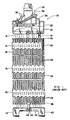
- the fuel assembly illustrated therein and generally designated with numeral 10 is of the type employed in pressurized-water reactors (PWR). Basically, it comprises a lower end structure or bottom nozzle 12 adapted to support the fuel assembly on the lower core plate (not shown) in the core region of a nuclear reactor (not shown), a plurality of control-rod guide tubes or thimbles 14 extending upwards from the bottom nozzle 12, transverse grids 16 spaced axially along the guide thimbles 14 and attached thereto, an organized array of elongate fuel rods 18 laterally supported by the grids 16 in spaced relationship with respect to each other, a centrally located instrumentation tube 20, and an upper end structure or top nozzle 22 removably attached to upper end portions of the guide thimbles 14.
- the fuel assembly 10 thus constructed forms an integral unit lending itself to being conventionally handled without risk of damage to its component parts.
- Each of the fuel rods 18 is hermetically sealed at its opposite ends by means of end plugs 26 and 28, and it contains a stack of pellets 24 made of fissile material as well as a spring 30 disposed between the upper end plug 26 and the pellets 24 for the purpose of keeping the latter firmly stacked.
- the fissile material of the fuel pellets 24 is the source of the reactive power generated during reactor operation, and liquid moderator/coolant, such as water or water containing boron, is pumped through the fuel assemblies within the core of the operating reactor in order to extract therefrom heat for the production of useful work.
- control rods 32 which are axially movable in the various guide thimbles 14 located at predetermined positions within the fuel assembly 10.
- the control rods 32 are supported from a rod cluster control mechanism 34 which is positioned above the top nozzle 22 and includes an internally threaded cylindrical member 36 having radial flukes or arms 38 each having connected thereto one of the control rod 32, the control mechanism 34 being operable to effect the desired control movements of the control rods in the various guide thimbles 14, all as well known in the art.
- the conventional bottom nozzle 12 shown therein comprises a rectangular and substantially planar adapter plate 42, and corner legs 40 connected to the adapter plate for supporting the fuel assembly 10 on the lower core support plate (not shown) of a nuclear reactor.
- the adapter plate 42 has formed therein a central opening 44 for receiving a lower end portion of the instrumentation tube 20 (Fig. 1), several openings 46 for receiving lower end portions of the respective guide thimbles 14, and a plurality of passages 48 for reactor coolant to flow therethrough.
- a central opening 44 for receiving a lower end portion of the instrumentation tube 20 (Fig. 1)
- several openings 46 for receiving lower end portions of the respective guide thimbles 14, and a plurality of passages 48 for reactor coolant to flow therethrough.
- flow passages 48B of a smaller diameter, such as about 6.25 mm both of which diameters are large enough to pass debris of damage-causing size.
- EP-A-0 289 829 discloses a debris-filter bottom nozzle which, instead of featuring an array of relatively large flow passages, such as found in the conventional bottom nozzle of Fig.
- the present invention overcomes these limitations by constructing an enhanced debris filter bottom nozzle from a plurality of right cylindrical sections arrayed side-by-side to define a multitude of parallel flow passages, and rigidly joined to each other to consolidate the array of cylindrical sections into a plate-like structure constituting the transverse structure of the bottom nozzle.
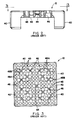
- the enhanced debris filter bottom nozzle embodying the invention and designated herein generally with reference numeral 50 comprises the aforesaid transverse structure 52 constituted by the consolidated array of elongate cylindrical sections 54, and a peripheral frame or enclosure 56 perimetrically embracing the transverse structure 52 which occupies the open coolant flow space 58 defined by the enclosure 56 and is rigidly connected to the latter, the arrangement being such that the transverse structure extends fully across, and the cylindrical sections 54 extend axially in the direction of coolant flow through, the open flow space 58 of the enclosure 56.
- the array of cylindrical sections 54 comprises tubular sections 54A of a larger diameter, and tubular sections 54B of a smaller diameter, each of the tubular sections 54A and 54B defining a coolant flow passage 60 which extends axially therethrough.
- the cylindrical sections 54 are tubular sections all having the same diameter.
- the tubular sections 54, 54A, 54B are thin-walled tubes made of stainless steel and having chamfered ends, as seen from Figs. 5 and 6.
- the transverse structure 52 shown in Fig. 4 includes a solid bar member formed by four solid bar sections 55 rigidly joined cloverleaf-like and having a bore 55A drilled therethrough for receiving a lower end portion of one of the control-rod guide thimbles 14 (Fig. 1).
- the open frame or peripheral enclosure 56 consists of interconnected side walls 62 extending around the transverse structure 52 which preferably has a smaller dimension than the enclosure 56 in the axial direction of the cylindrical sections 54, and may be about as thick as the adapter plate of the conventional debris filter bottom nozzle shown in Fig. 2.
- the peripheral enclosure 56 includes legs 64 for supporting the bottom nozzle 50 on the lower core plate (not shown) of a reactor, the legs 64 being connected to the enclosure 56 at the corners 62A formed by the side walls 62.
- the cylindrical sections 54, the peripheral enclosure 56, and the legs 64 are made of stainless steel and rigidly joined in a single operation.
- a preferred method of fabricating the enhanced debris filter bottom nozzle 50 would include fitting the array of cylindrical sections 54 into the flow space 58 defined by the peripheral enclosure 56, and then consolidating the whole assembly.consisting of the enclosure 56 and the array of cylindrical sections 54 introduced therein, preferably by placing it into a furnace and subjecting it to a brazing operation during which brazing alloy on the cylindrical sections and in strategic areas on the walls 62 of the enclosure 56 is caused to melt and, upon solidification, to bind everything together.
Landscapes
- Physics & Mathematics (AREA)
- Engineering & Computer Science (AREA)
- Plasma & Fusion (AREA)
- General Engineering & Computer Science (AREA)
- High Energy & Nuclear Physics (AREA)
- Structure Of Emergency Protection For Nuclear Reactors (AREA)
- Fuel-Injection Apparatus (AREA)
- Monitoring And Testing Of Nuclear Reactors (AREA)
- Processing Of Solid Wastes (AREA)
- Filtering Materials (AREA)
Applications Claiming Priority (2)
| Application Number | Priority Date | Filing Date | Title |
|---|---|---|---|
| US07/410,574 US5024806A (en) | 1989-09-21 | 1989-09-21 | Enhanced debris filter bottom nozzle for a nuclear fuel assembly |
| US410574 | 1989-09-21 |
Publications (2)
| Publication Number | Publication Date |
|---|---|
| EP0418628A1 true EP0418628A1 (de) | 1991-03-27 |
| EP0418628B1 EP0418628B1 (de) | 1993-03-24 |
Family
ID=23625325
Family Applications (1)
| Application Number | Title | Priority Date | Filing Date |
|---|---|---|---|
| EP90116883A Expired - Lifetime EP0418628B1 (de) | 1989-09-21 | 1990-09-03 | Fussstück mit verbessertem Teilchenfilter für Kernbrennelemente |
Country Status (6)
| Country | Link |
|---|---|
| US (1) | US5024806A (de) |
| EP (1) | EP0418628B1 (de) |
| JP (1) | JP2860377B2 (de) |
| KR (1) | KR910007002A (de) |
| DE (1) | DE69001166D1 (de) |
| ES (1) | ES2041091T3 (de) |
Cited By (4)
| Publication number | Priority date | Publication date | Assignee | Title |
|---|---|---|---|---|
| EP0689211A1 (de) * | 1994-06-24 | 1995-12-27 | General Electric Company | Kernbrennstabbündel mit einem in das Fussstück integrierten Trümmerfilter |
| US9620249B2 (en) | 2007-08-31 | 2017-04-11 | Global Nuclear Fuel—Americas, LLC | Debris shield upper tie plate for nuclear fuel assembly and method to shield assembly from debris |
| CN110537229A (zh) * | 2017-03-17 | 2019-12-03 | 西屋电气有限责任公司 | 核燃料组件碎屑过滤底部喷嘴 |
| CN114898906A (zh) * | 2022-06-09 | 2022-08-12 | 华能核能技术研究院有限公司 | 过球装置和具有其的球床式高温堆 |
Families Citing this family (43)
| Publication number | Priority date | Publication date | Assignee | Title |
|---|---|---|---|---|
| FR2577345B1 (fr) * | 1985-02-08 | 1989-09-22 | Framatome Sa | Dispositif de filtration d'un liquide en circulation dans le circuit de refroidissement d'un reacteur nucleaire et procede de fabrication de ce dispositif |
| FR2664733B1 (fr) * | 1990-07-11 | 1992-11-06 | Framatome Sa | Embout inferieur d'un assemblage combustible pour reacteur nucleaire comportant une plaque adaptatrice et une plaque de filtration accolee a la plaque adaptatrice. |
| FR2682213B1 (fr) * | 1991-10-04 | 1994-01-07 | Framatome | Embout inferieur d'un assemblage combustible pour reacteur nucleaire refroidi a l'eau. |
| US5483564A (en) * | 1993-04-12 | 1996-01-09 | General Electric Company | Lower tie plate strainers including double corrugated strainers for boiling water reactors |
| US5390221A (en) * | 1993-08-23 | 1995-02-14 | General Electric Company | Debris filters with flow bypass for boiling water reactors |
| US5390220A (en) * | 1993-11-29 | 1995-02-14 | General Electric Company | Lower tie plate strainers including helical spring strainers for boiling water reactors |
| US5345483A (en) * | 1993-12-02 | 1994-09-06 | General Electric Company | Lower tie plate strainers having double plate with offset holes for boiling water reactors |
| US5488634A (en) * | 1994-02-10 | 1996-01-30 | General Electric Company | Lower tie plate debris catcher for a nuclear reactor |
| US5473650A (en) * | 1994-04-15 | 1995-12-05 | General Electric Company | Lower tie plate debris catcher for a nuclear reactor |
| US5481577A (en) * | 1994-06-30 | 1996-01-02 | Siemens Power Corporation | Boiling water reactor fuel assembly filter |
| US5539793A (en) * | 1994-10-27 | 1996-07-23 | General Electric Company | Lower tie plate debris catcher for a nuclear reactor |
| US5519745A (en) * | 1994-11-03 | 1996-05-21 | General Electric Company | Lower tie plate debris catcher for a nuclear reactor |
| US5528640A (en) * | 1994-11-07 | 1996-06-18 | General Electric Company | Low pressure double offset plate catcher for a nuclear reactor |
| US5748694A (en) * | 1996-03-26 | 1998-05-05 | General Electric Company | Fuel bundle filter for a nuclear reactor fuel bundle assembly |
| WO1998041767A1 (en) * | 1997-03-19 | 1998-09-24 | Autotrol Corporation | In-line drain flow control |
| ES2275630T3 (es) | 2000-08-01 | 2007-06-16 | General Electric Company | Conjunto de combustible nuclear que comprende un dispositivo de retencion de residuos. |
| US7822165B2 (en) * | 2004-01-05 | 2010-10-26 | Westinghouse Electric Co Llc | Nuclear fuel assembly debris filter bottom nozzle |
| US20070084782A1 (en) * | 2005-10-05 | 2007-04-19 | Enercon Services, Inc. | Filter medium for strainers used in nuclear reactor emergency core cooling systems |
| ITMI20060277U1 (it) * | 2006-07-28 | 2008-01-29 | Rigo S R L | Dispositivo miscelatore,particolarmente per l'erogazione di una resina o di altri prodotti miscelati con un gas espandente |
| US20090060114A1 (en) * | 2007-08-31 | 2009-03-05 | Global Nuclear Fuel - Americas, Llc | Debris shield for upper tie plate in a nuclear fuel bundle and method for filtering debris |
| US8396182B2 (en) * | 2007-08-31 | 2013-03-12 | Global Nuclear Fuel—Americas, LLC | Method and apparatus to shield a nuclear fuel assembly with removable debris shield in upper tie |
| US8548113B2 (en) * | 2009-08-28 | 2013-10-01 | Global Nuclear Fuel - Americas, Llc | Debris mitigation upper tie plates and fuel bundles using the same |
| US20110164719A1 (en) * | 2010-01-05 | 2011-07-07 | Westinghouse Electric Company, Llc | Nuclear fuel assembly debris filter bottom nozzle |
| US9378853B2 (en) | 2010-10-21 | 2016-06-28 | Bwxt Nuclear Energy, Inc. | Support structure for a control rod assembly of a nuclear reactor |
| US9620250B2 (en) | 2012-02-02 | 2017-04-11 | Bwxt Nuclear Energy, Inc. | Spacer grid |
| US9805832B2 (en) | 2012-02-27 | 2017-10-31 | Bwxt Mpower, Inc. | Control rod drive mechanism (CRDM) mounting system for pressurized water reactors |
| US9911512B2 (en) | 2012-02-27 | 2018-03-06 | Bwxt Mpower, Inc. | CRDM internal electrical connector |
| US9959944B2 (en) | 2012-04-12 | 2018-05-01 | Bwxt Mpower, Inc. | Self-supporting radial neutron reflector |
| US10102933B2 (en) | 2012-04-13 | 2018-10-16 | Bwxt Mpower, Inc. | Control rod assembly impact limiter |
| US10124472B2 (en) | 2012-04-16 | 2018-11-13 | Bwxt Mpower, Inc. | Lower end fitting locknut for nuclear fuel assembly |
| US9922731B2 (en) | 2012-04-17 | 2018-03-20 | Bwxt Mpower, Inc. | Resistance welding of an end cap for nuclear fuel rods |
| US9767930B2 (en) | 2012-04-17 | 2017-09-19 | Bwxt Mpower, Inc. | Suspended upper internals for compact nuclear reactor including a mid-hanger plate |
| US9881701B2 (en) | 2012-04-17 | 2018-01-30 | Bwxt Mpower, Inc. | Spacer grids with springs having improved robustness |
| US9666313B2 (en) | 2012-04-17 | 2017-05-30 | Bwxt Mpower, Inc. | Small modular reactor refueling sequence |
| EP2839471B1 (de) | 2012-04-17 | 2017-11-08 | Babcock & Wilcox MPower Inc. | Steigrohrübergangsstück für kompakten kernreaktor |
| CA2870926C (en) | 2012-04-17 | 2021-03-09 | Babcock & Wilcox Mpower, Inc. | Lower end fitting locating pins |
| US9887015B2 (en) | 2012-04-17 | 2018-02-06 | Bwxt Mpower, Inc. | Suspended upper internals with tie rod couplings for compact nuclear reactor |
| CA2870613C (en) | 2012-04-17 | 2021-03-09 | Babcock & Wilcox Mpower, Inc. | Small modular reactor fuel assembly |
| US9754688B2 (en) | 2012-04-17 | 2017-09-05 | Bwx Technologies, Inc. | Suspended upper internals for compact nuclear reactor including a lower hanger plate |
| US9378852B2 (en) | 2012-04-17 | 2016-06-28 | Bwxt Mpower, Inc. | Spacer grids for nuclear reactor |
| US9620253B2 (en) | 2012-04-17 | 2017-04-11 | Bwxt Mpower, Inc. | Riser cone apparatus to provide compliance between reactor components and minimize reactor coolant bypass flow |
| CN104538064B (zh) * | 2014-12-19 | 2017-05-31 | 上海核工程研究设计院 | 一种平衡堆芯入口冷却剂流量的燃料组件下管座 |
| FI4038636T3 (fi) * | 2019-10-04 | 2024-10-25 | Framatome Sa | Ydinpolttoainekokoonpano ja sellaisen ydinpolttoainekokoonpanon valmistusmenetelmä |
Citations (4)
| Publication number | Priority date | Publication date | Assignee | Title |
|---|---|---|---|---|
| EP0213813A2 (de) * | 1985-08-08 | 1987-03-11 | Westinghouse Electric Corporation | Kernbrennstabbündel mit Trümmerfänger |
| EP0289829A2 (de) * | 1987-05-05 | 1988-11-09 | Westinghouse Electric Corporation | Brennelement mit Trümmerfänger-Fussstück |
| DE3832910A1 (de) * | 1987-09-28 | 1989-04-13 | Hitachi Ltd | Kernbrennstoff-abstandshalter vom einzelzellentyp und verfahren fuer dessen herstellung |
| US4832905A (en) * | 1988-04-15 | 1989-05-23 | Combustion Engineering, Inc. | Lower end fitting debris collector |
Family Cites Families (33)
| Publication number | Priority date | Publication date | Assignee | Title |
|---|---|---|---|---|
| US1240081A (en) * | 1917-02-15 | 1917-09-11 | Francis Evan Moss | Apparatus for separating solid matters from fluids or fluids from fluids. |
| US1448151A (en) * | 1921-03-05 | 1923-03-13 | Edwin A Reeves | Commingling device |
| US2825203A (en) * | 1951-08-03 | 1958-03-04 | Snecma | Aerodynamic valves |
| US2688985A (en) * | 1951-08-20 | 1954-09-14 | Daniel Orifice Fitting Company | Orifice fitting device and straightening vane unit assembly |
| DE1074168B (de) * | 1958-03-17 | 1960-01-28 | Westinghouse Electric Corporation, East Pittsburgh, Pa. (V. St. A.) | Spaltstoffelemcnt für heterogene Kernreaktoren, insbesondere für Druckwasserreaktoren |
| US3070534A (en) * | 1958-10-30 | 1962-12-25 | Babcock & Wilcox Co | Fuel elements |
| US3182003A (en) * | 1960-04-04 | 1965-05-04 | Westinghouse Electric Corp | Means for supporting fuel elements in a nuclear reactor |
| US3380890A (en) * | 1964-06-03 | 1968-04-30 | Asea Ab | Spacer for fuel assemblies |
| DE1294574B (de) * | 1965-12-03 | 1969-05-08 | Westinghouse Electric Corp | Auswechselbares Kernreaktor-Brennelement, bestehend aus mehreren Brennstaeben |
| GB1153444A (en) * | 1966-02-22 | 1969-05-29 | Atomic Energy Authority Uk | Transverse Bracing Grids for Clusters of Heat Exchange Elements. |
| SE321998B (de) * | 1966-08-15 | 1970-03-23 | Atomenergi Ab | |
| GB1324192A (en) * | 1970-10-29 | 1973-07-18 | Atomic Energy Authority Uk | Nuclear reactor fuel elements |
| US3840051A (en) * | 1971-03-11 | 1974-10-08 | Mitsubishi Heavy Ind Ltd | Straightener |
| US3801453A (en) * | 1972-02-11 | 1974-04-02 | Transfer Systems | Fuel assembly for power generating nuclear reactor |
| US4038137A (en) * | 1973-09-26 | 1977-07-26 | Exxon Nuclear Company, Inc. | Locking means for fuel bundles |
| CA1032668A (en) | 1974-05-20 | 1978-06-06 | John M. Shallenberger | Modular in-core flow filter for a nuclear reactor |
| US4036692A (en) * | 1975-08-01 | 1977-07-19 | The Babcock & Wilcox Company | Nuclear fuel element nut retainer cup |
| FR2326764A1 (fr) * | 1975-10-02 | 1977-04-29 | Commissariat Energie Atomique | Structure de coeur pour reacteur nucleaire |
| GB1544719A (en) * | 1977-01-12 | 1979-04-25 | British Nuclear Fuels Ltd | Cellular grids |
| US4152206A (en) * | 1977-06-06 | 1979-05-01 | The Babcock & Wilcox Company | Nuclear fuel element end fitting |
| JPS54141989A (en) * | 1978-04-25 | 1979-11-05 | Toshiba Corp | Nuclear fuel assembly |
| US4427624A (en) * | 1981-03-02 | 1984-01-24 | Westinghouse Electric Corp. | Composite nozzle design for reactor fuel assembly |
| IT1170170B (it) * | 1982-07-30 | 1987-06-03 | Westinghouse Electric Corp | Complesso di combustibile nucleare |
| US4508679A (en) * | 1982-08-20 | 1985-04-02 | General Electric Company | Nuclear fuel assembly spacer |
| US4684496A (en) * | 1984-11-16 | 1987-08-04 | Westinghouse Electric Corp. | Debris trap for a pressurized water nuclear reactor |
| US4684495A (en) * | 1984-11-16 | 1987-08-04 | Westinghouse Electric Corp. | Fuel assembly bottom nozzle with integral debris trap |
| FR2577343B1 (fr) * | 1985-02-08 | 1991-03-22 | Commissariat Energie Atomique | Dispositif d'espacement et de maintien de crayons combustibles dans un assemblage combustible |
| US4675154A (en) * | 1985-12-20 | 1987-06-23 | General Electric Company | Nuclear fuel assembly with large coolant conducting tube |
| US4849161A (en) * | 1987-02-19 | 1989-07-18 | Advanced Nuclear Fuels Corp. | Debris-resistant fuel assembly |
| US4781884A (en) * | 1987-03-02 | 1988-11-01 | Combustion Engineering, Inc. | Debris catching strainer grid |
| US4828791A (en) * | 1987-10-05 | 1989-05-09 | Westinghouse Electric Corp. | Nuclear fuel assembly debris resistant bottom nozzle |
| JPH01251787A (ja) * | 1988-03-31 | 1989-10-06 | Toshiba Corp | 電子部品の接続装置 |
| JPH0296891A (ja) * | 1988-10-03 | 1990-04-09 | Omron Tateisi Electron Co | 乗車券販売機 |
-
1989
- 1989-09-21 US US07/410,574 patent/US5024806A/en not_active Expired - Fee Related
-
1990
- 1990-09-03 DE DE9090116883T patent/DE69001166D1/de not_active Expired - Lifetime
- 1990-09-03 EP EP90116883A patent/EP0418628B1/de not_active Expired - Lifetime
- 1990-09-03 ES ES199090116883T patent/ES2041091T3/es not_active Expired - Lifetime
- 1990-09-20 KR KR1019900014956A patent/KR910007002A/ko not_active Withdrawn
- 1990-09-20 JP JP2249016A patent/JP2860377B2/ja not_active Expired - Lifetime
Patent Citations (4)
| Publication number | Priority date | Publication date | Assignee | Title |
|---|---|---|---|---|
| EP0213813A2 (de) * | 1985-08-08 | 1987-03-11 | Westinghouse Electric Corporation | Kernbrennstabbündel mit Trümmerfänger |
| EP0289829A2 (de) * | 1987-05-05 | 1988-11-09 | Westinghouse Electric Corporation | Brennelement mit Trümmerfänger-Fussstück |
| DE3832910A1 (de) * | 1987-09-28 | 1989-04-13 | Hitachi Ltd | Kernbrennstoff-abstandshalter vom einzelzellentyp und verfahren fuer dessen herstellung |
| US4832905A (en) * | 1988-04-15 | 1989-05-23 | Combustion Engineering, Inc. | Lower end fitting debris collector |
Cited By (6)
| Publication number | Priority date | Publication date | Assignee | Title |
|---|---|---|---|---|
| EP0689211A1 (de) * | 1994-06-24 | 1995-12-27 | General Electric Company | Kernbrennstabbündel mit einem in das Fussstück integrierten Trümmerfilter |
| US9620249B2 (en) | 2007-08-31 | 2017-04-11 | Global Nuclear Fuel—Americas, LLC | Debris shield upper tie plate for nuclear fuel assembly and method to shield assembly from debris |
| CN110537229A (zh) * | 2017-03-17 | 2019-12-03 | 西屋电气有限责任公司 | 核燃料组件碎屑过滤底部喷嘴 |
| CN110537229B (zh) * | 2017-03-17 | 2023-08-15 | 西屋电气有限责任公司 | 核燃料组件碎屑过滤底部喷嘴 |
| CN114898906A (zh) * | 2022-06-09 | 2022-08-12 | 华能核能技术研究院有限公司 | 过球装置和具有其的球床式高温堆 |
| CN114898906B (zh) * | 2022-06-09 | 2023-05-16 | 华能核能技术研究院有限公司 | 过球装置和具有其的球床式高温堆 |
Also Published As
| Publication number | Publication date |
|---|---|
| DE69001166D1 (de) | 1993-04-29 |
| JPH03118497A (ja) | 1991-05-21 |
| JP2860377B2 (ja) | 1999-02-24 |
| ES2041091T3 (es) | 1993-11-01 |
| EP0418628B1 (de) | 1993-03-24 |
| KR910007002A (ko) | 1991-04-30 |
| US5024806A (en) | 1991-06-18 |
Similar Documents
| Publication | Publication Date | Title |
|---|---|---|
| EP0418628B1 (de) | Fussstück mit verbessertem Teilchenfilter für Kernbrennelemente | |
| US4900507A (en) | Nuclear fuel assembly debris filter bottom nozzle | |
| EP0289829B1 (de) | Brennelement mit Trümmerfänger-Fussstück | |
| US4828791A (en) | Nuclear fuel assembly debris resistant bottom nozzle | |
| US4652425A (en) | Bottom grid mounted debris trap for a fuel assembly | |
| EP0184219B1 (de) | Teilchenabscheider für Kernbrennelementbundel | |
| US7822165B2 (en) | Nuclear fuel assembly debris filter bottom nozzle | |
| EP0410171B1 (de) | Schutzvorrichtung für das untere Endteil einer Kernbrennstabhülle | |
| US5384814A (en) | Lower tie plate strainers for boiling water reactors | |
| JP7568653B2 (ja) | 核燃料集合体底部ノズル用のデブリ濾過装置及びそれを含む底部ノズル | |
| EP1407457B1 (de) | Fussplattenpartikelfilter mit vermindertem druckabfall für ein brennstabbündel eines kernreaktors | |
| EP3596735B1 (de) | Bodenstutzen zur kernbrennstabbündelrestefiltrierung | |
| JPS61294394A (ja) | 燃料集合体 | |
| US5519745A (en) | Lower tie plate debris catcher for a nuclear reactor | |
| EP2363863B1 (de) | Schutzgitterbefestigung | |
| US5438598A (en) | Combined lower end fitting and debris filter | |
| US5473649A (en) | Fuel element for a light-water nuclear reactor | |
| US5471514A (en) | Fuel element for a light-water nuclear reactor | |
| JPH01276095A (ja) | 燃料集合体 |
Legal Events
| Date | Code | Title | Description |
|---|---|---|---|
| PUAI | Public reference made under article 153(3) epc to a published international application that has entered the european phase |
Free format text: ORIGINAL CODE: 0009012 |
|
| AK | Designated contracting states |
Kind code of ref document: A1 Designated state(s): BE CH DE ES FR GB IT LI SE |
|
| 17P | Request for examination filed |
Effective date: 19910823 |
|
| 17Q | First examination report despatched |
Effective date: 19911119 |
|
| GRAA | (expected) grant |
Free format text: ORIGINAL CODE: 0009210 |
|
| PGFP | Annual fee paid to national office [announced via postgrant information from national office to epo] |
Ref country code: FR Payment date: 19930319 Year of fee payment: 4 |
|
| AK | Designated contracting states |
Kind code of ref document: B1 Designated state(s): BE CH DE ES FR GB IT LI SE |
|
| PG25 | Lapsed in a contracting state [announced via postgrant information from national office to epo] |
Ref country code: IT Free format text: LAPSE BECAUSE OF FAILURE TO SUBMIT A TRANSLATION OF THE DESCRIPTION OR TO PAY THE FEE WITHIN THE PRE;WARNING: LAPSES OF ITALIAN PATENTS WITH EFFECTIVE DATE BEFORE 2007 MAY HAVE OCCURRED AT ANY TIME BEFORE 2007. THE CORRECT EFFECTIVE DATE MAY BE DIFFERENT FROM THE ONE RECORDED.SCRIBED TIME-LIMIT Effective date: 19930324 Ref country code: DE Effective date: 19930324 |
|
| ET | Fr: translation filed | ||
| REF | Corresponds to: |
Ref document number: 69001166 Country of ref document: DE Date of ref document: 19930429 |
|
| PG25 | Lapsed in a contracting state [announced via postgrant information from national office to epo] |
Ref country code: BE Effective date: 19930930 |
|
| REG | Reference to a national code |
Ref country code: ES Ref legal event code: FG2A Ref document number: 2041091 Country of ref document: ES Kind code of ref document: T3 |
|
| PLBE | No opposition filed within time limit |
Free format text: ORIGINAL CODE: 0009261 |
|
| STAA | Information on the status of an ep patent application or granted ep patent |
Free format text: STATUS: NO OPPOSITION FILED WITHIN TIME LIMIT |
|
| 26N | No opposition filed | ||
| BERE | Be: lapsed |
Owner name: WESTINGHOUSE ELECTRIC CORP. Effective date: 19930930 |
|
| PGFP | Annual fee paid to national office [announced via postgrant information from national office to epo] |
Ref country code: CH Payment date: 19940620 Year of fee payment: 5 |
|
| PGFP | Annual fee paid to national office [announced via postgrant information from national office to epo] |
Ref country code: SE Payment date: 19940627 Year of fee payment: 5 |
|
| PGFP | Annual fee paid to national office [announced via postgrant information from national office to epo] |
Ref country code: ES Payment date: 19940719 Year of fee payment: 5 |
|
| EAL | Se: european patent in force in sweden |
Ref document number: 90116883.1 |
|
| PG25 | Lapsed in a contracting state [announced via postgrant information from national office to epo] |
Ref country code: FR Effective date: 19950531 |
|
| REG | Reference to a national code |
Ref country code: FR Ref legal event code: ST |
|
| PG25 | Lapsed in a contracting state [announced via postgrant information from national office to epo] |
Ref country code: SE Effective date: 19950904 Ref country code: ES Free format text: LAPSE BECAUSE OF THE APPLICANT RENOUNCES Effective date: 19950904 |
|
| PG25 | Lapsed in a contracting state [announced via postgrant information from national office to epo] |
Ref country code: LI Effective date: 19950930 Ref country code: CH Effective date: 19950930 |
|
| REG | Reference to a national code |
Ref country code: CH Ref legal event code: PL |
|
| EUG | Se: european patent has lapsed |
Ref document number: 90116883.1 |
|
| REG | Reference to a national code |
Ref country code: ES Ref legal event code: FD2A Effective date: 19991007 |
|
| REG | Reference to a national code |
Ref country code: GB Ref legal event code: IF02 |
|
| PGFP | Annual fee paid to national office [announced via postgrant information from national office to epo] |
Ref country code: GB Payment date: 20040726 Year of fee payment: 15 |
|
| PG25 | Lapsed in a contracting state [announced via postgrant information from national office to epo] |
Ref country code: GB Free format text: LAPSE BECAUSE OF NON-PAYMENT OF DUE FEES Effective date: 20050903 |
|
| GBPC | Gb: european patent ceased through non-payment of renewal fee |
Effective date: 20050903 |