EP0418659A2 - Dispositif d'enregistrement à jet d'encre - Google Patents
Dispositif d'enregistrement à jet d'encre Download PDFInfo
- Publication number
- EP0418659A2 EP0418659A2 EP90117138A EP90117138A EP0418659A2 EP 0418659 A2 EP0418659 A2 EP 0418659A2 EP 90117138 A EP90117138 A EP 90117138A EP 90117138 A EP90117138 A EP 90117138A EP 0418659 A2 EP0418659 A2 EP 0418659A2
- Authority
- EP
- European Patent Office
- Prior art keywords
- signal
- electrolyte
- recording apparatus
- inking medium
- decomposing chamber
- Prior art date
- Legal status (The legal status is an assumption and is not a legal conclusion. Google has not performed a legal analysis and makes no representation as to the accuracy of the status listed.)
- Granted
Links
Images


Classifications
-
- B—PERFORMING OPERATIONS; TRANSPORTING
- B41—PRINTING; LINING MACHINES; TYPEWRITERS; STAMPS
- B41J—TYPEWRITERS; SELECTIVE PRINTING MECHANISMS, i.e. MECHANISMS PRINTING OTHERWISE THAN FROM A FORME; CORRECTION OF TYPOGRAPHICAL ERRORS
- B41J2/00—Typewriters or selective printing mechanisms characterised by the printing or marking process for which they are designed
- B41J2/005—Typewriters or selective printing mechanisms characterised by the printing or marking process for which they are designed characterised by bringing liquid or particles selectively into contact with a printing material
- B41J2/01—Ink jet
- B41J2/135—Nozzles
- B41J2/14—Structure thereof only for on-demand ink jet heads
- B41J2/14016—Structure of bubble jet print heads
- B41J2/14088—Structure of heating means
- B41J2/14096—Current flowing through the ink
Definitions
- the present invention generally relates to an ink jet recording apparatus and, more particularly, to an ink jet recording apparatus of a type utilizing a gas pressure developed as a result of electrolysis of an electrolyte or utilizing a shock wave resulting from an discharge explosion of a gaseous body developed as a result of the electrolysis.
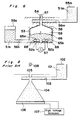
- FIG. 8 An ink jet recording apparatus of on-demand type capable of jetting a liquid inking medium under the influence of a pressure applied whenever the necessity arises is well known in the art, an example of which is shown in Fig. 8 in schematic partial sectional representation.
- the illustrated prior art ink jet recording apparatus comprises an ink tank 102 accommodating therein a liquid inking medium 101, a displacement amplifying chamber 104 fluid-coupled with the ink tank 101 through a supply passage 103, a jetting nozzle 105 communicated with the displacement amplifying chamber 104, and a piezoelectric element 106 electrically connected with a high voltage generator 107.
- the high voltage generator 107 applies an electric signal to the piezoelectric element 106 to cause the piezoelectric element 106 to deform mechanically in a direction inwardly and outwardly of the displacement amplifying chamber 104.
- the internal pressure of the displacement amplifying chamber 104 is increased with the liquid inking medium 101 consequently expelled outwardly from the jetting nozzle 105 to form ink droplets 108 which are then successively travelling towards an image receptor (not shown) such as, for example, a recording paper.
- an image receptor not shown
- This type of ink jet recording apparatus is disclosed in, for example, the Japanese Laid-open Patent Publication No. 48-9622, published in 1973.
- the prior art ink jet recording apparatus of the type utilizing the piezoelectric element has the following problems.
- the application of a high voltage of about two hundreds volts to the piezoelectric element results only in a mechanical deformation of the piezoelectric element within the range of several micrometers to several tens micrometers and, therefore, a pressure chamber of an increased volume such as shown in Fig. 8 is necessitated to allow the displacement to be concentrated towards the nozzle.
- a pressure chamber of an increased volume such as shown in Fig. 8 is necessitated to allow the displacement to be concentrated towards the nozzle.
- the piezoelectric element is expensive, it is also difficult to reduce the cost of a recording head.
- the prior art ink jet recording apparatus has such problems in the accomplishment of the multi-nozzle system and also in the reduction in both size and manufacturing cost of the ink recording apparatus.
- the present invention has been devised with the foregoing taken into consideration and is intended to provide an improved ink jet recording apparatus of a type capable of easily accommodating the multi-nozzle system and also capable of being manufactured in a compact size and at a reduced cost.
- the present invention provides an ink jet recording apparatus which comprises an decomposing chamber accommodating therein a liquid inking medium containing an electrolyte, a pair of electrodes disposed within the decomposing chamber, an ink supply means for supplying the liquid inking medium into the decomposing chamber, and a signal generating means for applying to the pair of the electrodes a signal necessary to electrolyze at least a portion of the electrolyte contained in the liquid inking medium.
- the liquid electrolyte contained in the liquid inking medium can be decomposed by the pair of the electrodes accompanied by the production of gaseous bodies.
- Forces resulting from expansion in volume of the respective gaseous bodies, or shock waves resulting from an discharge explosion of the gaseous bodies developed as a result of the electrolysis, are utilized to expel the liquid inking medium outwardly from the decomposing chamber in the form of ink droplets which subsequently travel towards an image receptor sheet to accomplish a recording.
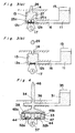
- the ink jet recording apparatus comprises a liquid inking medium 11 containing an liquid electrolyte and a coloring agent, a pair of electrodes 12a and 12b used to electrolyze the liquid electrolyte contained in the inking medium 11, an decomposing chamber 13 capable of accommodating the inking medium 11 and having an interior wall to which the pair of the electrodes 12a and 12b are disposed, a nozzle 14 from which the inking medium 11 can be expelled outwardly in the form of successively travelling ink droplets, an ink tank 15 for the storage therein of the liquid inking medium 11, an ink supply passage 16 through which the inking medium 11 within the ink tank 15 is supplied into the decomposing chamber 13 and then onto the nozzle 14, and a signal generator 17 for applying a signal voltage to the pair of the electrodes 12a and 12b.
- the signal generator 17 includes an pulse oscillator 20 capable of outputting a signal output voltage Vin, when a signal is inputted thereto through an input terminal In, and also capable of zeroing the output voltage (i.e., rendering the output voltage to be a zero volt) when an Off signal is inputted thereto, and a delay circuit 21 for delaying the generation of the output from the pulse oscillator 20 for a predetermined time indicated by Pw in Fig. 2(b).
- This signal generator 17 outputs the output of such a pattern as shown in Fig. 2(b), having a voltage Vin and a pulse width Pw for each cycle T thereof, which output is in turn applied between the electrodes 12a and 12b.
- the inking medium 11 is supplied from the ink tank 15 into the decomposing chamber 13 and then into the nozzle 14 through the ink supply passage 16. Subsequent application of the signal voltage from the signal generator 17 to the electrodes 12a and 12b results in electrolysis of that portion of the liquid electrolyte contained in the inking medium which is in contact with the electrodes 12a and 12b, producing gas bubbles 18a and 18b.
- the inking medium can be jetted outwardly from the nozzle 14 as indicated by 19 in Fig. 1.
- both of the decomposing chamber 13 and the nozzle 14 are filled with gas, both of the decomposing chamber 13 and the nozzle 14 are immediately replenished with the inking medium 11 then supplied from the ink tank 15 through the ink supply passage 16 to resume an initial condition, completing one cycle of jetting of an ink droplet. By repeating this cycle, the recording can be accomplished.
- Each of the electrodes 12a and 12b is made of material having a resistance to corrosion from the liquid electrolyte.
- nickel, platinum, gold, silver or graphite may be chosen as material for each electrodes 12a and 12b.
- the electrodes 12a and 12b may be made of different material chosen from this group.
- the liquid inking medium 11 contains the liquid electrolyte and the coloring agent.
- the coloring agent may be any dyestuff or pigments.
- the liquid inking medium 11 may contain one or more additives including a water-soluble resinous binder such as, for example, polyethylene glycol, polyvinyl alcohol or starch, and a surface active agent for assisting a dispersion of the dyestuffs or pigments and/or for assisting a surface tension.
- the liquid electrolyte employable in the practice of the present invention is a liquid medium containing a solvent and an electrolyte dissolved in the solvent with at least a portion thereof ionized.
- the solute include, for example, sodium hydroxide, potassium hydroxide, sulfuric acid and sodium chloride
- examples of the solvent include, for example, water and alcohols.
- the inking medium 11 may also contain any liquid medium other than the solvent, for example, aceton or methyl ethyl ketone.
- the inking medium 11 may be in the form of an emulsion of a kind wherein oily droplets containing the coloring agent and the binder are dispersed in the liquid electrolyte.
- the inking medium 11 is of a composition wherein the above described various compositions are preferably so combined that, during the electrolysis using the electrodes 12a and 12b, gases can be produced from the electrodes 12a and 12b to avoid any possible formation of deposits on the surface of each of the electrodes 12a and 12b.
- Material for the wall defining each of the nozzle 14, the ink supply passage 16 and the ink tank 15 should be of a type resistant to the attack from the inking medium 11 and includes, for example, ceramics such as, for example, quarts glass and alumina; metals such as, for example, brass and aluminum; curable resins such as, for example, epoxy resin; and thermoplastic resin such as, for example, acryl resin.
- Material for the wall defining the decomposing chamber 13 in which the electrodes 12a and 12b are disposed is one of the materials for the nozzle 14 and at least an interior wall of the decomposing chamber 13 is made of insulating material such as quartz glass, silicon oxide or resin.
- the ink jet recording apparatus was assembled for experimental purpose in the following manner.
- a pair of electrode patterns (spaced 30 ⁇ m from each other) were formed of nickel on a quartz glass plate, followed by placement of a dry film resist (manufactured by I.E. du Pont de Nemours & Company and sold under a tradename "Solder Mask"), having a perforation of 100 x 100 ⁇ m in size and a rectangular opening (60 ⁇ m in width and 500 ⁇ m in length) defined therein in communication with said perforation, over the quartz glass plate so as to surround the nickel electrodes.
- the assembly was subsequently radiated with ultraviolet rays of light to accomplish a primary curing.
- a nickel foil of 20 ⁇ m in thickness having a perforation of 50 ⁇ m in diameter formed thereon by the use of an etching technique was applied to the quartz glass plate with the perforation positioned above a point intermediate between the nickel electrodes, followed by the heating of the assembly at 150°C for 30 minutes to form both of the decomposing chamber 13 (100 x 100 ⁇ m in size and 20 ⁇ m in height) and the nozzle 14 (50 ⁇ m in diameter and 20 gm in length).
- the inking medium 11 used was of a composition comprising 20 parts by weight of water, 5 parts by weight of sodium hydroxide, 5 parts by weight of isopropyl alcohol and 0.5 parts by weight of black dyestuffs (direct dyestuffs identified by "Kayaset Black 008(N)".
- the inking medium 11 could be supplied by the effect of capillarity from the rectangular opening in the dry film resist.
- the signal supplied from the signal generator 17 was chosen to be a pulse of 50 Hz in frequency and 5 ms in width Pw, the inking medium 11 could be jetted at 60 volts in signal output voltage Vin to form a black-and-white recording on a high quality paper.
- the electrolysis of water to produce hydrogen and oxygen requires an application of a 2-volt voltage and, thus, the application of a relatively low voltage suffices to produce gaseous bodies.
- gases are produced immediately after consequent upon the application of the voltage charges have been moved on respective surfaces of the electrodes, a high response to the applied signal voltage can be appreciated.
- the disposition of the two electrodes is sufficient and, since the volumetric change (the change in volume incident to the transformation of the liquid phase to the gas phase) induced by the electrolysis is large, no displacement amplification such as used in the prior art recording apparatus is necessitated.
- the decomposing chamber may be small in size, the multi-nozzle system can readily be adopted, and reduction in size of the recording apparatus and also in manufacturing cost can readily be attained.
- Fig. 3 which pertains to a second preferred embodiment of the present invention
- the ink jet recording apparatus shown therein is substantially identical with that shown in and described with reference to Fig. 1, except that the signal output voltage Vin generated by the signal generator 17 used in the practice of the second preferred embodiment although similar in pattern to that shown in Fig. 2(b) is higher than that used in the first preferred embodiment so that the gaseous bodies produced within the decomposing chamber 13 as a result of the electrolysis can undergo a discharge explosion necessary to accomplish the jetting of the inking medium.
- the recording is carried out in the following manner.
- the inking medium 11 is supplied from the ink tank 15 into the decomposing chamber 13 and then into the nozzle 14 through the ink supply passage 16. Subsequent application of the signal voltage from the signal generator 17 to the electrodes 12a and 12b results in electrolysis of that portion of the liquid electrolyte contained in the inking medium which is in contact with the electrodes 12a and 12b, producing gas bubbles 25a and 25b.
- the inking medium can emerge outwardly from the nozzle 14 to form a pencil of ink as indicated by 26 in Fig. 3(a).
- the bubbles 25a and 25b are mixed together accompanied by a reduction in amount of the inking medium 11 which is in direct contact with the surfaces of the electrodes 12a and 12b. If at this time a voltage of a value enough to discharge remains applied to the electrodes 12a and 12b, a spark discharge indicated by 27 in Fig. 3(a) takes place in a mixed gas comprised of the bubbles 25a and 25b. As a result of the spark discharge, the mild gas of the bubbles 25a and 25b reacts explosively to return to the solvent. The explosion occurring during the reaction brings about shock waves by which the inking ,medium 11 can be expelled outwardly from the nozzle 14 to form an ink droplet 28, shown in Fig.
- both of the decomposing chamber 13 and the nozzle 14 are immediately replenished with the inking medium 11 then supplied from the ink tank 15 through the ink supply passage 16 to resume an initial condition, completing one cycle of jetting of an ink droplet. By repeating this cycle, the recording can be accomplished.
- the applied voltage required to accomplish the discharge explosion described above is low, for example, about 30 volts where the gaseous bodies so formed are spaced 10 ⁇ m from each other. Accordingly, where the electrodes are spaced a distance of 10 ⁇ m, the application of the voltage of about 30 volts to the liquid electrolyte can result in the formation of gases (hydrogen and oxygen) in the vicinity of each of the electrodes, which gases are subsequently mixed together to cover the spacing between the electrodes.
- gases hydrogen and oxygen
- the electrodes 12a and 12b are positioned close to each other with the distance therebetween so chosen as to be of a value enough to facilitate the discharge explosion.
- the applied voltage Vin supplied from the signal generator 17 was chosen to be of a value lower than 70 volts, no discharge was confirmed and the inking medium 11 expelled outwardly from the nozzle was pulsated at about 100 Hz. No pulsating discharge of the inking medium at 500 Hz was obtained. It appeared that, since the applied voltage was too low to effect the discharge, the inking medium was discharged by the action of gases developed as a result of the previously described electrolysis.
- the shock waves which are developed consequent upon discharge explosion of gases produced as a result of the electrolysis are utilized, the use of the decomposing chamber of relatively small size is sufficient and the multi-nozzle system can readily be adopted. Also, since the shock waves developed as a result of the explosion are utilized, the electrolysis need nob be effected until the whole interior of the decomposing chamber 13 is filled up with the gases produced as a result of the electrolysis and since a relatively small quantity of the gases is sufficient to expel the inking medium, the cycle T of the signal can be shortened as compared with the case in which only the electrolysis is relied upon, and therefore, a high speed recording can be accomplished.
- reference numeral 31 represents an inking medium containing an electrolyte and a coloring agent
- reference numerals 32a and 32b represent a pair of electrodes, respectively
- reference numeral 33 represents a decomposing chamber which can be filled up with the inking medium 31 and having an interior wall to which the electrodes 32a and 32b are attached
- reference numeral 34 represents a nozzle from which the inking medium 31 can be expelled outwardly to the atmosphere
- reference numeral 35 represents an ink tank accommodating the inking medium 31
- reference numeral 36 represents an ink supply passage through which the inking medium within the ink tank 35 can be supplied to the decomposing chamber 33
- reference numeral 37 represents a signal generator for applying a signal voltage to the electrodes 32a and 32b.
- the recording apparatus shown therein also comprises a filtering membrane 38 disposed within the decomposing chamber 33 so as to divide the interior of the decomposing chamber 33 into a nozzle room and an electrolyte room, said filtering membrane 33 being of a type capable of passing only the electrolyte, contained in the inking medium 31, therethrough into the electrolyte room.
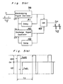
- FIG. 5(a) An essential portion of the signal generator 37 used in the practice of the third preferred embodiment of the present invention is shown in Fig. 5(a) in the form of a block circuit diagram, and the pattern of the output signal applied from the signal generator 37 to the electrodes 32a and 32b is shown in Fig. 5(b). As shown in Fig.
- the signal generator 37 includes an electrolyzing signal oscillator 39 capable of outputting an electrolyzing signal voltage V20, when an On signal is inputted to the input terminal In, and also of zeroing the output voltage when an Off signal is inputted thereto; a discharge signal oscillator 40 capable of outputting a discharge signal voltage V21, higher than the electrolyzing signal voltage V20 and opposite in polarity to that of the electrolyzing signal voltage V20, when an On signal is inputted thereto, and also of zeroing the output voltage when an Off signal is inputted thereto; a first delay circuit 41 operable to delay the output of the electrolyzing signal oscillator 39 for a predetermined time Pw20 to provide the Off signal to the electrolyzing signal oscillator 39 and also to provide the input to the discharge signal oscillator 40; a second delay circuit 42 operable to delay the output of the discharge signal oscillator 40 for a predetermined time Pw21 to provide the Off signal to the discharge signal oscillator 40; and an OR circuit 43 capable of outputting a composite of respective outputs
- the signal generator 37 shown in Fig. 5(a) can generate such a signal pattern as shown in Fig. 5(b) and applies, during each cycle T2, to the electrodes 32a and 32b the electrolysis signal voltage V20 having a pulse width Pw20 and, subsequently, the discharge signal voltage V21 of a polarity opposite to that of the electrolyzing signal voltage V20 and having a pulse width Pw21.
- the recording with the use of the recording apparatus according to the third preferred embodiment of the present invention takes in the following manner.
- the inking medium 31 is supplied from the ink tank 35 into the decomposing chamber 33 and then into the nozzle 34 through the ink supply passage 36.
- the electrolyte room of the decomposing chamber 33 is filled with a liquid medium 44 within the decomposing chamber 33, which medium 44 is mixed with at least the liquid electrolyte having passed through the filtering medium 38.
- the electrolyzing signal voltage V20 is applied at a pulse width Pw20 from the signal generator 37 to the electrodes 32a and 32b to cause the electrolyte, contained in the liquid medium 44 within the electrolyte room and contacting respective surfaces of the electrodes 32a and 32b, to undergo an electrolysis thereby to produce gas bubbles 45a and 45b on the respective surfaces of the electrodes 32a and 32b so that, by the effect of the volumetric expansion, the inking medium 34 can be discharged outwardly from the nozzle 34 to form an ink meniscus 46.
- the discharge signal voltage V21 opposite in polarity to that of the electrolyzing signal voltage V20 is applied to the same electrodes 32a and 32b and, therefore, a portion of the liquid electrolyte is further electrolyzed by the discharge signal voltage V21 wherefore mixed gases are developed within the respective gas bubbles 45a and 45b accompanied by a spark discharge 47 occurring in the vicinity of the respective electrode 32a and 32b.
- the inking medium 31 is expelled outwardly from the nozzle 34 in the form of an ink droplet (not shown). This ink droplet travels towards an image receptor (not shown) and subsequently deposits thereon to accomplish a recording.
- both of the decomposing chamber 33 and the nozzle 34 are immediately replenished with the inking medium 31 then supplied from the ink tank 35 through the ink supply passage 36 to resume an initial condition, completing one cycle of jetting of an ink droplet. By repeating this cycle, the recording can be accomplished.
- the foregoing cycle can be repeated by discharging the remaining gases together with the inking medium 31.
- composition of the inking medium 31, the material for the wall defining each of the decomposing chamber 33, the nozzle 34, the ink supply passage 36 and the ink tank 35 may be identical with those described in connection with the first preferred embodiment of the present invention.
- the filtering membrane 38 may be made of material of a kind capable of filtering at least the liquid electrolyte, contained in the inking medium 31, and the gases produced as a result of the electrolysis.
- the filtering membrane 38 may be made of material of microporous or mesh structure such as, for example, metal, ceramics or polymer, which is effective to remove particles contained in the inking medium 31.
- the inking medium 31 of a type in which pigments such as, for example, graphite or carbon, are dispersed in the liquid electrolyte is used in combination with the filtering membrane 38 in the form of a microporous polymer membrane of about 10 pm in thickness, the pigments do not pass through the filtering membrane 38 and the electrolyte room of the decomposing chamber 33 can almost be filled up with the liquid electrolyte.
- the recording apparatus makes use of the electrolysis and can be manufactured in a compact size at a reduced cost while accomplishing a high speed recording.
- the use of the filtering membrane 38 permits the electrolyte room of the decomposing chamber 33 to be filled with the liquid medium 44 within the decomposing chamber 33 containing the liquid electrolyte in a proportion higher than that in the inking medium 31, and therefore, the electrolysis will not be hampered which would otherwise occur in the presence of the coloring agent and the additives both contained in the inking medium 31 and separated by the filtering membrane 38, thereby accomplishing an efficient electrolysis.
- the lifetime of the recording apparatus can be advantageously increased as compared with that according to the first preferred embodiment of the present invention.
- the electrolysis signal and the discharge signal are opposite in polarity to each other, the electrolysis occurs somewhat before the discharge when the discharge voltage is applied and, therefore, the gases produced in the vicinity of the electrodes 32a and 32b can be rendered to be mixed gases. Accordingly, the spacing between the electrodes 32a and 32b need not be narrowed and, therefore, the recording apparatus can be easily assembled.
- the electrolysis signal and the discharge signal which are same in polarity may be applied between the electrodes in the case of the recording apparatus wherein the spacing between the electrodes is reduced such as shown in connection with the first preferred embodiment of the present invention.
- the recording apparatus according to the third preferred embodiment of the present invention can be used and operated in a manner similar to that according to the first preferred embodiment of the present invention wherein the gases developed as a result of the electrolysis are utilized to expel the inking medium outwardly from the nozzle.
- the recording apparatus according to the third preferred embodiment is used and operated in the manner similar to that according to the first preferred embodiment, a longer time is required to purge the gases filling up the nozzle 34 subsequent to the jetting of the inking medium 31 and then to fill the nozzle 34 with the inking medium 34, and therefore, the utilization of the discharge explosion is preferred in the recording apparatus according to the third preferred embodiment.
- the ink jet recording apparatus was assembled for experimental purpose in the following manner.
- a pair of electrode patterns (spaced 50 ⁇ m from each other) were formed of nickel on a quartz glass plate, followed by attachment of a polycarbonate membrane (used as the filtering membrane 38 and manufactured and sold by Nomura Micro-Science under a tradename "Nuclepore Micromembrane") having a thickness of 10 ⁇ m, so as to surround the electrodes and then followed by the attachment of a dry film resist (manufactured and sold by I.E.
- du Pont de Nemours & Company under a tradename "Solder Mask” having a perforation of 100 x 100 ⁇ m in size and a rectangular opening (60 ⁇ m in width and 500 ⁇ m in length) defined therein in communication with said perforation, over the quartz glass plate so as to cover the filtering membrane 38.
- the assembly was subsequently radiated with ultraviolet rays of light to accomplish a primary curing.
- a nickel foil of 20 ⁇ m in thickness having a through-hole of 50 ⁇ m in diameter formed therein by the use of an etching technique was applied to the quartz glass plate and, thereafter, the assembly was heated at 110°C for 50 minutes to form both of the decomposing chamber 33, 100 x 100 ⁇ m in size and 20 ⁇ m in height, and the nozzle, 50 ⁇ m in diameter and 20 ⁇ m in length.
- the bonding takes place at the dry film and, therefore, no contact occurred substantially between the filtering membrane 38 and the electrodes. In other words, only the liquid medium having passed through the filtering membrane 38 can contact the electrodes 32a and 32b.
- the inking medium 31 used was of a composition comprising 20 parts by weight of water, 5 parts by weight of sodium hydroxide, 5 parts by weight of isopropyl alcohol and 5 parts by weight of graphite. Thereafter, while the recording apparatus as a whole is reduced in pressure with the aid of a vacuum pump, the inking medium 31 was filled in the recording apparatus by connecting the inking medium 31 with an opening of the ink supply passage 36.
- the signal generator 37 is driven by a pulse width (500 Hz, Pw20: 0.5 ms, Pw21: 0.1 ms)
- a black-and-white recording on a high quality paper could be achieved with the electrolyzing signal voltage V20 being 30 volts and with the discharge signal voltage V21 being 100 volts.
- the application of the voltage could be minimized as compared with that in the previous embodiment and therefore a low energy consumption could be accomplished.
- reference numeral Slm represents an inking medium containing a coloring agent
- reference numeral 51n represents a liquid electrolyte capable of being electrolyzed
- reference numerals 52a and 52b represent a pair of electrodes operable to electrolyze the electrolyte 51n
- reference numeral 53 represents a decomposing chamber capable of being filled with the inking medium 51 and having an interior wall to which the electrodes 52a and 52b are attached
- reference numeral 54 represents a nozzle from which the inking medium 51 can be expelled outwardly to the atmosphere
- reference numeral 55m represents an ink tank accommodating therein the inking medium slm
- reference numeral 55n represents an electrolyte tank accommodating therein the liquid electrolyte
- reference numeral 56m represents an ink supply passage through which at least the nozzle 54 can be filled with the inking medium 51m from the ink tank 55m
- reference numeral 56n represents an ink supply passage through which at least the nozzle 54 can be filled with the inking medium 51m from the
- a portion of the wall defining the decomposing chamber 53 is employed in the form of a water-repellent wall 58 and a gaseous medium 59 is employed to separate the inking medium 51m and the electrolyte 51n from each other thereby to avoid any possible contact therebetween within the decomposing chamber 53.
- the signal generator 57 includes an electrolyzing signal oscillator 60 capable of rendering an output voltage to be zero volt upon receipt of an Off signal after a voltage V30 and a voltage opposite in polarity to the voltage V30, each being of a pulse width Pw30 as shown in Fig.
- a discharge signal oscillator 61 capable of rendering an output voltage to be zero upon receipt of an Off signal after a voltage V31 has been outputted in response to the inputting of an On signal
- a counter 62 for providing the Off signal and the On signal to the electrolyzing signal oscillator 60 and the discharge signal oscillator 61, respectively, when the number of changes of the output voltage from the electrolyzing signal oscillator 60 counted thereby attains a predetermined number
- a delay circuit 63 operable to delay the output of the discharge signal oscillator 61 for a predetermined time Pw31 to provide the Off signal to the discharge signal oscillator 61
- an OR circuit 64 capable of outputting a composite of respective outputs from the signal oscillators 60 and 61.
- the signal generator 57 shown in Fig. 7(a) can generate such a signal pattern as shown in Fig. 7(b) and applies, during each cycle T3, to the electrodes 52a and 52b the electrolysis signal voltages V30 of opposite polarities each having a pulse width Pw30 and, subsequently, the discharge signal voltage V31 having a pulse width Pw31.
- the recording with the use of the recording apparatus according to the fourth preferred embodiment of the present invention takes place in the following manner.
- the inking medium 51m is filled in the nozzle 54 from the ink tank 55m through the ink supply passage 56m and, at the same time, at least the respective surfaces of the electrodes 52a and 52b are filled with the electrolyte 51n.
- the nozzle 54 need not be completely filled with the inking medium 51m.
- the signal voltage is subsequently applied from the signal generator 57 to the electrodes 52a and 52b to effect the electrolysis during which the electrolyte 51n contacting the electrodes 52a and 52b are electrolyzed to produce bubbles 65a and 65b on the respective surfaces of the electrodes 52a and 52b.
- the interface 66 of the electrolyte is convexed so as to protrude towards the nozzle 54 with an outwardly protruding ink meniscus 67 consequently formed in the nozzle 54.
- the electrolyzing signal voltage V30 applied comprises two voltage components of opposite polarities, a mixed gas exists within each of the bubbles 65a and 65b. Accordingly, the subsequent application of the discharge signal voltage V31 to the electrodes 52a and 52b results in a spark discharge 68 occurring in the vicinity of each of the electrodes 52a and 52b.
- the inking medium 51m can be discharged outwardly from the nozzle 54 and grows into an ink droplet (not shown) then travelling towards an image receptor.
- the recording can be accomplished.
- the inking medium 51m is supplied through the ink supply passage 56m towards the nozzle 54.
- the bubbles 65a and 65b when exploded as a result of the spark discharge 68, resume a liquid phase, a portion thereof is discharged to the outside together with the inking medium and, therefore, is consumed.
- the electrolyte 51n is supplied through the electrolyte supply passage 56n to resume an initial condition, thereby completing each cycle. By repeating this cycle, the recording can be accomplished.
- Material for the wall defining each of the decomposing chamber 53, the nozzle 54, the ink supply passage 56m and the ink tank 55m may be identical with, for example, that described in connection with the first preferred embodiment of the present invention.
- the electrolyte supply passage 56n and the electrolyte tank 55n may be made of the same material as that used for, for example, the ink supply passage 56m and the ink tank 55m.
- the inking medium 51m utilizable in the practice of the present invention may be of a kind capable of being electrolyzed, that is, containing no electrolyte, either water-based or oil-oil based.
- the water-repellent wall 58 is formed of material of a type capable of repelling any one of the inking medium 51m and the liquid electrolyte 51n.
- silicone or fluoroplastics may be employed for lining an interior wall of the decomposing chamber 53 to form the water-repellent wall 58.
- the recording apparatus according to the fourth preferred embodiment of the present invention makes use of the electrolysis and can be manufactured in a compact size at a reduced cost while accomplishing a high speed recording.
- the recording apparatus according to the fourth embodiment of the present invention furthermore has the following additional advantages.
- One of the additional advantages is that, since the inking medium 51m need not contain the electrolyte, the freedom of choice of inking medium is relatively large.
- Another one of the additional advantages is that, since only the liquid electrolyte 51n contacts the respective surfaces of the electrodes 52a and 52b and there is no impurity and nothing which would otherwise deposit on the surfaces of the electrodes, the electrolysis can take place efficiently with an increase in sensitivity.
- the inking medium 51m can be expelled by the sole action of the gases generated as a result of the electrolysis as is the case with that in the first preferred embodiment of the present invention.
- a longer time is required to purge the gases filling up the nozzle 54 subsequent to the jetting of the inking medium 51m and then to fill the nozzle 54 with the inking medium 51m, and therefore, the utilization of the discharge explosion is preferred in the recording apparatus according to the fourth preferred embodiment.
- the ink jet recording apparatus was assembled for experimental purpose in the following manner. After respective portions of a glass substrate which eventually form the electrolyte supply passage 56n and the decomposing chamber 53 have been etched to represent recesses, a pair of electrode patterns (spaced 50 ⁇ m from each other) were formed in those recesses by vapor-depositing nickel with the use of an etching technique. Then, after grooves corresponding respectively to respective surfaces of the electrodes and the electrolyte supply passage 56 have been covered by polyethylene glycol (manufactured and sold by Dai-ichi Kogyo Seiyaku Co., Ltd.
- PEG #20000 the remaining recesses were applied with fluororesin (manufactured and sold by Sumitomo Chemical Co., Ltd. under a tradename “Sumiflunon FP91A) and were then dried. Thereafter, the PEG was flushed with water, followed by the placement of a dry film resist (manufactured and sold by I.E. du Pont de Nemours & Company under the tradename "Solder Mask”) having a round through-hole of 80 ⁇ m in diameter and a rectangular opening (which eventually form the ink supply passage 56m) defined therein in communication with the round through-hole, which was subsequently radiated with the ultraviolet rays of light for a primary curing.
- a dry film resist manufactured and sold by I.E. du Pont de Nemours & Company under the tradename "Solder Mask” having a round through-hole of 80 ⁇ m in diameter and a rectangular opening (which eventually form the ink supply passage 56m) defined therein in
- the inking medium 51m used was a commercially available black ink for use with an airbrush made and sold by Holbein Works Ltd., while the liquid electrolyte 51n was of a composition containing 20 parts by weight of water and 5 parts by weight of sodium hydroxide.
- the inking medium used is of a type capable of exhibiting a waterproof when dried. Thereafter, while the recording apparatus was reduced in pressure with the aid of a vacuum pump, the electrolyte supply passage 56n is contacted with the electrolyte 51n to fill the recording apparatus with the electrolyte 51n.
- the inking medium 51m was discharged some times to render the recording apparatus to assume such a condition as shown in Fig. 6.
- the signal generator 57 is driven by a pulse width (500 Hz, Pw30: 0.2 ms, Pw31: 0.1 ms)
- a black-and-white recording on a high quality paper could be achieved with the electrolyzing signal voltage V30 being 30 volts and with the discharge signal voltage V31 being 100 volts.
- the use has been made of the gases as a medium operable to transmit a pressure, produced upon the generation of the gases, to the inking medium.
- the use may be made of a liquid medium insoluble in the liquid electrolyte and the inking medium, or a solid matter having a rubber elasticity. In such case, no electrolyte will be discharged together with the inking medium when the discharge explosion takes place and, therefore, the electrolyte 51n need not be supplemented, making it possible to render the recording apparatus to be simple in structure.
- the electrolyzing signal used may comprise voltages of the same or opposite polarities or of different pulse width.
- the electrolyzing signal has been described as comprising a single-time inverted signal, it may comprise a combination of inverted signals.
- the discharge signal may be applied a predetermined time subsequent to the application of the electrolyzing signal provided that the both are generated within the same cycle T2 or T3.
- the signal generator may not be always limited to the design shown and described, but may be of any suitable design provided that the previously discussed signal voltage or voltages can be generated therefrom.
- the recording apparatus shown in Fig. 3 can make use of the signal generator shown in and described with reference to any one of Figs. 5 and 7 and, in a similar way, some of the component parts, such as, for example, the decomposing chamber and/or the signal generator, which have been described and shown in connection with one preferred embodiment of the present invention can be combined with those which have been described and shown in connection with another preferred embodiment of the present invention.
Landscapes
- Particle Formation And Scattering Control In Inkjet Printers (AREA)
- Ink Jet (AREA)
Applications Claiming Priority (4)
| Application Number | Priority Date | Filing Date | Title |
|---|---|---|---|
| JP1241251A JPH03104650A (ja) | 1989-09-18 | 1989-09-18 | 記録装置 |
| JP241251/89 | 1989-09-18 | ||
| JP243727/89 | 1989-09-19 | ||
| JP1243727A JPH03104651A (ja) | 1989-09-19 | 1989-09-19 | 記録装置 |
Publications (3)
| Publication Number | Publication Date |
|---|---|
| EP0418659A2 true EP0418659A2 (fr) | 1991-03-27 |
| EP0418659A3 EP0418659A3 (en) | 1992-09-23 |
| EP0418659B1 EP0418659B1 (fr) | 1997-01-08 |
Family
ID=26535164
Family Applications (1)
| Application Number | Title | Priority Date | Filing Date |
|---|---|---|---|
| EP90117138A Expired - Lifetime EP0418659B1 (fr) | 1989-09-18 | 1990-09-06 | Dispositif d'enregistrement à jet d'encre |
Country Status (3)
| Country | Link |
|---|---|
| US (2) | US5072242A (fr) |
| EP (1) | EP0418659B1 (fr) |
| DE (1) | DE69029632T2 (fr) |
Cited By (3)
| Publication number | Priority date | Publication date | Assignee | Title |
|---|---|---|---|---|
| EP0783965A3 (fr) * | 1995-08-22 | 1997-09-03 | Nec Corp | Appareil de projection de gouttes de fluide et méthode de projection de gouttes de fluide |
| EP0820868A3 (fr) * | 1996-07-24 | 1998-10-28 | Samsung Electronics Co., Ltd. | Dispositif et méthode d'injection d'encre dans une imprimante à jet d'encre |
| US6450615B2 (en) | 1997-02-19 | 2002-09-17 | Nec Corporation | Ink jet printing apparatus and method using a pressure generating device to induce surface waves in an ink meniscus |
Families Citing this family (9)
| Publication number | Priority date | Publication date | Assignee | Title |
|---|---|---|---|---|
| US5870124A (en) * | 1995-04-12 | 1999-02-09 | Eastman Kodak Company | Pressurizable liquid ink cartridge for coincident forces printers |
| JP2004001490A (ja) * | 2002-04-23 | 2004-01-08 | Canon Inc | インクジェットヘッド |
| JP2004001488A (ja) * | 2002-04-23 | 2004-01-08 | Canon Inc | インクジェットヘッド |
| JP3950730B2 (ja) * | 2002-04-23 | 2007-08-01 | キヤノン株式会社 | インクジェット記録ヘッドおよびインク吐出方法 |
| KR20050060288A (ko) * | 2003-12-16 | 2005-06-22 | 삼성전자주식회사 | 잉크젯 프린트헤드 |
| JP3965586B2 (ja) * | 2004-03-31 | 2007-08-29 | 富士フイルム株式会社 | 液滴吐出ヘッド及び画像形成装置 |
| WO2008112612A1 (fr) * | 2007-03-15 | 2008-09-18 | Albany International Corp. | Bande aspirante pour tabac |
| US8517487B2 (en) * | 2010-06-22 | 2013-08-27 | Conexant Systems, Inc. | Systems and methods for dielectric heating of ink in inkjet printers |
| US11440321B2 (en) * | 2019-12-12 | 2022-09-13 | Xerox Corporation | Gas expansion material jetting actuator |
Family Cites Families (8)
| Publication number | Priority date | Publication date | Assignee | Title |
|---|---|---|---|---|
| SE349676B (fr) * | 1971-01-11 | 1972-10-02 | N Stemme | |
| US3949410A (en) * | 1975-01-23 | 1976-04-06 | International Business Machines Corporation | Jet nozzle structure for electrohydrodynamic droplet formation and ink jet printing system therewith |
| DE2507969C3 (de) * | 1975-02-25 | 1980-09-25 | Olympia Werke Ag, 2940 Wilhelmshaven | Druckkopf für ein Tintenspritz-Schreibwerk |
| DE2624778C3 (de) * | 1975-06-03 | 1980-07-03 | Ricoh Co., Ltd., Tokio | Tintenausstoßkopf |
| US4275290A (en) * | 1978-05-08 | 1981-06-23 | Northern Telecom Limited | Thermally activated liquid ink printing |
| IT1195810B (it) * | 1981-10-05 | 1988-10-27 | Olivetti & Co Spa | Dispositivo di scrittura a getto selettivo di inchiostro relativo in choistro e processo di preparazione dell inchiotro |
| CH649040A5 (fr) * | 1982-10-08 | 1985-04-30 | Battelle Memorial Institute | Dispositif pour projeter des gouttelettes d'un liquide electriquement conducteur. |
| JPS59165662A (ja) * | 1983-03-10 | 1984-09-18 | Fuji Xerox Co Ltd | インクジエツト噴射装置 |
-
1990
- 1990-09-06 DE DE69029632T patent/DE69029632T2/de not_active Expired - Fee Related
- 1990-09-06 EP EP90117138A patent/EP0418659B1/fr not_active Expired - Lifetime
- 1990-09-13 US US07/581,754 patent/US5072242A/en not_active Expired - Fee Related
-
1991
- 1991-06-12 US US07/713,833 patent/US5130722A/en not_active Expired - Lifetime
Cited By (5)
| Publication number | Priority date | Publication date | Assignee | Title |
|---|---|---|---|---|
| EP0783965A3 (fr) * | 1995-08-22 | 1997-09-03 | Nec Corp | Appareil de projection de gouttes de fluide et méthode de projection de gouttes de fluide |
| US6328421B1 (en) | 1995-08-22 | 2001-12-11 | Nec Corporation | Fluid drop projecting head using taper-shaped chamber for generating a converging surface wave |
| CN1093792C (zh) * | 1995-08-22 | 2002-11-06 | 日本电气株式会社 | 液滴喷射装置和液滴喷射方法 |
| EP0820868A3 (fr) * | 1996-07-24 | 1998-10-28 | Samsung Electronics Co., Ltd. | Dispositif et méthode d'injection d'encre dans une imprimante à jet d'encre |
| US6450615B2 (en) | 1997-02-19 | 2002-09-17 | Nec Corporation | Ink jet printing apparatus and method using a pressure generating device to induce surface waves in an ink meniscus |
Also Published As
| Publication number | Publication date |
|---|---|
| DE69029632D1 (de) | 1997-02-20 |
| EP0418659A3 (en) | 1992-09-23 |
| US5072242A (en) | 1991-12-10 |
| EP0418659B1 (fr) | 1997-01-08 |
| DE69029632T2 (de) | 1997-05-22 |
| US5130722A (en) | 1992-07-14 |
Similar Documents
| Publication | Publication Date | Title |
|---|---|---|
| EP0418659B1 (fr) | Dispositif d'enregistrement à jet d'encre | |
| US4005435A (en) | Liquid jet droplet generator | |
| GB2166087A (en) | Liquid jet recording apparatus | |
| US4584590A (en) | Shear mode transducer for drop-on-demand liquid ejector | |
| EP2253473A1 (fr) | Module piézoélectrique à jet d'encre | |
| EP0888888A3 (fr) | Dispositif d'impression à jet d'encre actionné magnétiquement | |
| US20010015001A1 (en) | Ink-jet recording head, ink-jet recording apparatus using the same, and method for producing ink-jet recording head | |
| JPS555874A (en) | Ink collecting device in jet printer | |
| CN101982314A (zh) | 液体喷射装置 | |
| US4231046A (en) | Ink issuance orifice protection in an ink jet system printer | |
| JP2006509659A (ja) | ナノ構造物に基づく微細流体ポンプ装置及び方法 | |
| KR100906446B1 (ko) | 수소발생장치 제조방법 및 그것을 이용한 수소발생장치 | |
| EP0355862B1 (fr) | Imprimante à jet d'encre | |
| CN211918093U (zh) | 一种数字印刷喷墨控制系统 | |
| JPH03104651A (ja) | 記録装置 | |
| KR100863725B1 (ko) | 수소 발생 장치 및 연료전지 발전 시스템 | |
| JPH1110874A (ja) | 紫外線硬化型インク用のインクジェット式記録ヘッド | |
| Kretschmer et al. | A drop-on-demand inkjet printhead for a wide range of applications | |
| US6309043B1 (en) | Device using the action of a gas for controlling the movement of a fluid | |
| RU2832960C1 (ru) | Электрохимический актюатор | |
| JPH0117861B2 (fr) | ||
| JPH03104650A (ja) | 記録装置 | |
| JPH0557891A (ja) | インクジエツトプリントヘツド | |
| JP6631734B2 (ja) | 液体噴射ヘッド及び液体噴射装置 | |
| JP3127564B2 (ja) | インクジェットヘッド及びインクジェットヘッドの製造方法 |
Legal Events
| Date | Code | Title | Description |
|---|---|---|---|
| PUAI | Public reference made under article 153(3) epc to a published international application that has entered the european phase |
Free format text: ORIGINAL CODE: 0009012 |
|
| 17P | Request for examination filed |
Effective date: 19900906 |
|
| AK | Designated contracting states |
Kind code of ref document: A2 Designated state(s): DE FR GB |
|
| PUAL | Search report despatched |
Free format text: ORIGINAL CODE: 0009013 |
|
| RHK1 | Main classification (correction) |
Ipc: B41J 2/06 |
|
| AK | Designated contracting states |
Kind code of ref document: A3 Designated state(s): DE FR GB |
|
| 17Q | First examination report despatched |
Effective date: 19940801 |
|
| GRAH | Despatch of communication of intention to grant a patent |
Free format text: ORIGINAL CODE: EPIDOS IGRA |
|
| GRAH | Despatch of communication of intention to grant a patent |
Free format text: ORIGINAL CODE: EPIDOS IGRA |
|
| GRAH | Despatch of communication of intention to grant a patent |
Free format text: ORIGINAL CODE: EPIDOS IGRA |
|
| GRAH | Despatch of communication of intention to grant a patent |
Free format text: ORIGINAL CODE: EPIDOS IGRA |
|
| GRAA | (expected) grant |
Free format text: ORIGINAL CODE: 0009210 |
|
| AK | Designated contracting states |
Kind code of ref document: B1 Designated state(s): DE FR GB |
|
| REF | Corresponds to: |
Ref document number: 69029632 Country of ref document: DE Date of ref document: 19970220 |
|
| ET | Fr: translation filed | ||
| PLBE | No opposition filed within time limit |
Free format text: ORIGINAL CODE: 0009261 |
|
| STAA | Information on the status of an ep patent application or granted ep patent |
Free format text: STATUS: NO OPPOSITION FILED WITHIN TIME LIMIT |
|
| 26N | No opposition filed | ||
| PGFP | Annual fee paid to national office [announced via postgrant information from national office to epo] |
Ref country code: DE Payment date: 20000828 Year of fee payment: 11 |
|
| PGFP | Annual fee paid to national office [announced via postgrant information from national office to epo] |
Ref country code: GB Payment date: 20000906 Year of fee payment: 11 |
|
| PGFP | Annual fee paid to national office [announced via postgrant information from national office to epo] |
Ref country code: FR Payment date: 20000912 Year of fee payment: 11 |
|
| PG25 | Lapsed in a contracting state [announced via postgrant information from national office to epo] |
Ref country code: GB Free format text: LAPSE BECAUSE OF NON-PAYMENT OF DUE FEES Effective date: 20010906 |
|
| PG25 | Lapsed in a contracting state [announced via postgrant information from national office to epo] |
Ref country code: DE Free format text: LAPSE BECAUSE OF NON-PAYMENT OF DUE FEES Effective date: 20020501 |
|
| PG25 | Lapsed in a contracting state [announced via postgrant information from national office to epo] |
Ref country code: FR Free format text: LAPSE BECAUSE OF NON-PAYMENT OF DUE FEES Effective date: 20020531 |
|
| REG | Reference to a national code |
Ref country code: FR Ref legal event code: ST |