EP0418675A2 - Procédé et appareil pour la production d'images par échos multiples de résonance magnétique nucléaire - Google Patents
Procédé et appareil pour la production d'images par échos multiples de résonance magnétique nucléaire Download PDFInfo
- Publication number
- EP0418675A2 EP0418675A2 EP90117312A EP90117312A EP0418675A2 EP 0418675 A2 EP0418675 A2 EP 0418675A2 EP 90117312 A EP90117312 A EP 90117312A EP 90117312 A EP90117312 A EP 90117312A EP 0418675 A2 EP0418675 A2 EP 0418675A2
- Authority
- EP
- European Patent Office
- Prior art keywords
- gradient field
- pulse
- pulses
- slice
- echo
- Prior art date
- Legal status (The legal status is an assumption and is not a legal conclusion. Google has not performed a legal analysis and makes no representation as to the accuracy of the status listed.)
- Withdrawn
Links
- 238000005481 NMR spectroscopy Methods 0.000 title claims abstract description 22
- 238000003384 imaging method Methods 0.000 title claims abstract description 21
- 230000005415 magnetization Effects 0.000 claims abstract description 10
- 238000005259 measurement Methods 0.000 claims description 24
- 238000005070 sampling Methods 0.000 claims description 12
- 230000015572 biosynthetic process Effects 0.000 claims description 5
- 238000002592 echocardiography Methods 0.000 claims description 4
- 230000003068 static effect Effects 0.000 claims description 4
- 238000009826 distribution Methods 0.000 claims description 3
- 238000000034 method Methods 0.000 description 9
- 238000010586 diagram Methods 0.000 description 5
- 238000010276 construction Methods 0.000 description 3
- 230000005284 excitation Effects 0.000 description 3
- 230000008030 elimination Effects 0.000 description 2
- 238000003379 elimination reaction Methods 0.000 description 2
- 239000011159 matrix material Substances 0.000 description 2
- 239000007787 solid Substances 0.000 description 2
- 230000003247 decreasing effect Effects 0.000 description 1
- 229940079593 drug Drugs 0.000 description 1
- 239000003814 drug Substances 0.000 description 1
- 239000000543 intermediate Substances 0.000 description 1
Images
Classifications
-
- G—PHYSICS
- G01—MEASURING; TESTING
- G01R—MEASURING ELECTRIC VARIABLES; MEASURING MAGNETIC VARIABLES
- G01R33/00—Arrangements or instruments for measuring magnetic variables
- G01R33/20—Arrangements or instruments for measuring magnetic variables involving magnetic resonance
- G01R33/44—Arrangements or instruments for measuring magnetic variables involving magnetic resonance using nuclear magnetic resonance [NMR]
- G01R33/48—NMR imaging systems
- G01R33/54—Signal processing systems, e.g. using pulse sequences ; Generation or control of pulse sequences; Operator console
- G01R33/56—Image enhancement or correction, e.g. subtraction or averaging techniques, e.g. improvement of signal-to-noise ratio and resolution
- G01R33/565—Correction of image distortions, e.g. due to magnetic field inhomogeneities
- G01R33/56554—Correction of image distortions, e.g. due to magnetic field inhomogeneities caused by acquiring plural, differently encoded echo signals after one RF excitation, e.g. correction for readout gradients of alternating polarity in EPI
Definitions
- the present invention relates to multi-echo imaging method and apparatus utilizing nuclear magnetic resonance (hereinafter simply referred to as "NHR”) and more particularly to imaging method and apparatus capable of making correcter an image obtained in respect of spin-spin relaxation time T2.
- NHR nuclear magnetic resonance
- the multi-echo imaging method is described in, for example, "Magnetic Resonance in Medicine 3, pp 397-417 (1986)".
- the components M + and M o develop because the 180° RF pulse is not generated correctly and the magnetization vector M is not rotated through exact 180° (see USP 4,484,138).
- M o is directed in the same direction as that of the static magnetic field and is therefore not detected as an echo signal representative of T2.
- the component M + forms an artifact.
- the component M + leading to the artifact can be dephased effectively by applying pulses of additional magnetic field gradient before and after the 180° RF pulse.
- the additional pulse is called a crusher pulse.
- the artifact can be cancelled out by the additional pulses.
- an image is formed by putting together a plurality of echoes, that is, by applying the 180° RF pulse a plurality of times, the resulting image becomes incorrect. This is because the echo signals sampled for formation of the image contain error signals.
- an object of the present invention is to eliminate an artifical signal and an error signal from an echo signal to be sampled by dephasing a component causing an artifact (artifact component) as well as the error component, thereby making correct an image obtained when multi-echo imaging.
- the artifact component and error component can be dephased.
- combinations of magnitudes and widths of the gradient field pulses associated with the respective inversion pulses are selected in such a manner that dephasing of the artifact component and the error component can be maximized for elimination of these components.
- the multi-slice method in which measurement wait time is utilized to image another slice plane it is necessary to use a band-limited RF pulse (selective pulse) as the inversion pulse.
- the slice pitch is made to be greater than the thickness of the slice plane, wherein the slice thickness of the inversion pulse is set to be larger than the slice thickness of the exciting pulse and besides equal to or smaller than the slice pitch. In this manner, the waveform of the inversion pulse can be optimized for suppressing the error component to a minimum.
- the magnitudes and widths of the gradient field pulses in the three directions of slice direction, readout direction and encoding direction may be multiplied with a suitable matrix of rotation to obtain magnitides and widths of a new gradient field by which an image corresponding to a slice plane inclined in a desired direction can be obtained.
- the phase of a nuclear spin caused by an exciting pulse (90° RF pulse) Pe is inverted by inversion pulses (180° RF pulses) P1, P2, ... Pn ....
- inversion pulses 180° RF pulses
- a component M + not rotated and a component M o in the longitudinal magnetization direction are caused concomitantly.
- the component M - rotated at that time considers a gradient field subsequently applied as a negative quantity and is susceptive thereto.
- the component M + not rotated considers the gradient field as a positive quantity and is susceptive thereto but the component M o in the longitudinal magnetization direction is insusceptive to the gradient field.
- this echo signal contains a normal signal, an artifact signal and an error signal.
- this component M n has been affected by additional gradient field pulses applied in association with 1st to n-th echo signals.
- additional gradient field pulses are applied in three directions which are orthogonal to each other as shown in Fig. 2, the component M n is affected by gradient field pulses in the three directions. Accordingly, the respective gradient field pulses have the influence upon the component M n represented by a function Fn (S, R, E).
- variables S, R and E designate the total application amounts of the individual gradient field pulses in the slice selection, readout and encoding directions, respectively, and are indicated as follows: where W1, W2 ... Wn are quantities each of which can take a value of -1, 0 or +1 and are determined by the influence which the individual gradient field pulses have upon the component M n of magnetization vector at the inversion pulse Pn.
- W1, W2 ... Wn are quantities each of which can take a value of -1, 0 or +1 and are determined by the influence which the individual gradient field pulses have upon the component M n of magnetization vector at the inversion pulse Pn.
- W1, W2 ... Wn are quantities each of which can take a value of -1, 0 or +1 and are determined by the influence which the individual gradient field pulses have upon the component M n of magnetization vector at the inversion pulse Pn.
- the variables S, R and E of the function Fn are so set that both the artifact and error components can be dephased.
- the magnitudes (the products of intensity and time) of the gradient field pulses applied before and after each inversion pulse are so adjusted as to dephase all the artifact and error components.
- the study conducted by the present inventors showed that the gradient field pulses in at least two directions have to be adjusted in order to execute the aforementioned dephasing. And, the total application amount of each gradient field pulse must be sufficiently larger than zero in absolute value because the magnetization vector component M n can be dephased by the magnitude of the absolute value.
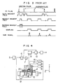
- Fig. 4 shows the construction of an imaging apparatus used for implementation of embodiments of the invention.
- a controller 5 delivers various instructions to units at predetermined timings.
- the output signal of an RF pulse generator 6 is amplified by an amplifier 7 and used to excite an RF coil 8.
- a signal component detected by the RF coil 8 is amplified by an amplifier 9, detected by a detector 10 and finally converted into an image by a signal processor 11.
- Gradient magnetic fields in Z, X and Y directions, orthogonal to each other, are respectively generated by gradient magnetic field coils 12, 13 and 14 which are driven by amplifiers 15, 16 and 17, respectively.
- a static magnetic field is generated by a coil 18 which is driven by a power supply 19.
- the coil 14 has the same construction as that of the coil 13 and is rotated about Z axis by 90 degrees relative to the coil 13.
- a human body 20 standing for an object to be examined is placed on a bed 21 which in turn is movable on a support 22.
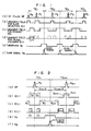
- Figs. 1 and 2 show general forms of measurement sequence according to embodiments to be described later individually. Essentially, each embodiment is based on the two-dimensional Fourier transform method (2DFT method) utilizing phase encoding. Obviously, the present invention may be applied to the three-dimensional Fourier transform method.
- 2DFT method two-dimensional Fourier transform method
- an RF pulse RF generated from the coil 8 is illustrated at section (a), a gradient field for slice selection and following additional pulses generated from any one of the gradient field coils 12, 13 and 14, that is, a waveform S(t) of a gradient field in a direction of slice selection is illustrated at (b), a waveform R(t) of a gradient field for readout and following gradient fields in a direction of readout generated from any one of the remaining gradient field coils 12, 13 and 14 is illustrated at (c), and a waveform E(t) of a gradient field for phase encoding (a gradient field in a direction of encoding) generated from the remainder of gradient field coil is illustrated at (d).
- Which one of the gradient field coils 12, 13 and 14 is used to generate the respective gradient fields shown at (b), (c) and (d) in Fig. 1 is selected depending on which direction a slice is imaged in.
- an inversion pulse P2 is applied at an intermediate time point of this period so that the peak of a second echo may appear at the end of this period.
- inversion pulses P3, ..., Pk are applied sequentially so that peaks of echoes may appear at the end of individual periods TE3, ..., TEk.
- a band-limited RF pulse selective pulse is used as the inversion pulse and applied simultaneously with the application of each gradient field for slice selection.
- a series of sequence described as above is repeated at the rate of the amplitude of the prepared gradient field for phase encoding.
- the two-dimensional Fourier transform having variables of two directions i.e., repetition direction and time lapse direction for measurement of each echo, a spin distribution can be obtained and by comparing images originating from the 1st to k-th echoes, information concerning spin-spin relaxation can be obtained.
- Fig. 2 Exaggeratedly illustrated in Fig. 2 is a portion around the n-th echo in the sequence of Fig. 1, that is, a portion covering the n-th period TEn and the (n+1)th period TEn+1. More particularly, the RF pulse is illustrated at (a) in Fig. 2, the waveform of the gradient field for slice selection is illustrated at (b), the waveform of the gradient field for readout is at (c), the waveform of gradient field for phase encoding is at (d), the signal sampling period is at (e) and the NMR signal is at (f).
- the product of intensity and time (time integral of intensity) of the gradient field for slice selection remains unchanged before and after the inversion pulse and the product of intensity and time of the gradient field for readout also remains unchanged around the inversion pulse.
- the product of intensity and time of the gradient field for slice selection before and after the inversion pulse Pn is designated by Sn and that of the gradient field for readout around that inversion pulse is designated by Rn.
- gradient field pulses in the same direction as that of the gradient field for phase encoding are applied before and after the inversion pulse.
- the product of intensity and time of this pulse is represented by En.
- sampling is carried out till the fourth echo and values of the products of intensity and time Sn, Rn and En of the respective gradient field pulses explained in connection with Fig. 2 are as follows:
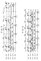
- Fig. 5 Illustrated at (a) in Fig. 5 is the RF field pulse RF, at (b) is the waveform S(t) of the slice selection gradient field, at (c) is the waveform R(t) of the readout gradient field, at (d) is the waveform E(t) of the phase encoding gradient field and at (e) is the NMR signal.
- the slice selection gradient field pulse applied within each of the periods TS2 and TS4 has the duration originally required for slice selection which is added with leading and trailing extensions and similarly, the readout gradient field pulse applied within each of the periods TS2 and TS3 has the duration originally required for signal readout which is added with leading and trailing extensions.
- the error signal and the artifact signal can be dephased. Accordingly, by setting the imaging condition of the multi-echo method in compliance with the present embodiment, a correct image can be obtained.
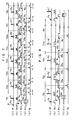
- sampling is conducted till the sixth echo.
- Equation (3) may be illustrated exemplarily by using waveforms as shown at sections (a) through (e) in Fig. 6.
- the waveform of the slice selection gradient field pulse is designed purposely.
- the slice selection gradient field pulses within the periods TS3 and TS4 need the product of intensity and time 2So and the slice selection field gradient field pulses within the periods TS2 and TS5 need the product of intensity and time 3So, wherein not only the duration originally required for slice selection i.e., the duration in synchronism with each of the inversion pulses P2 to P5 is added with leading and trailing extensions but also the intensity is made to be higher at the added extensions than at the duration in synchronism with P2, P3, P4 or P5. Since the intensity of the slice selection gradient field pulse remains unchanged at the duration in synchronism with each inversion pulse throughout the periods TS1 to TS6, all of the inversion pulses P1 to P6 may be of the same frequency band.
- Gradient field pulses for elimination of error component are applied in the same direction as the phase encoding gradient field, as shown at (d) in Fig. 7, before and after each of the inversion pulses P2, P4, P5 and P7 so as not to overlap each inversion pulse.
- the exciting pulse Pe as well as the inversion pulse is subjected to band limitation so that the band-limited inversion pulse behaves as the selective pulse. Accordingly, a spin at a position remote from a selected slice is not affected over the whole measurement time and the measuring method called multi-slice method can be applied wherein during the wait time designated by TR in Figs. 5 to 7 which needs to intervene between cycles of sequence conducted under sequentially changed phase encoding gradient field, measurement of selective excitation and inversion of a different slice which is parallel to a first slice can be carried out. In this manner, multi-echo images of a plurality of slices which are parallel to each other can be measured without suffering from a substantial increase in the whole measurement time.
- the slice selection based on the frequency-limited RF pulse is of imperfect rectangle, raising a problem that interference occurs between the plurality of slices.
- the inversion pulses are sequentially applied to accumulate their imperfectness and a special countermeasure against this problem is needed.
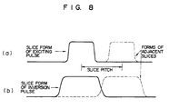
- Fig. 8 diagrammatically shows the countermeasure applicable to the multi-slice method.
- a slice selection characteristic due to band limitation of the exciting pulse Pe of Figs. 5 to 7 is illustrated by solid curve at (a)
- a slice selection characteristic due to band limitation of the inversion pulses P1 to P4 (or P1 to P6 or P1 to P8) is illustrated by solid curve at (b).
- dotted curve at (a) is a slice characteristic due to the exciting pulse in the multi-echo measurement at the second slice conducted during the wait time of Figs. 5 to 7
- dotted curve at (b) is a slice characteristic due to the inversion pulse in that multi-echo measurement.
- the slice thickness of the inversion pulse and the slice pitch (center to center distance) between slices are set to be larger than the thickness of the exciting pulse. Especially, by optimizing the frequency band characteristic of the inversion pulse such that the slice selection characteristic is substantially flattened within the range of the slice thickness of the exciting pulse, mixing of error signal concomitant with the slice form of the inversion pulse can be mitigated.
- the band-limited RF pulse is used as the inversion pulse which is used with the gradient field to invert the spin in the slice.
- the present invention may be applied to permit multi-echo measurement capable of minimizing the error component.
- Fig. 9 shows a further embodiment of the invention wherein the inversion pulse in the multi-echo method for conducting sampling till the fourth echo described previously in connection with Fig. 5 is replaced with a non-selective inversion pulse.
- non-selective inversion pulses P1′, P2′, P3′ and P4′ containing wide band frequencies are applied in place of the inversion pulses P1, P2, P3 and P4 in the form of the band-limited RF pulses, and that the gradient field pulse applied in the same direction as that of the slice selection gradient field has the product of intensity and time So or 2So before and after the inversion pulse P1′, P2′, P3′ or P4′ so that the application period of the gradient field does not overlap that of the inversion pulse.
- the replacement with the non-selective pulse may be effected in connection with the embodiments shown in Figs. 6 and 7. With the non-selective inversion pulse used, the multi-slice measurement utilizing the aforementioned measurement wait time can not be applied but instead more ideal spin inversion can be realized.
- the gradient coils 12, 13 and 14 of Fig. 4 are respectively dedicated to the generation of slice selection gradient field, the generation of readout gradient field and the generation of phase encoding gradient field.
- three kinds of gradient fields orthogonal to each other may be generated on the basis of a resultant field generated by a plurality of gradient field coils as well known in the art.
- the gradient field coils may have waveforms S′(t), R′(t) and E′(t), respectively, which are defined by the following matrix of rotation:
- the individual value of the product of intensity and time of the gradient field pulse are integer times the minimum one. But we can make the individual value of the product of intensity and time not integer times, for example 1.5, 2.7, the minimum one.
Landscapes
- Physics & Mathematics (AREA)
- Health & Medical Sciences (AREA)
- General Health & Medical Sciences (AREA)
- Nuclear Medicine, Radiotherapy & Molecular Imaging (AREA)
- Radiology & Medical Imaging (AREA)
- Engineering & Computer Science (AREA)
- Signal Processing (AREA)
- High Energy & Nuclear Physics (AREA)
- Condensed Matter Physics & Semiconductors (AREA)
- General Physics & Mathematics (AREA)
- Magnetic Resonance Imaging Apparatus (AREA)
Applications Claiming Priority (2)
| Application Number | Priority Date | Filing Date | Title |
|---|---|---|---|
| JP239977/89 | 1989-09-18 | ||
| JP1239977A JPH03103236A (ja) | 1989-09-18 | 1989-09-18 | 核磁気共鳴マルチエコー撮影方法 |
Publications (2)
| Publication Number | Publication Date |
|---|---|
| EP0418675A2 true EP0418675A2 (fr) | 1991-03-27 |
| EP0418675A3 EP0418675A3 (en) | 1991-09-18 |
Family
ID=17052643
Family Applications (1)
| Application Number | Title | Priority Date | Filing Date |
|---|---|---|---|
| EP19900117312 Withdrawn EP0418675A3 (en) | 1989-09-18 | 1990-09-07 | Nuclear magnetic resonance multi-echo imaging method and apparatus |
Country Status (3)
| Country | Link |
|---|---|
| US (1) | US5109197A (fr) |
| EP (1) | EP0418675A3 (fr) |
| JP (1) | JPH03103236A (fr) |
Cited By (2)
| Publication number | Priority date | Publication date | Assignee | Title |
|---|---|---|---|---|
| EP0529527A1 (fr) * | 1991-08-23 | 1993-03-03 | Kabushiki Kaisha Toshiba | Procédé et appareil d'imagerie rapide par résonance magnétique à qualité d'image améliorée |
| CN115880272A (zh) * | 2022-12-30 | 2023-03-31 | 深圳市联影高端医疗装备创新研究院 | 医学图像处理方法、装置、计算机设备和存储介质 |
Families Citing this family (8)
| Publication number | Priority date | Publication date | Assignee | Title |
|---|---|---|---|---|
| JP2709767B2 (ja) * | 1991-09-13 | 1998-02-04 | 株式会社日立メディコ | 磁気共鳴イメージング装置における傾斜磁場印加方法 |
| US5493224A (en) * | 1992-03-03 | 1996-02-20 | Hitachi, Ltd. | Ultra high-speed magnetic resonance imaging method and apparatus |
| JP2677148B2 (ja) * | 1992-11-30 | 1997-11-17 | 株式会社島津製作所 | Mrイメージング装置 |
| DE19649699C2 (de) * | 1996-11-29 | 2003-01-30 | Siemens Ag | Pulssequenz für ein diagnostisches Magnetresonanzgerät |
| JP2001258863A (ja) * | 2000-03-10 | 2001-09-25 | Ge Medical Systems Global Technology Co Llc | Mrイメージング方法およびmri装置 |
| JP4755968B2 (ja) * | 2006-12-07 | 2011-08-24 | 株式会社東芝 | 二重化制御装置、及びそのメモリ部の複数ビットエラーの自動修復方法 |
| CA2618163A1 (fr) | 2008-02-07 | 2009-08-07 | K. W. Michael Siu | Biomarqueurs de cancer de la tete et du cou |
| WO2010061446A1 (fr) | 2008-11-27 | 2010-06-03 | 富士通株式会社 | Appareil de traitement d’informations, procédé de commutation d’unité de traitement, et programme de commutation d’unité de traitement |
Family Cites Families (7)
| Publication number | Priority date | Publication date | Assignee | Title |
|---|---|---|---|---|
| US4876509A (en) * | 1986-12-17 | 1989-10-24 | Resonex, Inc. | Image restoration process for magnetic resonance imaging resonance imaging |
| NL8703127A (nl) * | 1987-12-24 | 1989-07-17 | Philips Nv | Werkwijze en inrichting voor het genereren van vervlochten multiple-slice en multiple-echo pulssequenties voor mri. |
| JPH076765B2 (ja) * | 1988-06-23 | 1995-01-30 | 株式会社日立メディコ | 非破壊断面形状検査装置 |
| US4862081A (en) * | 1988-11-23 | 1989-08-29 | Picker International, Inc. | DC artifact removal in magnetic resonance imaging |
| US4937526A (en) * | 1988-11-23 | 1990-06-26 | Mayo Foundation For Medical Education And Research | Adaptive method for reducing motion and flow artifacts in NMR images |
| US5025216A (en) * | 1989-07-28 | 1991-06-18 | The Board Of Trustees Of The Leland Stanford Junior University | Magnetic resonance imaging of short T2 species |
| US4987371A (en) * | 1989-11-27 | 1991-01-22 | General Electric Company | Method for in-vivo shimming |
-
1989
- 1989-09-18 JP JP1239977A patent/JPH03103236A/ja active Pending
-
1990
- 1990-09-07 EP EP19900117312 patent/EP0418675A3/en not_active Withdrawn
- 1990-09-07 US US07/578,766 patent/US5109197A/en not_active Expired - Fee Related
Cited By (3)
| Publication number | Priority date | Publication date | Assignee | Title |
|---|---|---|---|---|
| EP0529527A1 (fr) * | 1991-08-23 | 1993-03-03 | Kabushiki Kaisha Toshiba | Procédé et appareil d'imagerie rapide par résonance magnétique à qualité d'image améliorée |
| US5361028A (en) * | 1991-08-23 | 1994-11-01 | Kabushiki Kaisha Toshiba | Method and apparatus for high speed magnetic resonance imaging with improved image quality |
| CN115880272A (zh) * | 2022-12-30 | 2023-03-31 | 深圳市联影高端医疗装备创新研究院 | 医学图像处理方法、装置、计算机设备和存储介质 |
Also Published As
| Publication number | Publication date |
|---|---|
| US5109197A (en) | 1992-04-28 |
| EP0418675A3 (en) | 1991-09-18 |
| JPH03103236A (ja) | 1991-04-30 |
Similar Documents
| Publication | Publication Date | Title |
|---|---|---|
| JP3529446B2 (ja) | Epi及びgrase mriにおける読み出し傾斜磁界極性の補正方法 | |
| EP1089087B1 (fr) | Réduction d'artefacts dus à une erreur de phase à cause du terme Maxwell provoquée par un gradient de lecture dans l'IRM | |
| US4684891A (en) | Rapid magnetic resonance imaging using multiple phase encoded spin echoes in each of plural measurement cycles | |
| DE19821780B4 (de) | Korrektur von durch Maxwell-Terme bei einer Schnitt-Verschiebungs-Echo-Planar-Abbildung verursachten Artefakten | |
| EP0490528A1 (fr) | Correction de résultats de mesure dans le domaine de la résonance magnétique nucléaire acquis par une technique du type echo-planar | |
| EP0366232A2 (fr) | Procédé pour la production d'images en tranches multiples par RMN | |
| EP0185194A2 (fr) | Procédé pour réduire les artefacts de mouvement dans les techniques d'imagerie RMN par transformée de Fourier | |
| EP0349976A2 (fr) | Méthode de reconstruction d'image en imagerie par RMN | |
| JP3850495B2 (ja) | Nmrデータから画像を生成する方法及び装置 | |
| US5237273A (en) | Interleaved acquisition of multi-slice NMR data | |
| US20050001619A1 (en) | MRI method and apparatus with elimination of the ambiguity artifact | |
| EP0112663B1 (fr) | Procédé et appareil à résonance magnétique nucléaire | |
| US5668474A (en) | Method in the form of a pulse sequence for fast nuclear magnetic resonance imaging | |
| EP0182267B1 (fr) | Procédé pour supprimer les effets des composants d'erreur de la ligne de base en vue des applications d'imagerie RMN | |
| EP1102082B1 (fr) | Procédé et dispositif pour la réduction d'artefacts d'image causés par vibration de l'aimant dans un système d'imagerie par résonance magnétique | |
| EP0646807A1 (fr) | Appareil d'imagerie par résonance magnétique | |
| US6329821B1 (en) | Method and apparatus to compensate for image artifacts caused by magnet vibration in an MR imaging system | |
| EP0418675A2 (fr) | Procédé et appareil pour la production d'images par échos multiples de résonance magnétique nucléaire | |
| EP0511872A2 (fr) | Imagerie à haute résolution comportant des séquences d'impulsions bréves TE et TR avec acquisition d'écho asymétrique RMN | |
| EP0182107A1 (fr) | Procédé pour réduire les composants d'erreur de la ligne de base de signaux de RMN | |
| JPH07265281A (ja) | Mrイメージング装置 | |
| EP0133532B1 (fr) | Procédé et appareil pour la production d'images par résonance magnétique nucléaire | |
| EP0135143B1 (fr) | Procédé et appareil pour la production d'images par résonance magnétique nucléaire | |
| US6239597B1 (en) | Method and apparatus for rapid T2 weighted MR image acquisition | |
| US5755665A (en) | Apparatus and method for simultaneous detection of multiple magnetic resonance images |
Legal Events
| Date | Code | Title | Description |
|---|---|---|---|
| PUAI | Public reference made under article 153(3) epc to a published international application that has entered the european phase |
Free format text: ORIGINAL CODE: 0009012 |
|
| AK | Designated contracting states |
Kind code of ref document: A2 Designated state(s): DE GB |
|
| PUAL | Search report despatched |
Free format text: ORIGINAL CODE: 0009013 |
|
| AK | Designated contracting states |
Kind code of ref document: A3 Designated state(s): DE GB |
|
| 17P | Request for examination filed |
Effective date: 19920110 |
|
| 17Q | First examination report despatched |
Effective date: 19950127 |
|
| STAA | Information on the status of an ep patent application or granted ep patent |
Free format text: STATUS: THE APPLICATION IS DEEMED TO BE WITHDRAWN |
|
| 18D | Application deemed to be withdrawn |
Effective date: 19960217 |