EP0418700B1 - Moule avec contre-bombage - Google Patents
Moule avec contre-bombage Download PDFInfo
- Publication number
- EP0418700B1 EP0418700B1 EP90117403A EP90117403A EP0418700B1 EP 0418700 B1 EP0418700 B1 EP 0418700B1 EP 90117403 A EP90117403 A EP 90117403A EP 90117403 A EP90117403 A EP 90117403A EP 0418700 B1 EP0418700 B1 EP 0418700B1
- Authority
- EP
- European Patent Office
- Prior art keywords
- sheet
- shaping
- pan member
- supporting surface
- mold
- Prior art date
- Legal status (The legal status is an assumption and is not a legal conclusion. Google has not performed a legal analysis and makes no representation as to the accuracy of the status listed.)
- Expired - Lifetime
Links
Images

Classifications
-
- C—CHEMISTRY; METALLURGY
- C03—GLASS; MINERAL OR SLAG WOOL
- C03B—MANUFACTURE, SHAPING, OR SUPPLEMENTARY PROCESSES
- C03B23/00—Re-forming shaped glass
- C03B23/02—Re-forming glass sheets
- C03B23/023—Re-forming glass sheets by bending
- C03B23/025—Re-forming glass sheets by bending by gravity
- C03B23/0252—Re-forming glass sheets by bending by gravity by gravity only, e.g. sagging
-
- C—CHEMISTRY; METALLURGY
- C03—GLASS; MINERAL OR SLAG WOOL
- C03B—MANUFACTURE, SHAPING, OR SUPPLEMENTARY PROCESSES
- C03B23/00—Re-forming shaped glass
- C03B23/02—Re-forming glass sheets
- C03B23/023—Re-forming glass sheets by bending
- C03B23/025—Re-forming glass sheets by bending by gravity
- C03B23/027—Re-forming glass sheets by bending by gravity with moulds having at least two upward pivotable mould sections
Definitions
- This invention relates to the shaping of glass sheets and in particular to bending iron molds for forming reverse curvatures in hot glass sheets.
- Bent glass sheets are commonly used as glazing closures in vehicles such as automobiles and the like.
- the glass sheets must be bent to precisely defined curvatures dictated by the configuration and outline of the openings in the vehicles in which the bent sheets are to be installed as well as the overall vehicle styling.
- the bent sheets meet stringent optical requirements so that the viewing area of the resulting shaped window is free of optical defects that would interfere with good vision through the window.
- the windows may be heat strengthened to increase their resistance to damage resulting from impact.
- contoured bending molds that support a flat glass sheet and convey it through a heating lehr.
- the bending molds may include hinged end sections to help facilitate bending portions of the glass sheet to sharp curvatures that could not normally be obtained through normal sag bending techniques.
- two glass sheets or doublets may be conveyed through the lehr on the bending mold and shaped simultaneously.
- the object of the present invention is to provide a method and an outline gravity-type bending mold for shaping a hot glass sheet and imparting a specific configuration to selected portions of the glass sheet.
- U.S. Patent Nos. 3,976,462 to Sitara and 4,375,978 to Reese et al. disclose bending iron molds used in sag bending operations. Each includes contoured shaping rails supported by posts on a main support frame that is conveyed through a heating lehr. Flat glass sheets are positioned on the shaping rail of the bending mold and sag into contact with the rails as the glass sheets are heated in the lehr.
- U.S. Patent No. 4,305,746 to Hagedorn et al. teaches a press bending arrangement including a ring type mold construction and a plurality of shaping pads mounted within the outline of the shaping ring.
- the heat softened glass sheet is conveyed into a shaping station wherein the glass sheet is preliminarily bent by contoured conveying rolls.
- the glass sheet is then stopped, vertically lifted off the rolls by the shaping ring and shaping pads and pressed against an upper shaping mold.
- the ring mold and shaping pads thereafter lower the shaped glass sheet back onto the conveyor rolls which continue to convey the glass sheet downstream to a cooling area.
- U.S. Patent No. 4,508,556 to Bennett et al. teaches a method and apparatus for bending glass sheets to complicated shapes including an S-shaped transverse bend.
- Flat glass sheets are heated in a furnace and conveyed into a shaping station wherein the glass is supported on a formed gas hearth support bed.
- a curved outline lifting mold is positioned around the gas hearth support bed and lifts the hot glass sheets off the bed and into contact with an upper vacuum mold to form the desired "S" configuration.
- the outline mold is then lowered and a shuttle ring is positioned beneath the held glass on the upper vacuum mold to receive the glass and remove it from the shaping station for further processing.
- U.S. Patent No. 4,606,749 to Nushi et al. teaches a method and apparatus for shaping glass wherein heat softened glass sheets are lifted off supporting conveyor rolls and pressed between a pair of vertically aligned press faces.
- the lower press face is slotted to receive the conveyor rolls when the press face is in a lowered position.
- a first ring mold positioned about the periphery of the lower press face initially lifts the glass off the rolls and a main ring mold positioned about the lower press face forms the periphery of the glass.
- U.S. Patent No. 3,003, 286 to Richardson teaches a concave, elongated, skeleton type, glass bending mould comprising a pair of generally parallel side bars, a framework supporting said side bars and movable end portions for initially supporting a cold sheet of glass horizontally and for bending such glass with a longitudinal curvature, said mould further including a chilling assembly mounted intermediate of said side bars and spaced a substantial distance transversely from each said bar and comprising a body of metal of thermal capacity large in relation to the side bars and framework of the mould, pivoted links connecting said body to said framework, a cam operative upon rotation to move said body between a raised position a short distance below the level of a straight line joining the neighbouring upper edges of said bars and a lowered position withdrawn a substantial distance below such level, a shaft connected to said cam, and means accessible from the exterior of the mould for rotating said shaft.
- the present invention provides a method of shaping glass sheets by sag bending, including the steps of positioning a glass sheet to be shaped on a support frame having a shaping rail with a first supporting surface that conforms in elevation and outline to the desired shape of said sheet to be shaped slightly inboard of the sheet perimeter, moving said frame with said glass sheet supported thereon through a heating means to heat said sheet to its deformation temperature so that said glass sheet sags into contact with said shaping rail, characterized by sagging selected portions of the heat softened glass sheet inboard of said glass sheet perimeter by bringing said portions into contact with a second sheet supporting surface of a pan member positioned inboard of said shaping rail, wherein the shape and contour and said selected position of the second sheet supporting surface of the pan member is such, that selected portions of the heat softened glass sheet conforming to the contours of the second sheet supporting surface are shaped thereby to a configuration that deviates from the configuration this selected portions of the glass sheet would adapt if no pan member was provided.
- Preferably said selected portions of the glass sheet are outside the center between the central rails of the shaping rail.
- a method of shaping a sheet by sag bending comprising supporting a sheet at its perimeter, heating said sheet to its heat softening temperature while supporting said sheet and allowing a first portion of said sheet inside of said perimeter to sag in a predetermined direction, characterized by engaging a second portion of said sheet by a pan member inside said perimeter to limit sagging of said second portion in said predetermined direction such that said first portion sags in said predetermined direction more than said second portion sags in said predetermined direction which results in a sheet having a reverse bend.
- an outline gravity-type bending mold for shaping a hot glass sheet
- the mold comprises a support frame for movement through a heating means, a shaping rail having a first sheet supporting surface, means for mounting the shaping rail on the support frame such that said first sheet supporting surface has a predetermined elevation, characterized by a pan member having a second sheet supporting surface and means for mounting that pan member on the frame in spaced relation to and inboard of the shaping rail in a selected position relative to the first supporting surface of the shaping rail, the shape and contour and said selected position of the second sheet supporting surface of the pan member being such, that a selected portion of the glass sheet contacts the second sheet supporting surface and is shaped thereby to a configuration that deviates from the configuration this selected part of the glass sheet would adapt if no pan member was provided.
- said shaping rail includes a pair of spaced central shaping rails and a pair of pivotally mounted end shaping rails, whereby the pan member is positioned to extend along the central shaping rails outside the center between both central shaping rails.
- the pan member has an upper glass sheet engaging surface that is curved so that as the heated glass sheet sags on the bending mold, the glass sheet is generally concave upward at those portions not in contact with the pan member, and generally convex upward at those portions that sag onto and are supported by the pan member.
- the glass engaging surface includes a heat resistant cover interposed between the glass sheet and the pan member.
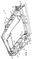
- Figure 1 is an isometric view of a bending mold incorporating portions of the present invention with portions removed for clarity.
- Figure 2 is a cross-section of a conventional bending mold.
- Figure 3 is a cross-section of the bending mold shown in Figure 1, with portions removed for clarity.
- Figure 4 is a partial cross-section similar to figure 3 of an alternate embodiment of the invention.
- Figure 5 is a cross-section similar to Figure 3 of an alternate embodiment of the present invention.
- glass bending mold 10 is an articulating mold similar to that disclosed in U. S. Patent No. 3,976,462 to Sitara, but nonarticulating molds similar to U. S. Patent No. 4,375,978 to Reese et al may also be used in the present invention.
- the mold 10 comprises a central mold portion 12 flanked by two pivoting mold end sections 14. The mold 10 is supported for movement through a heating lehr (not shown) by a main frame 16.
- Weight arms 18 are attached to each mold end section 14 and are mounted on frame 16 by hinge posts 20. Arms 18 are provided with counterweights 22 at their longitudinal inward extremities which tend to rotate the mold end sections 14 about hinge posts 20 from an open position (not shown) to a closed position as depicted in Figure 1. Weight arms 18 are positioned laterally outside shaping rails 24 of the bending mold 10.
- Shaping rails 24 of the mold 10 include central shaping rails 26 supported from rigid reinforcing bars 28 by members 30 in the central portion 12 and end shaping rails 32 supported from reinforcing bars 34 by members 36 in each mold end section 14. Reinforcing bars 28 in the central mold section 12 are rigidly attached to frame 16 while reinforcing bars 34 in each end mold section 14 are pivotally mounted on frame 16 through hinge post 20. When the mold sections 14 are in their pivoted upright and closed position as shown in Figure 1, the elevational contour of the shaping rail 24 defines the final desired contour of the shaped glass sheet slightly inboard of the glass sheet perimeter.
- Figure 2 shows a conventional bending mold 38 and illustrates the configuration of a pair of glass sheets G, or doublets that are formed by conventional sag bending techniques. As can be seen, the glass sheets G have a simple configuration with no reverse curvatures.
- a pan member 42 is positioned on the mold 10 within the shaping rails 24.
- Glass sheet engaging surface 44 of the pan 42 may be contoured such that at least a portion of the engaging surface 44 is convex upward to form a reverse curvature in the glass sheets G as will be discussed later.
- the pan 42 is positioned to extend along and generally between shaping rails 26 of the central mold section 12.
- the pan 42 is made of a heat resistant material, such as, but not limited to steel or ceramic.
- cover 46 includes a fiberglass cloth or a dense ceramic fiber paper, such as that available from Sohio Engineered Material Co. under the tradename FIBERFRAX 970-J, and an insulating blanket 50 such as that available from Babcock and Wilcox under the tradename KAOWOOL ZR.
- the pan 42 may be supported on mold 10 in any convenient fashion. Although not limiting in the present invention, in the particular embodiment illustrated, Figures 1 and 3, the pan 42 is supported on cross members 52 of main frame 16 by support arms 54 and 56.
- one or more glass sheets are positioned as mold 10 and heated to its heat softening temperature.
- Engaging surface 44 of the pan 42 is preferably located below the highest points of the shaping rail 24 of mold 10 so that when the rail 24 is supporting rigid flat glass sheets G, lower major surface 54 of the glass sheets G does not contact the surface 44 until the glass sheets G are heated and begins to sag thereon.
- the interior portions of the glass sheets that do not sage into contact with the pan member 42 will assume a concave upward curvature while those portions of the glass sheet that sag into contact with the pan member 42 assume a convex upward configuration, corresponding to the curvature of the engaging surface 44.
- the glass sheets G are formed to a reserve curvature configuration between the unsupported portion and the portion that contacts and is supported by the pan 42. After the forming operation is complete, the glass sheets G are cooled.
- the pan 42 may be moved away from the glass sheets G to provide better circulation of air around the glass sheets for more effective cooling.
- hook 60 may be disengaged, either mechanically or electrically, from end 62 of pivoting support arm 64 which supports the pan 42, allowing the pan 42 to rotate downward about post 66 and away from the glass sheet G. In Figure 4, this rotation would be in a counterclockwise direction.
- the pan 42 may move downward by its own weight, or, if necessary, auxiliary means may be used to rotate pan 42, such as, but not limited to, springs connecting (not shown) arm 64 with frame member 52.
- pan member 42 acts as a heat sink during the heating and sag bending operation, causing non-uniform cooling of the shaped glass G by reducing the cooling rate of the glass G.
- an insulating blanket is positioned within the area of the mold 10 defined by rail 24 as shown in Figure 5.
- a portion 70 of blanket 68 is draped over the pan member 42 to insulate the glass sheets G from the surface 44 with remaining blanket portions 72 positioned in spaced apart relation below the glass sheets G, and preferably extending to the shaping rails 24.
- the blanket 68 "evens out” the cooling rate of the glass sheets G by keeping the entire sheets at a more uniform temperature as the sheets are cooled after shaping. Any gaps in the rail 24 or spaces in the blanket 68 should be filled to prevent air flow under the glass sheets G that would adversely affect the uniform glass cooling rate.
- the blanket 68 is a KAOWOOL® RZ insulting material blanket supported below glass sheets G by a framework 74, which may be, for example expanded metal or were as shown in Figure 5.
- the engaging surface 44 or the pan member 42 may be used to limit the sag of the glass sheet G without imparting a reverse curvature.
- the engaging member 44 may be concave so that the entire glass sheet is concave upward, with the engaging surface 44 imparting a specific curvature in the glass sheet G.
- the engaging surface 44 of the pan member 42 may be flat so as to eliminate any curvature in a selected portion of the glass sheet G.
- the bending operation described herein may be used for single or multiple sheets of glass. It is contemplated that if required, the bottom ply of glass may act as a disposable burn plate to take any marking from the pan 42 and/or shaping rails 24.
Landscapes
- Chemical & Material Sciences (AREA)
- Engineering & Computer Science (AREA)
- Materials Engineering (AREA)
- Organic Chemistry (AREA)
- Re-Forming, After-Treatment, Cutting And Transporting Of Glass Products (AREA)
Claims (15)
- Moule (10) de bombage sur squelette, du type par gravité, pour le formage à chaud d'une feuille de verre, comprenant un cadre support (16) destiné à être déplacé à travers un moyen de chauffage, un rail de formage ou squelette (24) présentant une première surface de support pour la feuille de verre, un moyen pour monter le rail de formage (24) sur le cadre support (16) de façon que la première surface de support se trouve à une hauteur prédéterminée, caractérisé par :
un élément formant sole (42), qui présente une seconde surface de support (44) pour la feuille de verre, et un moyen pour monter cet élément formant sole (42) sur le cadre (16), en dedans du rail de formage (24) et avec un espace par rapport à celui-ci, dans une position choisie par rapport à la première surface de support du rail de formage (24), la forme et le contour de ladite position choisie de la seconde surface de support (44) de l'élément formant sole (42) étant tels qu'une partie sélectionnée de la feuille de verre vienne en contact avec la seconde surface de support (44) et soit, grâce à elle, mise en forme en une configuration qui s'écarte de la configuration qu'aurait prise cette partie choisie de la feuille de verre si aucun élément formant sole n'avait été prévu. - Moule selon la revendication 1, caractérisé en ce que le rail de formage ou squelette (24) comporte deux rails centraux espacés de formage (26) et deux rails pivotants de formage (32) montés aux extrémités, l'élément formant sole (42) étant placé de manière à s'étendre le long des rails centraux de formage (26) en dehors de la ligne médiane entre les deux rails centraux de formage (26).
- Moule selon la revendication 2, caractérisé en ce que ledit moyen de montage dudit élément formant sole (42) dans la position choisie, comprend un crochet (60), un bras support pivotant (64), un moyen de montage à pivotement du bras support (64) sur l'élément formant sole (42) et un moyen (66) de montage à pivotement du bras support (64) sur le cadre (16), la partie d'extrémité (62) du bras support (64) étant retenue par le crochet (60) afin de maintenir ledit élément formant sole (42) dans la position choisie.
- Moule selon la revendication 2, caractérisé en ce que le moyen de montage du rail de formage (24) comprend un moyen pour monter les rails centraux (26) sur le cadre (16), un moyen pour monter à pivotement les deux rails d'extrémité (32) sur le cadre support (16) à une certaine distance l'un de l'autre, de part et d'autre des deux rails centraux (26), et un moyen pour déplacer les deux rails d'extrémité (32) depuis une première position dans laquelle les surfaces de support de feuille des deux rails d'extrémité (32) et des deux rails centraux (26) sont généralement alignées pour recevoir une feuille à mettre en forme, jusqu'à une seconde position dans laquelle les surfaces de support des deux rails d'extrémité (32) sont au-dessus de la surface de support des rails centraux (26).
- Moule selon la revendication 2, caractérisé en ce que ledit moyen de montage dudit élément formant sole (42) place ce dernier dans la position choisie de telle manière que la seconde surface de support (44) dudit élément formant sole (42) soit au-dessous des points les plus hauts de la première surface de support du rail de formage (24) afin que la seconde surface de support (44) ne vienne pas en contact avec la surface inférieure de la feuille de verre froide.
- Moule selon la revendication 5, caractérisé en ce qu'au moins une partie de la seconde surface de support (44) dudit élément formant sole (42) est convexe vers le haut.
- Moule selon la revendication 6, caractérisé en ce qu'il comprend en outre un revêtement résistant à la chaleur (46) qui recouvre la seconde surface de support (44) dudit élément formant sole (42).
- Moule selon la revendication 7, caractérisé en ce que le rail de formage (44) définit une aire et en ce que ledit revêtement (46) résistant à la chaleur comporte une couverture isolante s'étendant sensiblement sur toute l'aire définie par le rail de formage (24).
- Procédé de formage de feuilles de verre par bombage par affaissement, comprenant les opérations consistant à mettre en place une feuille de verre à former sur un cadre support (16) qui comporte un rail de formage ou squelette (24) ayant une première surface de support qui correspond, en élévation et en contour, à la forme souhaitée pour la feuille à former, légèrement à l'intérieur du périmètre de la feuille, à déplacer ledit cadre (16), avec la feuille de verre qu'il supporte, à travers un moyen de chauffage pour chauffer ladite feuille jusqu'à sa température de déformation, de manière que ladite feuille de verre s'affaisse pour venir en contact avec ledit rail de formage (24), caractérisé en ce qu'on fait s'affaisser des parties sélectionnées de la feuille de verre ramollie à chaud en dedans dudit périmètre de la feuille de verre, en amenant lesdites parties en contact avec une seconde surface de support (44) pour la feuille de verre, qui fait partie d'un élément formant sole (42) placé en dedans du rail de formage (24), la forme et le contour et la position choisie de la seconde surface de support (44) de l'élément formant sole (42) étant tels que des parties sélectionnées de la feuille de verre ramollie à chaud, en prenant la forme des contours de la seconde surface de support (44), soient mise en forme par celle-ci en une configuration qui s'écarte de la configuration que ces parties choisies de la feuille de verre auraient prises si aucun élément formant sole (42) n'avait été prévu.
- Procédé selon la revendication 9, caractérisé en ce que les parties choisies de ladite feuille de verre se trouvent en dehors du milieu entre les rails centraux de formage (26) du rail de formage (24).
- Procédé selon la revendication 10, caractérisé en ce qu'il comprend en outre l'étape consistant à mettre ledit élément formant sole (42) hors de contact de ladite feuille de verre lorsque cette dernière a épousé les contours dudit élément formant sole (42).
- Procédé selon la revendication 10, caractérisé en ce qu'il comprend, en outre, l'étape qui consiste à refroidir ladite plaque de verre.
- Procédé selon la revendication 10, caractérisé en ce que le rail de formage (24) définit une aire et en ce qu'il comprend, en outre, l'étape consistant à poser un revêtement résistant à la chaleur (46) à l'intérieur de l'aire définie par le rail de formage (24).
- Procédé de formage d'une feuille par bombage par affaissement, comprenant les opérations consistant :
à supporter une feuille par son périmètre,
à chauffer ladite feuille jusqu'à sa température de ramollissement tout en supportant ladite feuille et en permettant à une première partie de ladite feuille située à l'intérieur dudit périmètre de s'affaisser dans une direction prédéterminée,
caractérisé en ce qu'on met en contact un élément formant sole (42) avec une seconde partie de ladite feuille, à l'intérieur dudit périmètre de celle-ci, pour limiter l'affaissement de ladite seconde partie dans ladite direction prédéterinée, de telle sorte que ladite première partie s'affaisse davantage, dans ladite direction prédéterminée, que ladite seconde partie dans ladite direction prédéterminée, ce qui conduit à une plaque présentant un contre-bombage. - Procédé selon la revendication 14, caractérisé en ce que ladite étape consistant à supporter une feuille comprend l'opération consistant à mettre en place un revêtement résistant à la chaleur (46) sous la feuille.
Applications Claiming Priority (2)
| Application Number | Priority Date | Filing Date | Title |
|---|---|---|---|
| US07/408,829 US4979977A (en) | 1989-09-18 | 1989-09-18 | Bending iron having member to effect reverse bend and method of using same |
| US408829 | 1989-09-18 |
Publications (2)
| Publication Number | Publication Date |
|---|---|
| EP0418700A1 EP0418700A1 (fr) | 1991-03-27 |
| EP0418700B1 true EP0418700B1 (fr) | 1994-01-19 |
Family
ID=23617947
Family Applications (1)
| Application Number | Title | Priority Date | Filing Date |
|---|---|---|---|
| EP90117403A Expired - Lifetime EP0418700B1 (fr) | 1989-09-18 | 1990-09-10 | Moule avec contre-bombage |
Country Status (5)
| Country | Link |
|---|---|
| US (1) | US4979977A (fr) |
| EP (1) | EP0418700B1 (fr) |
| JP (1) | JPH0829955B2 (fr) |
| CA (1) | CA2024761C (fr) |
| DE (1) | DE69006146T2 (fr) |
Cited By (1)
| Publication number | Priority date | Publication date | Assignee | Title |
|---|---|---|---|---|
| US11597672B2 (en) | 2016-03-09 | 2023-03-07 | Corning Incorporated | Cold forming of complexly curved glass articles |
Families Citing this family (34)
| Publication number | Priority date | Publication date | Assignee | Title |
|---|---|---|---|---|
| FR2658808B1 (fr) * | 1990-02-21 | 1993-05-14 | Saint Gobain Vitrage Int | Four de bombage de feuilles de verre par effondrement sur un cadre de bombage et son application a la realisation de vitrages de forme complexe. |
| FI84807C (fi) * | 1990-03-30 | 1992-01-27 | Tamglass Oy | Foerfarande och formanordning foer att i en glasskiva boeja svaora boejningsformer, saosom s-form. |
| US5185022A (en) * | 1990-03-30 | 1993-02-09 | Tamglass Engineering Oy | Mould assembly for bending difficult bending shapes in a glass sheet |
| JP3813654B2 (ja) * | 1995-02-09 | 2006-08-23 | 日本碍子株式会社 | セラミックスの接合構造およびその製造方法 |
| FR2855168B1 (fr) * | 2003-05-19 | 2007-03-30 | Saint Gobain | Bombage de vitrages par gravite sur une multiplicite de supports |
| US7459199B2 (en) * | 2004-01-29 | 2008-12-02 | Ppg Industries Ohio, Inc. | Method of and apparatus for strengthening edges of one or more glass sheets |
| EP2766316B1 (fr) * | 2011-10-10 | 2020-04-01 | Corning Incorporated | Appareil et procédé de pliage serré de fines feuilles de verre |
| EP2766315B1 (fr) * | 2011-10-10 | 2018-10-03 | Corning Incorporated | Refaçonnage de feuilles de verre minces |
| US9452948B2 (en) * | 2014-02-06 | 2016-09-27 | Glasstech, Inc. | Three stage forming station and method for forming a hot glass sheet with transverse curvature |
| WO2018005646A1 (fr) | 2016-06-28 | 2018-01-04 | Corning Incorporated | Stratification de verre mince renforcé sur une surface en plastique moulée incurvée pour une application de protection d'écran et de décoration |
| WO2018009504A1 (fr) | 2016-07-05 | 2018-01-11 | Corning Incorporated | Article en verre formé à froid et son procédé d'assemblage |
| CN115403280B (zh) | 2016-10-25 | 2024-03-19 | 康宁公司 | 用于显示器的冷成形玻璃积层 |
| US11016590B2 (en) | 2017-01-03 | 2021-05-25 | Corning Incorporated | Vehicle interior systems having a curved cover glass and display or touch panel and methods for forming the same |
| KR20200017001A (ko) | 2017-01-03 | 2020-02-17 | 코닝 인코포레이티드 | 만곡된 커버 유리 및 디스플레이 또는 터치 패널을 갖는 차량 인테리어 시스템 및 이를 형성시키는 방법 |
| RU2742682C1 (ru) | 2017-04-10 | 2021-02-09 | Сэн-Гобэн Гласс Франс | Устройство и способ изгибания прессованием стеклянных листов |
| US11685684B2 (en) | 2017-05-15 | 2023-06-27 | Corning Incorporated | Contoured glass articles and methods of making the same |
| CN111094050B (zh) | 2017-07-18 | 2023-11-07 | 康宁公司 | 复杂弯曲玻璃制品的冷成型 |
| WO2019055581A1 (fr) | 2017-09-12 | 2019-03-21 | Corning Incorporated | Éléments tactiles pour verre à face isolée et procédés pour les fabriquer |
| TWI873668B (zh) | 2017-09-13 | 2025-02-21 | 美商康寧公司 | 用於顯示器的基於光導器的無電面板、相關的方法及載具內部系統 |
| US11065960B2 (en) | 2017-09-13 | 2021-07-20 | Corning Incorporated | Curved vehicle displays |
| EP3692003B1 (fr) * | 2017-10-06 | 2026-03-25 | Corning Incorporated | Système et procédé pour former un article stratifié en verre incurvé utilisant un différentiel de viscosité de verre pour une adaptation de forme améliorée |
| TWI844520B (zh) | 2017-10-10 | 2024-06-11 | 美商康寧公司 | 具有改善可靠性的彎曲的覆蓋玻璃的車輛內部系統及其形成方法 |
| CN111758063B (zh) | 2017-11-21 | 2022-08-09 | 康宁公司 | 用于抬头显示器系统的非球面镜及其形成方法 |
| US11550148B2 (en) | 2017-11-30 | 2023-01-10 | Corning Incorporated | Vacuum mold apparatus, systems, and methods for forming curved mirrors |
| TWI772569B (zh) | 2017-11-30 | 2022-08-01 | 美商康寧公司 | 用於真空成形非球面鏡的系統與方法 |
| CN116299791A (zh) | 2018-03-02 | 2023-06-23 | 康宁公司 | 抗反射涂层及制品与形成抗反射涂层及制品的方法 |
| CN111989302B (zh) | 2018-03-13 | 2023-03-28 | 康宁公司 | 具有抗破裂的弯曲覆盖玻璃的载具内部系统及用于形成这些载具内部系统的方法 |
| WO2020014064A1 (fr) | 2018-07-12 | 2020-01-16 | Corning Incorporated | Écran isolant conçu pour une mise en correspondance de couleurs |
| CN112566782A (zh) | 2018-07-16 | 2021-03-26 | 康宁公司 | 具冷弯玻璃基板的车辆内部系统及其形成方法 |
| EP3771695A1 (fr) | 2019-07-31 | 2021-02-03 | Corning Incorporated | Procédé et système pour verre formé à froid |
| US12466756B2 (en) | 2019-10-08 | 2025-11-11 | Corning Incorporated | Curved glass articles including a bumper piece configured to relocate bending moment from display region and method of manufacturing same |
| CN113557217A (zh) * | 2020-02-19 | 2021-10-26 | 法国圣戈班玻璃厂 | 用于压弯玻璃片材的装置和方法 |
| US11772361B2 (en) | 2020-04-02 | 2023-10-03 | Corning Incorporated | Curved glass constructions and methods for forming same |
| US11542189B2 (en) * | 2020-09-03 | 2023-01-03 | Glasstech, Inc. | Articulated mold arrangement for a glass processing system |
Family Cites Families (12)
| Publication number | Priority date | Publication date | Assignee | Title |
|---|---|---|---|---|
| US2932129A (en) * | 1954-03-15 | 1960-04-12 | Libbey Owens Ford Glass Co | Method of bending and cutting sheets of glass or like materials |
| DE1072366B (fr) * | 1956-06-28 | 1900-01-01 | ||
| NL277698A (fr) * | 1961-05-01 | 1900-01-01 | ||
| US3278289A (en) * | 1962-11-14 | 1966-10-11 | Pittsburgh Plate Glass Co | Pivoted glass sheet bending mold |
| US3278287A (en) * | 1963-05-28 | 1966-10-11 | Libbey Owens Ford Glass Co | Method of producing pattern-cut bent glass sheet |
| US3457060A (en) * | 1966-03-23 | 1969-07-22 | Libbey Owens Ford Co | Glass bending furnace with partitions defining separate longitudinally disposed heating areas |
| US3976462A (en) * | 1975-03-10 | 1976-08-24 | Ppg Industries, Inc. | Method and apparatus for bending glass sheets |
| US4305746A (en) * | 1980-05-01 | 1981-12-15 | Libbey-Owens-Ford Company | Method of and apparatus for bending glass sheets |
| US4375978A (en) * | 1981-07-01 | 1983-03-08 | Ppg Industries, Inc. | Lightweight outline mold with low thermal inertia for shaping glass sheets |
| US4508556A (en) * | 1984-06-04 | 1985-04-02 | Ppg Industries, Inc. | Method and apparatus for bending glass sheets to complicated shapes including an S-shaped transverse bend |
| JPS6183640A (ja) * | 1984-09-26 | 1986-04-28 | Nippon Sheet Glass Co Ltd | 板ガラスのプレス成形方法及び装置 |
| US4711677A (en) * | 1986-07-18 | 1987-12-08 | The Garrett Corporation | High temperature bushing alloy |
-
1989
- 1989-09-18 US US07/408,829 patent/US4979977A/en not_active Expired - Lifetime
-
1990
- 1990-09-06 CA CA002024761A patent/CA2024761C/fr not_active Expired - Fee Related
- 1990-09-10 EP EP90117403A patent/EP0418700B1/fr not_active Expired - Lifetime
- 1990-09-10 DE DE69006146T patent/DE69006146T2/de not_active Expired - Fee Related
- 1990-09-17 JP JP2246939A patent/JPH0829955B2/ja not_active Expired - Fee Related
Cited By (1)
| Publication number | Priority date | Publication date | Assignee | Title |
|---|---|---|---|---|
| US11597672B2 (en) | 2016-03-09 | 2023-03-07 | Corning Incorporated | Cold forming of complexly curved glass articles |
Also Published As
| Publication number | Publication date |
|---|---|
| CA2024761C (fr) | 1995-01-17 |
| DE69006146T2 (de) | 1994-07-21 |
| DE69006146D1 (de) | 1994-03-03 |
| JPH0829955B2 (ja) | 1996-03-27 |
| CA2024761A1 (fr) | 1991-03-19 |
| US4979977A (en) | 1990-12-25 |
| JPH03122023A (ja) | 1991-05-24 |
| EP0418700A1 (fr) | 1991-03-27 |
Similar Documents
| Publication | Publication Date | Title |
|---|---|---|
| EP0418700B1 (fr) | Moule avec contre-bombage | |
| EP0885851B1 (fr) | Procédé et appareil de bombage de feuilles de verre | |
| CA1287214C (fr) | Methode et dispositif de mise en forme du verre en feuille | |
| CA1287980C (fr) | Galbage nouveau genre a la presse | |
| US4508556A (en) | Method and apparatus for bending glass sheets to complicated shapes including an S-shaped transverse bend | |
| US5755845A (en) | Method and apparatus for bending and tempering glass sheets | |
| US4746348A (en) | Horizontal press bending apparatus and method | |
| CA1204936A (fr) | Prevention de la surchauffe d'un moule a vide servant a la mise en forme des panneaux de verre | |
| US8119224B2 (en) | Process for bending a glass panel with a plurality of supports | |
| US5437703A (en) | Bending glass sheets | |
| US4501603A (en) | Method and apparatus for shaping glass sheets to complicated shapes | |
| JPH0647474B2 (ja) | 加熱軟化シート材料を所定の形に形づける方法及び装置 | |
| US4349375A (en) | Deformable vacuum mold for shaping glass sheets | |
| KR910003090B1 (ko) | 유리판 굴곡장치(Temparatus for Bending Glass Sheets) | |
| CA1283294C (fr) | Moule-presse a surface developpee | |
| GB2058743A (en) | Method and apparatus for shaping glass sheets | |
| EP0414877B1 (fr) | Moule de pliage par compression d'une feuille de verre | |
| EP0179794B1 (fr) | Appareil de pliage de feuilles de verre | |
| CA2151620C (fr) | Presse a moule flexible | |
| US4973344A (en) | Method and apparatus for bending glass sheets | |
| US4983200A (en) | Glass shaping ring having a thermal insulating member and method of shaping glass sheets using same | |
| US4488892A (en) | Pivotal shaped auxiliary gas heater for glass sheet shaping molds | |
| US3248202A (en) | Pivoted glass sheet bending mold |
Legal Events
| Date | Code | Title | Description |
|---|---|---|---|
| PUAI | Public reference made under article 153(3) epc to a published international application that has entered the european phase |
Free format text: ORIGINAL CODE: 0009012 |
|
| AK | Designated contracting states |
Kind code of ref document: A1 Designated state(s): DE FR GB IT |
|
| 17P | Request for examination filed |
Effective date: 19910822 |
|
| 17Q | First examination report despatched |
Effective date: 19921222 |
|
| GRAA | (expected) grant |
Free format text: ORIGINAL CODE: 0009210 |
|
| AK | Designated contracting states |
Kind code of ref document: B1 Designated state(s): DE FR GB IT |
|
| REF | Corresponds to: |
Ref document number: 69006146 Country of ref document: DE Date of ref document: 19940303 |
|
| ITF | It: translation for a ep patent filed | ||
| ET | Fr: translation filed | ||
| PLBE | No opposition filed within time limit |
Free format text: ORIGINAL CODE: 0009261 |
|
| STAA | Information on the status of an ep patent application or granted ep patent |
Free format text: STATUS: NO OPPOSITION FILED WITHIN TIME LIMIT |
|
| 26N | No opposition filed | ||
| REG | Reference to a national code |
Ref country code: FR Ref legal event code: TP |
|
| REG | Reference to a national code |
Ref country code: GB Ref legal event code: 732E |
|
| REG | Reference to a national code |
Ref country code: GB Ref legal event code: IF02 |
|
| PGFP | Annual fee paid to national office [announced via postgrant information from national office to epo] |
Ref country code: DE Payment date: 20020930 Year of fee payment: 13 |
|
| PGFP | Annual fee paid to national office [announced via postgrant information from national office to epo] |
Ref country code: GB Payment date: 20030902 Year of fee payment: 14 |
|
| PGFP | Annual fee paid to national office [announced via postgrant information from national office to epo] |
Ref country code: FR Payment date: 20030918 Year of fee payment: 14 |
|
| PG25 | Lapsed in a contracting state [announced via postgrant information from national office to epo] |
Ref country code: DE Free format text: LAPSE BECAUSE OF NON-PAYMENT OF DUE FEES Effective date: 20040401 |
|
| PG25 | Lapsed in a contracting state [announced via postgrant information from national office to epo] |
Ref country code: GB Free format text: LAPSE BECAUSE OF NON-PAYMENT OF DUE FEES Effective date: 20040910 |
|
| GBPC | Gb: european patent ceased through non-payment of renewal fee |
Effective date: 20040910 |
|
| PG25 | Lapsed in a contracting state [announced via postgrant information from national office to epo] |
Ref country code: FR Free format text: LAPSE BECAUSE OF NON-PAYMENT OF DUE FEES Effective date: 20050531 |
|
| REG | Reference to a national code |
Ref country code: FR Ref legal event code: ST |
|
| PG25 | Lapsed in a contracting state [announced via postgrant information from national office to epo] |
Ref country code: IT Free format text: LAPSE BECAUSE OF NON-PAYMENT OF DUE FEES;WARNING: LAPSES OF ITALIAN PATENTS WITH EFFECTIVE DATE BEFORE 2007 MAY HAVE OCCURRED AT ANY TIME BEFORE 2007. THE CORRECT EFFECTIVE DATE MAY BE DIFFERENT FROM THE ONE RECORDED. Effective date: 20050910 |