EP0418703A2 - Dispositif améliorant les propriétés de tenue de route hivernale des pneumatiques - Google Patents
Dispositif améliorant les propriétés de tenue de route hivernale des pneumatiques Download PDFInfo
- Publication number
- EP0418703A2 EP0418703A2 EP90117437A EP90117437A EP0418703A2 EP 0418703 A2 EP0418703 A2 EP 0418703A2 EP 90117437 A EP90117437 A EP 90117437A EP 90117437 A EP90117437 A EP 90117437A EP 0418703 A2 EP0418703 A2 EP 0418703A2
- Authority
- EP
- European Patent Office
- Prior art keywords
- rim
- actuating devices
- arms
- actuating
- wheel
- Prior art date
- Legal status (The legal status is an assumption and is not a legal conclusion. Google has not performed a legal analysis and makes no representation as to the accuracy of the status listed.)
- Pending
Links
Images

Classifications
-
- B—PERFORMING OPERATIONS; TRANSPORTING
- B60—VEHICLES IN GENERAL
- B60C—VEHICLE TYRES; TYRE INFLATION; TYRE CHANGING; CONNECTING VALVES TO INFLATABLE ELASTIC BODIES IN GENERAL; DEVICES OR ARRANGEMENTS RELATED TO TYRES
- B60C11/00—Tyre tread bands; Tread patterns; Anti-skid inserts
- B60C11/14—Anti-skid inserts, e.g. vulcanised into the tread band
-
- B—PERFORMING OPERATIONS; TRANSPORTING
- B60—VEHICLES IN GENERAL
- B60C—VEHICLE TYRES; TYRE INFLATION; TYRE CHANGING; CONNECTING VALVES TO INFLATABLE ELASTIC BODIES IN GENERAL; DEVICES OR ARRANGEMENTS RELATED TO TYRES
- B60C27/00—Non-skid devices temporarily attachable to resilient tyres or resiliently-tyred wheels
- B60C27/06—Non-skid devices temporarily attachable to resilient tyres or resiliently-tyred wheels extending over the complete circumference of the tread, e.g. made of chains or cables
- B60C27/14—Non-skid devices temporarily attachable to resilient tyres or resiliently-tyred wheels extending over the complete circumference of the tread, e.g. made of chains or cables automatically attachable
-
- Y—GENERAL TAGGING OF NEW TECHNOLOGICAL DEVELOPMENTS; GENERAL TAGGING OF CROSS-SECTIONAL TECHNOLOGIES SPANNING OVER SEVERAL SECTIONS OF THE IPC; TECHNICAL SUBJECTS COVERED BY FORMER USPC CROSS-REFERENCE ART COLLECTIONS [XRACs] AND DIGESTS
- Y10—TECHNICAL SUBJECTS COVERED BY FORMER USPC
- Y10T—TECHNICAL SUBJECTS COVERED BY FORMER US CLASSIFICATION
- Y10T152/00—Resilient tires and wheels
- Y10T152/10—Tires, resilient
- Y10T152/10279—Cushion
Definitions
- the invention relates to a device for improving the winter running properties of vehicle tires with engagement bodies arranged in the grooves of their tread pattern, preferably in the form of a rust-like association of a plurality of engagement rings, each encompassing its tread ring.
- the engagement body the height of which corresponds at most to the tread depth and which are arranged displaceably in the radial direction with respect to the tire axis, is supported by lateral arms on the rim receiving the associated tire and by means of at least one actuating device assigned to one of its arms are displaceable in the radial direction.
- the measures according to the invention ensure a high degree of protection of the engaging edges of the engaging bodies and therefore ensure a long service life of these engaging bodies. Nevertheless, the measures according to the invention ensure the desired traffic safety in winter road conditions. Another advantage of the measures according to the invention can be seen in the fact that the actuating devices provided for actuating the engaging bodies which can be plugged onto the tread pattern and which can be supported on the rim are arranged outside the tire, which enables simple retrofitting of existing tires and comparatively simple assembly.
- the height of the engagement body can advantageously be smaller than the profile depth. This ensures that the engagement body can be completely sunk, which ensures a particularly high level of protection.
- Another particularly expedient measure can consist in the fact that in the case of rust-like engagement bodies, the clear cross-section of the individual rings is sufficiently overdimensioned for a sliding fit compared to the respectively assigned stud cross-section.
- each engaging body can have several, preferably two, arms offset in the circumferential direction, at least in the area of one tire side. This results in a reliable, tilt-proof force transmission in an advantageous manner.
- An actuator can advantageously be assigned to each arm. This ensures that the same engagement depth of the engagement edges can be achieved over the entire tread width.
- the rim can expediently be provided with circumferential supports for the arms of the engaging bodies or the actuating devices. This enables simple assembly and at the same time ensures reliable power transmission.
- At least the carrier arranged on the outside of the rim can advantageously be designed as a ring which can be releasably fixed to the rim.
- the actuating devices can advantageously be preassembled on this ring, so that there is a simple final assembly. At the same time, this measure enables the actuating devices to be accommodated in an area protected by the leading edges of the tire, so that the external actuating devices are also not endangered.
- At least the inner carrier can be designed as a ring molded onto the rim, expediently as an extension of an edge strip of the rim flange.
- a further advantageous measure can consist in that the rotating supports are provided with a protective flange which at least partially covers the actuating devices accommodated on them. This reliably prevents both contamination and damage to the actuating devices.
- the actuating devices can be at least partially designed as cylinder-piston units that can be actuated by means of a preferably hydraulic pressure medium.
- a preferably hydraulic pressure medium This is not only particularly proven and robust, but also particularly cost-effective other components.
- such an embodiment advantageously enables a relatively simple operation of a central actuation, which ensures a high level of user-friendliness.
- an ice sensor arranged on the vehicle can advantageously be provided, by means of which the actuation devices can be activated. This measure results in a particularly high level of user friendliness and security.
- the vehicle wheel on which FIG. 1 is based comprises a tire 1 produced as a vulcanization molding, which is received on a rim ring 2 which is plate-shaped in cross section.
- the rim ring 2 is fastened to a disk-shaped rim body 3, which can be fixed here to a wheel hub 4, which is carried by a driven shaft 5.
- the tire 1 is profiled in the area of the tread. This profile comprises studs 6 and grooves 7 extending between them.
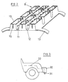
- engaging bodies 8 are provided in the grooves 7, the radially outer edges of which form engaging edges 9 which can be brought into engagement with the roadway.
- the engagement bodies 8 provided here extend over the entire tire width and over part of the tire circumference.
- the engagement body 8 on which FIG. 2 is based consists in turn of a plurality of rings 10 each encompassing a stud 6, which are connected to one another by webs 11 in such a way that a rust-like carrier 12 results. These each extend over an arc angle of approximately 15 ° to 30 °, preferably 20 °, and over the entire profile width on which the studs 6 are provided. Accordingly, a plurality of such carriers 12 are arranged one behind the other on the circumference of a tire.
- the height of the rings encompassing the studs 6 and, accordingly, the height of the engaging bodies 8 is, as can best be seen from FIG. 1, in the exemplary embodiment shown by about 1 mm less than the profile depth, ie as the depth of the grooves 7.
- the engaging bodies 8 are accordingly completely retractable into the grooves 7, which causes unnecessary wear of the engagement edges 9 in non-winter road conditions avoids.
- the engagement edges 9 are brought into engagement with the road surface only when required, ie with snow and / or ice and the like.
- the engaging bodies 8 are arranged to be retractable and extendable in the radial direction with respect to the tire axis.
- the engaging bodies which can be inserted into the tread pattern are provided in the region of their two side edges with two lateral arms 13 arranged here in the region of the corners and, as shown in FIG. 1, by means of associated arms Actuators 14 on the rim, i. H. supported on the rim body 3 or rim ring 2.
- the rings 10 encompassing the studs 6 are so much oversized compared to the studs 6 that a sliding fit, ie. H. easy displacement in the radial direction results.
- the rings 10 are also provided, as shown in FIG. 2, with radial slots 15, which result in a certain elasticity of the rings 10, so that they can also be sufficiently displaced in relation to compressed studs 6.
- all arms 13 are associated with actuators 14 which are articulated on the rim.
- actuators 14 which are articulated on the rim.
- the rim is provided with a circumferential, inner carrier 16 in the region of the wheel inside and with a circumferential, outer carrier 17 in the region of the wheel outside, as FIG. 1 further shows.
- inner carrier 16 and the outer carrier 17 are designed differently.
- the inner carrier 16 is here simply designed as an extension of the edge strip of the inner rim flange 18. Accordingly, this is a part that is already molded onto the rim.
- the outer carrier 17 is designed here as a ring which can be releasably fixed to the rim body 3.
- the ring forming the outer, circumferential carrier 17 can be simply fixed here on the rim body 3 by means of the wheel nuts 19.
- the inner carrier 16 is here provided with a protective flange 20 which partially covers the actuating devices received on it.
- a similar protective flange could also be molded onto the ring forming the outer carrier 17.
- the actuating devices 14 assigned to the arms 13 can function mechanically, electrically or hydraulically or pneumatically. Manually operated, mechanically functioning actuating devices are, however, only suitable for the externally accessible outside of the tire.
- the outer actuators 14a received on the outer carrier 17 can be designed as spindle drives. These can each have a threaded bushing 22, which is mounted on the associated carrier 17 by means of a ball joint 21 and is accordingly rotatably and pivotably arranged, into which a threaded spindle 23 articulated or fixed on the associated arm 13 engages.
- the threaded bushing 22 can be provided with radial plug pins and / or holes 24 for receiving an actuating tool, here in the form of a torsion bar 25.
- the actuating devices 14b accommodated on the inner carrier 16 are here, as can further be seen in FIG.
- These cylinder-piston assemblies are connected by means of a respectively assigned pressure line to a central pressure source provided on the vehicle, here in the form of a pump indicated at 26.
- the pressure lines are designed as branch lines 28 leading from a rotary feedthrough 27 provided in the area of the hub 4 and leading to the individual cylinder-piston units.
- a common main line 29, which is fixed on the vehicle chassis and from which the branch lines 28 depart, can be provided between the pump 26 and the rotary feedthrough 27. In a simple embodiment, it may be sufficient if the pump 26 can be switched on and off manually from the driver's seat.
- an ice sensor 31 which is accommodated on the vehicle and is arranged here below the front bumper 30, can be provided, from which a signal line 32 extends.
- the pump 26 can be controlled by means of this signal line 32, as is further indicated in FIG. 1.
- the engaging bodies 8 can be produced as castings or moldings consisting of light metal. In the illustrated embodiment, it should be plastic injection moldings. If the structural shape in the area of the arms 13 does not provide sufficient strength, this can be increased by means of fiber reinforcement. It would also be conceivable not to manufacture the engaging body 8 as a one-piece body, but rather to form it as a multi-part body, which made it possible to adapt the materials used to the particular load conditions. In such a case, the grids 12 could, for example, be formed as plastic injection moldings and the arms 13 attached to them as metal moldings.
Landscapes
- Engineering & Computer Science (AREA)
- Mechanical Engineering (AREA)
- Tires In General (AREA)
Applications Claiming Priority (2)
| Application Number | Priority Date | Filing Date | Title |
|---|---|---|---|
| DE3931279 | 1989-09-20 | ||
| DE3931279A DE3931279A1 (de) | 1989-09-20 | 1989-09-20 | Vorrichtung zur verbesserung der winter-laufeigenschaften von fahrzeugreifen |
Publications (2)
| Publication Number | Publication Date |
|---|---|
| EP0418703A2 true EP0418703A2 (fr) | 1991-03-27 |
| EP0418703A3 EP0418703A3 (en) | 1991-07-10 |
Family
ID=6389749
Family Applications (1)
| Application Number | Title | Priority Date | Filing Date |
|---|---|---|---|
| EP19900117437 Pending EP0418703A3 (en) | 1989-09-20 | 1990-09-11 | Apparatus to improve the winter road-holding properties of tyres |
Country Status (3)
| Country | Link |
|---|---|
| US (1) | US5088534A (fr) |
| EP (1) | EP0418703A3 (fr) |
| DE (1) | DE3931279A1 (fr) |
Families Citing this family (8)
| Publication number | Priority date | Publication date | Assignee | Title |
|---|---|---|---|---|
| NO955043L (no) * | 1995-12-13 | 1997-07-03 | Iver Hansen | Regulerbart veigrep for kjöretöy |
| US6561320B2 (en) * | 2000-08-08 | 2003-05-13 | Ju-Young Yi | Automatically operated antiskid apparatus for automobile tires |
| US7140123B2 (en) * | 2003-11-07 | 2006-11-28 | Samsung Electronics Co., Ltd. | Roller and clothes drying apparatus provided with the same |
| US8082961B2 (en) * | 2007-12-31 | 2011-12-27 | The Goodyear Tire & Rubber Company | Tire with retractable stud |
| US8186985B2 (en) * | 2009-12-17 | 2012-05-29 | The Goodyear Tire & Rubber Company | Mold apparatus for forming grooves in tire shoulder |
| AT513181B1 (de) | 2013-11-12 | 2015-02-15 | Würkner Gerald Ing Mag | Vorrichtung zur Verbesserung der Haftung eines Fahrzeugreifens |
| WO2015104857A1 (fr) * | 2014-01-09 | 2015-07-16 | 榊原 孝一 | Dispositif antidérapant pour pneu, et corps pour dispositif antidérapant pour pneu |
| US11155130B2 (en) | 2019-09-26 | 2021-10-26 | David Timmons | Tire rotation device |
Family Cites Families (10)
| Publication number | Priority date | Publication date | Assignee | Title |
|---|---|---|---|---|
| DE2248404A1 (de) * | 1971-05-04 | 1974-04-11 | Franz Dipl-Ing Huettner | Vorrichtung zum hin- und herbewegen von in autoreifen gefuehrten gleitschutzstollen |
| DE2122009A1 (de) * | 1971-05-04 | 1972-11-30 | Hüttner, Franz, Dipl.-Ing., 8670 Hof | Autoreifen mit verstell- und arretierbarer Gleitschutzeinrichtung |
| US4018258A (en) * | 1975-07-29 | 1977-04-19 | Neal Vay F | Anti-skid device for vehicle wheel |
| DE2606703C2 (de) * | 1976-02-19 | 1982-11-04 | Rolf 8904 Friedberg Engel | Reifen, insbesondere Winter- oder Allwetterreifen, für Kraftfahrzeuge |
| DE2610346A1 (de) * | 1976-03-12 | 1977-09-15 | Gottfried Ries | Vorrichtung zum verhueten des gleitens der raeder von kraftfahrzeugen |
| DE2648863A1 (de) * | 1976-10-28 | 1978-05-03 | Rolf Engel | Fahrzeugreifen, insbesondere winter- oder allwetterreifen und verfahren zur herstellung |
| DE2940409A1 (de) * | 1979-10-05 | 1981-04-16 | Franz Dipl.-Ing. 8670 Hof Hüttner | Vorrichtung fuer autoreifen zum verbringen von spikes (gleithemmittel) in oder aus arbeitsstellung = eingriffsstellung |
| US4338988A (en) * | 1981-03-03 | 1982-07-13 | Brooks Ralph J | Automatic tire chains |
| JPS59184027A (ja) * | 1983-04-04 | 1984-10-19 | Nissan Motor Co Ltd | 4輪駆動車 |
| DE3711019A1 (de) * | 1987-04-02 | 1988-10-20 | Franz Dipl Ing Huettner | Reifen fuer kraftfahrzeuge mit gleithemmitteln |
-
1989
- 1989-09-20 DE DE3931279A patent/DE3931279A1/de not_active Withdrawn
-
1990
- 1990-08-29 US US07/575,157 patent/US5088534A/en not_active Expired - Fee Related
- 1990-09-11 EP EP19900117437 patent/EP0418703A3/de active Pending
Also Published As
| Publication number | Publication date |
|---|---|
| US5088534A (en) | 1992-02-18 |
| DE3931279A1 (de) | 1991-03-28 |
| EP0418703A3 (en) | 1991-07-10 |
Similar Documents
| Publication | Publication Date | Title |
|---|---|---|
| EP0214623B1 (fr) | Fixation de vis de serrage aux boulons de jante | |
| DE69121403T2 (de) | Grund-eingreiffende elemente | |
| DE69502123T2 (de) | LKW-Reifen mit einer universellen Lauffläche | |
| EP0134309B1 (fr) | Dispositif antidérapant, notamment pour pneumatiques de véhicules automobiles sur des surfaces enneigées et verglassées | |
| EP0056130B1 (fr) | Dispositif antidérapant pour les roues de véhicules à bandage, spécialement à bandage pneumatique pour surfaces verglacées ou enneigées | |
| DE102007057484B3 (de) | Reifenmontiermaschine | |
| DE3528211A1 (de) | Kraftfahrzeugreifen | |
| DE102017105302B4 (de) | Aufsatz für ein Fahrzeugrad | |
| EP3648987B1 (fr) | Roue pour roulage à plat avec mécanisme d'auto-serrage | |
| EP0418703A2 (fr) | Dispositif améliorant les propriétés de tenue de route hivernale des pneumatiques | |
| DE2509728A1 (de) | Vorrichtung an felgen fuer fahrzeugreifen | |
| DE2760337C2 (fr) | ||
| EP0285903A1 (fr) | Dispositif anti-dérapant pour une roue de véhicule | |
| DE811786C (de) | Vorrichtung zur Verstellung der Spurweite von Fahrzeugen, insbesondere Treckern | |
| DE3217421A1 (de) | Fahrhilfe fuer fahrzeuge | |
| DE69204156T2 (de) | Vorrichtung für fahrzeugräder. | |
| EP0243785A2 (fr) | Méthode et dispositif pour le montage ou le démontage d'un bandage plein ou d'un pneumatique | |
| DE3331855A1 (de) | Gleitschutzvorrichtung, insbesondere fuer luftbereifte fahrzeugraeder auf eis- und schneeflaechen | |
| EP0284597B1 (fr) | Dispositif pour le montage de roues pleines aux véhicules automobiles | |
| DE704376C (de) | Reifenfelge, bestehend aus einer Grundfelge mit geneigten Seitenabschnitten | |
| DE3440951A1 (de) | Fahrhilfe fuer kraftfahrzeuge | |
| DE3015731A1 (de) | Vorrichtung zur verbesserung der haftung eines fahrzeugrades an nicht rutschfestem boden | |
| DE3327735A1 (de) | Schneerad | |
| DE8327385U1 (de) | Gleitschutzvorrichtung, insbesondere für luftbereifte Fahrzeugräder auf Eis- und Schneeflächen | |
| DE102021117222B4 (de) | Antriebsvorrichtung zur Befestigung an einem Fahrzeugrad eines Fahrzeugs |
Legal Events
| Date | Code | Title | Description |
|---|---|---|---|
| PUAI | Public reference made under article 153(3) epc to a published international application that has entered the european phase |
Free format text: ORIGINAL CODE: 0009012 |
|
| AK | Designated contracting states |
Kind code of ref document: A2 Designated state(s): AT BE CH DE DK ES FR GB GR IT LI LU NL SE |
|
| PUAL | Search report despatched |
Free format text: ORIGINAL CODE: 0009013 |
|
| AK | Designated contracting states |
Kind code of ref document: A3 Designated state(s): AT BE CH DE DK ES FR GB GR IT LI LU NL SE |
|
| 17P | Request for examination filed |
Effective date: 19911022 |
|
| STAA | Information on the status of an ep patent application or granted ep patent |
Free format text: STATUS: EXAMINATION IS IN PROGRESS |
|
| 17Q | First examination report despatched |
Effective date: 19931012 |