EP0418760A2 - Verfahren zur Herstellung eines grosskalibrigen Kunststoffrohres und Strangpresswerkzeug für die Durchführung des Verfahrens - Google Patents
Verfahren zur Herstellung eines grosskalibrigen Kunststoffrohres und Strangpresswerkzeug für die Durchführung des Verfahrens Download PDFInfo
- Publication number
- EP0418760A2 EP0418760A2 EP90117778A EP90117778A EP0418760A2 EP 0418760 A2 EP0418760 A2 EP 0418760A2 EP 90117778 A EP90117778 A EP 90117778A EP 90117778 A EP90117778 A EP 90117778A EP 0418760 A2 EP0418760 A2 EP 0418760A2
- Authority
- EP
- European Patent Office
- Prior art keywords
- profile
- cell
- cooling
- tool
- mandrels
- Prior art date
- Legal status (The legal status is an assumption and is not a legal conclusion. Google has not performed a legal analysis and makes no representation as to the accuracy of the status listed.)
- Granted
Links
Images

Classifications
-
- B—PERFORMING OPERATIONS; TRANSPORTING
- B29—WORKING OF PLASTICS; WORKING OF SUBSTANCES IN A PLASTIC STATE IN GENERAL
- B29C—SHAPING OR JOINING OF PLASTICS; SHAPING OF MATERIAL IN A PLASTIC STATE, NOT OTHERWISE PROVIDED FOR; AFTER-TREATMENT OF THE SHAPED PRODUCTS, e.g. REPAIRING
- B29C53/00—Shaping by bending, folding, twisting, straightening or flattening; Apparatus therefor
- B29C53/56—Winding and joining, e.g. winding spirally
- B29C53/58—Winding and joining, e.g. winding spirally helically
- B29C53/78—Winding and joining, e.g. winding spirally helically using profiled sheets or strips
-
- B—PERFORMING OPERATIONS; TRANSPORTING
- B29—WORKING OF PLASTICS; WORKING OF SUBSTANCES IN A PLASTIC STATE IN GENERAL
- B29C—SHAPING OR JOINING OF PLASTICS; SHAPING OF MATERIAL IN A PLASTIC STATE, NOT OTHERWISE PROVIDED FOR; AFTER-TREATMENT OF THE SHAPED PRODUCTS, e.g. REPAIRING
- B29C48/00—Extrusion moulding, i.e. expressing the moulding material through a die or nozzle which imparts the desired form; Apparatus therefor
- B29C48/03—Extrusion moulding, i.e. expressing the moulding material through a die or nozzle which imparts the desired form; Apparatus therefor characterised by the shape of the extruded material at extrusion
- B29C48/07—Flat, e.g. panels
-
- B—PERFORMING OPERATIONS; TRANSPORTING
- B29—WORKING OF PLASTICS; WORKING OF SUBSTANCES IN A PLASTIC STATE IN GENERAL
- B29C—SHAPING OR JOINING OF PLASTICS; SHAPING OF MATERIAL IN A PLASTIC STATE, NOT OTHERWISE PROVIDED FOR; AFTER-TREATMENT OF THE SHAPED PRODUCTS, e.g. REPAIRING
- B29C48/00—Extrusion moulding, i.e. expressing the moulding material through a die or nozzle which imparts the desired form; Apparatus therefor
- B29C48/03—Extrusion moulding, i.e. expressing the moulding material through a die or nozzle which imparts the desired form; Apparatus therefor characterised by the shape of the extruded material at extrusion
- B29C48/09—Articles with cross-sections having partially or fully enclosed cavities, e.g. pipes or channels
- B29C48/10—Articles with cross-sections having partially or fully enclosed cavities, e.g. pipes or channels flexible, e.g. blown foils
-
- B—PERFORMING OPERATIONS; TRANSPORTING
- B29—WORKING OF PLASTICS; WORKING OF SUBSTANCES IN A PLASTIC STATE IN GENERAL
- B29C—SHAPING OR JOINING OF PLASTICS; SHAPING OF MATERIAL IN A PLASTIC STATE, NOT OTHERWISE PROVIDED FOR; AFTER-TREATMENT OF THE SHAPED PRODUCTS, e.g. REPAIRING
- B29C48/00—Extrusion moulding, i.e. expressing the moulding material through a die or nozzle which imparts the desired form; Apparatus therefor
- B29C48/03—Extrusion moulding, i.e. expressing the moulding material through a die or nozzle which imparts the desired form; Apparatus therefor characterised by the shape of the extruded material at extrusion
- B29C48/09—Articles with cross-sections having partially or fully enclosed cavities, e.g. pipes or channels
- B29C48/11—Articles with cross-sections having partially or fully enclosed cavities, e.g. pipes or channels comprising two or more partially or fully enclosed cavities, e.g. honeycomb-shaped
-
- B—PERFORMING OPERATIONS; TRANSPORTING
- B29—WORKING OF PLASTICS; WORKING OF SUBSTANCES IN A PLASTIC STATE IN GENERAL
- B29C—SHAPING OR JOINING OF PLASTICS; SHAPING OF MATERIAL IN A PLASTIC STATE, NOT OTHERWISE PROVIDED FOR; AFTER-TREATMENT OF THE SHAPED PRODUCTS, e.g. REPAIRING
- B29C48/00—Extrusion moulding, i.e. expressing the moulding material through a die or nozzle which imparts the desired form; Apparatus therefor
- B29C48/03—Extrusion moulding, i.e. expressing the moulding material through a die or nozzle which imparts the desired form; Apparatus therefor characterised by the shape of the extruded material at extrusion
- B29C48/12—Articles with an irregular circumference when viewed in cross-section, e.g. window profiles
-
- B—PERFORMING OPERATIONS; TRANSPORTING
- B29—WORKING OF PLASTICS; WORKING OF SUBSTANCES IN A PLASTIC STATE IN GENERAL
- B29C—SHAPING OR JOINING OF PLASTICS; SHAPING OF MATERIAL IN A PLASTIC STATE, NOT OTHERWISE PROVIDED FOR; AFTER-TREATMENT OF THE SHAPED PRODUCTS, e.g. REPAIRING
- B29C48/00—Extrusion moulding, i.e. expressing the moulding material through a die or nozzle which imparts the desired form; Apparatus therefor
- B29C48/25—Component parts, details or accessories; Auxiliary operations
- B29C48/88—Thermal treatment of the stream of extruded material, e.g. cooling
- B29C48/90—Thermal treatment of the stream of extruded material, e.g. cooling with calibration or sizing, i.e. combined with fixing or setting of the final dimensions of the extruded article
- B29C48/901—Thermal treatment of the stream of extruded material, e.g. cooling with calibration or sizing, i.e. combined with fixing or setting of the final dimensions of the extruded article of hollow bodies
-
- B—PERFORMING OPERATIONS; TRANSPORTING
- B29—WORKING OF PLASTICS; WORKING OF SUBSTANCES IN A PLASTIC STATE IN GENERAL
- B29C—SHAPING OR JOINING OF PLASTICS; SHAPING OF MATERIAL IN A PLASTIC STATE, NOT OTHERWISE PROVIDED FOR; AFTER-TREATMENT OF THE SHAPED PRODUCTS, e.g. REPAIRING
- B29C48/00—Extrusion moulding, i.e. expressing the moulding material through a die or nozzle which imparts the desired form; Apparatus therefor
- B29C48/25—Component parts, details or accessories; Auxiliary operations
- B29C48/88—Thermal treatment of the stream of extruded material, e.g. cooling
- B29C48/90—Thermal treatment of the stream of extruded material, e.g. cooling with calibration or sizing, i.e. combined with fixing or setting of the final dimensions of the extruded article
- B29C48/908—Thermal treatment of the stream of extruded material, e.g. cooling with calibration or sizing, i.e. combined with fixing or setting of the final dimensions of the extruded article characterised by calibrator surface, e.g. structure or holes for lubrication, cooling or venting
-
- B—PERFORMING OPERATIONS; TRANSPORTING
- B29—WORKING OF PLASTICS; WORKING OF SUBSTANCES IN A PLASTIC STATE IN GENERAL
- B29C—SHAPING OR JOINING OF PLASTICS; SHAPING OF MATERIAL IN A PLASTIC STATE, NOT OTHERWISE PROVIDED FOR; AFTER-TREATMENT OF THE SHAPED PRODUCTS, e.g. REPAIRING
- B29C48/00—Extrusion moulding, i.e. expressing the moulding material through a die or nozzle which imparts the desired form; Apparatus therefor
- B29C48/25—Component parts, details or accessories; Auxiliary operations
- B29C48/88—Thermal treatment of the stream of extruded material, e.g. cooling
- B29C48/911—Cooling
- B29C48/9115—Cooling of hollow articles
-
- B—PERFORMING OPERATIONS; TRANSPORTING
- B29—WORKING OF PLASTICS; WORKING OF SUBSTANCES IN A PLASTIC STATE IN GENERAL
- B29C—SHAPING OR JOINING OF PLASTICS; SHAPING OF MATERIAL IN A PLASTIC STATE, NOT OTHERWISE PROVIDED FOR; AFTER-TREATMENT OF THE SHAPED PRODUCTS, e.g. REPAIRING
- B29C48/00—Extrusion moulding, i.e. expressing the moulding material through a die or nozzle which imparts the desired form; Apparatus therefor
- B29C48/001—Combinations of extrusion moulding with other shaping operations
-
- B—PERFORMING OPERATIONS; TRANSPORTING
- B29—WORKING OF PLASTICS; WORKING OF SUBSTANCES IN A PLASTIC STATE IN GENERAL
- B29C—SHAPING OR JOINING OF PLASTICS; SHAPING OF MATERIAL IN A PLASTIC STATE, NOT OTHERWISE PROVIDED FOR; AFTER-TREATMENT OF THE SHAPED PRODUCTS, e.g. REPAIRING
- B29C48/00—Extrusion moulding, i.e. expressing the moulding material through a die or nozzle which imparts the desired form; Apparatus therefor
- B29C48/25—Component parts, details or accessories; Auxiliary operations
- B29C48/88—Thermal treatment of the stream of extruded material, e.g. cooling
- B29C48/90—Thermal treatment of the stream of extruded material, e.g. cooling with calibration or sizing, i.e. combined with fixing or setting of the final dimensions of the extruded article
- B29C48/904—Thermal treatment of the stream of extruded material, e.g. cooling with calibration or sizing, i.e. combined with fixing or setting of the final dimensions of the extruded article using dry calibration, i.e. no quenching tank, e.g. with water spray for cooling or lubrication
-
- B—PERFORMING OPERATIONS; TRANSPORTING
- B29—WORKING OF PLASTICS; WORKING OF SUBSTANCES IN A PLASTIC STATE IN GENERAL
- B29L—INDEXING SCHEME ASSOCIATED WITH SUBCLASS B29C, RELATING TO PARTICULAR ARTICLES
- B29L2031/00—Other particular articles
- B29L2031/60—Multitubular or multicompartmented articles, e.g. honeycomb
Definitions
- the invention relates to a method for producing a large-caliber plastic pipe, wherein a hollow plastic profile made of thermoplastic, which has a rectangular cross-section, is extruded (extruded), and the hollow plastic profile is wound helically with a sufficient density, with sufficient deformability, and the turns are welded to each other at the contact surfaces by means of butt welds using axial pressure and heat.
- the plastic from which the hollow plastic profile is made can in principle be any thermoplastic suitable for the production of pipes.
- the plastic can belong to the group of polyolefins such as PE, PP etc.
- the plastic can have an integrated reinforcement made of fibers and can be provided with finely divided fillers, in particular mineral fillers.
- the plastic hollow profile is a single-cell profile with a square or rectangular outer cross section.
- the hollow plastic profile is extruded with an essentially round inner cross section.
- a cooling liquid is introduced into this plastic hollow profile during extrusion.
- the coolant is passed over at least one turn.
- the turns are welded to the contact walls of the hollow plastic profile in close proximity to one another at a sufficient temperature and under the influence of a sufficient axial pressure.
- the known measures are based on the concept that in the manufacture of pipes and in particular large-caliber pipes made of hollow plastic profiles, flanges with overlap welds or positive locking can be dispensed with.
- the known measures take advantage of the fact that a hollow plastic profile, which is at the deformation temperature, can be easily wound with closely adjacent turns. Subsequently, axial pressures which are required for welding the adjacent contact walls are preferably generated kinematically. At the same time, a support core produced by the introduction of the cooling liquid acts as an abutment in the hollow plastic profile. This allows sufficient compression and compression in the axial direction for a flawless surface welding of the adjacent contact walls of the helically wound plastic hollow profile.
- the conditions can be set so that the axial pressure causes permanent deformation and changes the cross section of the plastic hollow profile during welding. Whether one or the other occurs depends on the setting of the axial pressure, ie the compression, and on the setting of the temperature conditions, but also on the setting of the cooling. It goes without saying that the finished tube is pulled off the winding mandrel, which is also referred to as the drum.
- the known measures have proven themselves, but lead to plastic pipes with relatively large weight for a given load to be absorbed. They can only be produced with hollow plastic profiles, the rectangular cross-sectional shape of which is only a short distance from the square cross-sectional shape.
- the invention has for its object to provide a method which allows plastic pipes of the structure described with reduced weight; which are nonetheless able to easily withstand the specified stresses.
- the invention teaches that the hollow plastic profile with an elongated, rectangular overall cross-section is formed as a multi-cell profile with outer profile walls and cell-forming webs in an extrusion tool and thereby and / or thereafter calibrated by internal cooling of the outer profile walls and the cell-forming webs and provided with a structural strength, which is stable up to a predetermined critical pressure, that the calibrated and dimensionally adjusted multi-cell profile is heated again to the welding temperature of the thermoplastic at the contact surfaces, and that the butt seam between the turns is welded with an axial pressure below the critical pressure of the structural strength.
- the invention is based on the consideration that a considerable reduction in weight without impairing the strength is possible when working with a hollow plastic profile which has an elongated rectangular cross section and in it a plurality of likewise rectangular cells which are separated from one another by cell-forming webs.
- the outer profile wall and the cell-forming webs can be formed with a relatively small wall thickness, which enables considerable weight savings.
- Such a hollow plastic profile cannot be wound into the tube in the known manner described at the outset and welded in turns using axial pressure. It would easily be at the required deformation temperature and under the influence of the Bend the axial pressure required for welding outwards. The invention prevents this through the internal cooling and the stabilization and adjustment of the structural strength achieved thereby.
- the invention is based on the knowledge that the internal hollow walls of the outer walls and the cell-forming webs simultaneously calibrate the multicellular hollow plastic profile on the outside and can be provided with such structural strength (in the sense of classic technical mechanics) that it is used to produce the butt weld between the adjacent turns required axial pressure without risk of buckling.
- the latter can be achieved by heating the contact surfaces.
- the butt seam between the turns can always be welded with an axial pressure below the critical pressure of the structural strength.
- the length of the rectangular cross section can be greater by a factor of 1 to 5 or even more than the height or thickness of the total rectangular cross section of the hollow plastic profile.
- the plastic hollow profile can have a large number of cells.
- the internal cooling will be effected by cooled components of the extrusion tool and / or by cooling components connected to it.
- the calibration and the dimensional stability are set by the temperature gradient during cooling and by the cooling time.
- the cooling takes place with a cooled liquid of a predetermined cooling temperature.
- the internal cooling also achieves a very precise external calibration of the hollow plastic profile when working in the manner described and establishing sufficient structural strength. Nonetheless, external cooling can additionally be implemented within the scope of the invention and the external calibration can be improved with it or with calibration tools.
- the invention also relates to extrusion tools for carrying out the method described, as they are the subject of claims 5 and 6 on the one hand and claims 7 and 8 on the other.
- FIG. 1 shows the tool head 1 of a plastic screw press (an extruder), to which a cooling extension 2 is connected.
- a rotating drum 3 can be seen on the right, which could also be referred to as a winding mandrel.
- this system may otherwise be constructed largely in accordance with the known measures described above (DE-AS 23 08 418). Comparing FIGS. 1 and 4, it can be seen that a plastic hollow profile 4 made of thermoplastic, which has a rectangular cross section, is extruded and wound on the drum 3 with tightly lying turns with sufficient deformability. During the winding process, the turns are welded to one another at the contact surfaces by means of butt seam 5 using axial pressure and heat.
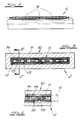
- the plastic hollow profile 4 is provided with an elongated, rectangular cross section and is constructed as a multi-cell profile. In the exemplary embodiment, four cells 6 are provided.
- the plastic hollow profile 4 has profile outer walls 7 and cell-forming webs 8. It is shaped in a corresponding extrusion tool in the tool head 1 and, during and / or afterwards, has been calibrated by internal cooling of the profile outer walls 7 and the cell-forming webs 8. The calibration achieved is an external calibration, although it is caused by an internal cooling.
- the plastic hollow profile 4 was provided with a shape stability by this internal cooling, which is stable up to a predetermined critical pressure, even at the deformation temperature.
- the calibrated and dimensionally adjusted multicellular hollow plastic profile 4 has been heated again at the contact surfaces 9 to the welding temperature of the thermoplastic, for example by irradiating the corresponding contact surfaces 9 with infrared rays, as indicated by the arrows in FIG. 2.
- the butt seam 5 between the turns is welded with an axial pressure below the critical pressure of the structural strength, as indicated by the arrows in FIG. 4.
- the axial pressure indicated by the arrows is generally about 10 to 15 percent less than the critical pressure of the set structural strength.
- the internal cooling takes place with a cooled coolant, e.g. B. water or oil.
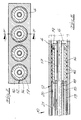
- the extrusion tool 10 has an outer tool 11 and an inner tool 12.
- the inner tool 12 is provided with cell-forming spikes 13. These are hollow arbors.
- the cell-forming mandrels 13 and / or cooling components 14 connected thereto are designed to be coolable.
- a cooling tube extends into the entire length of the cell-forming mandrels 13 or the connected cooling components 14, but in such a way that the cooling liquid supplied via a cooling tube 15 can escape from the cooling tube 15. It is deflected at the end of the cell-forming mandrels 13 or cooling components 14 and flows back, surrounding the cooling tube 15.
- the cooling tube 15 can be heat-insulated. Otherwise, the flow path of the cooling liquid could also be reversed.
- FIG. 5 shows a section of the outer tool 11. This, too, could be cooled. - The measures described are particularly suitable for the production of large-caliber plastic pipes of the construction described from polyvinyl chloride.
- FIGS. 7 and 8 The construction of another extrusion tool 10 for carrying out the method according to the invention results from FIGS. 7 and 8.
- This extrusion tool 10 also consists of an outer tool 11 and an inner tool 12, the inner tool 12 having cell-forming mandrels 13.
- a comparison of FIGS. 1 and 8 shows that in the embodiment according to FIGS. 7 and 8 the cell-forming mandrels 13 and cooling components 14 connected to them also extend into an area which is no longer surrounded by the external tool 11.
- the cooling components 14 adapted to the individual spikes are connected to the spikes 13. These have spaced-apart ribs 16 in the form of rings or Screw spirals.
- a return pipe 17 for a coolant is arranged in each case in the axis of the mandrels 13 and the cooling components 14.
- the coolant can be any cooled liquid, in particular also water or oil.
- the coolant can be supplied via an annular space 18 between the return pipe 17 and the cooling component outer wall.
- a coolant supply pipe 15 surrounding the return pipe 17 in the mandrels 13 connects to the annular space 18.
- the coolant exits at the end of the cooling components 14 via bores 19 in the area of the ribs 16 already mentioned.
- the mandrels 13 have suction bores 20 for the coolant at least in the region of the mandrel ends.
- the suction bores 20 open into a suction ring space 21 which surrounds the respective coolant supply pipe 15.
- the design is otherwise made such that a partial flow of the coolant flows out of the cooling components 14 in the extrusion direction into the cells 6, as is indicated in FIG. 8 by arrows, which on the one hand point in this outflow direction and on the other hand to the suction bores 20.
- the coolant can be removed via the respectively assigned return pipe 17.
- the cells 6 of the hollow plastic profiles 4 While in the embodiment according to FIGS. 2 to 6 the cells 6 of the hollow plastic profiles 4 have a rectangular cross section on the inside, it can be seen from FIG. 7 that the cells 6 of the hollow plastic profiles 4 have a round cross section on the inside.
- This embodiment of the extrusion tool is particularly suitable for the production of large-caliber plastic pipes made of polyethylene.
- the plastic hollow profiles 4 are first extruded as usual and undergo calibration mainly in the area outside the outer tool 11 on the mandrels 13. The calibration continues on the cooling components 14, which, however, are mainly used for cooling. The coolant flowing out through the suction ring spaces 21 is already warmed compared to the coolant emerging from the cooling components 14, which supports the calibration.
Landscapes
- Engineering & Computer Science (AREA)
- Mechanical Engineering (AREA)
- Physics & Mathematics (AREA)
- Thermal Sciences (AREA)
- Extrusion Moulding Of Plastics Or The Like (AREA)
- Shaping Of Tube Ends By Bending Or Straightening (AREA)
- Processing And Handling Of Plastics And Other Materials For Molding In General (AREA)
- Ultra Sonic Daignosis Equipment (AREA)
- Medicines Containing Antibodies Or Antigens For Use As Internal Diagnostic Agents (AREA)
- Extrusion Of Metal (AREA)
Abstract
Description
- Die Erfindung betrifft ein Verfahren zur Herstellung eines großkalibrlgen Kunststoffrohres, wobei ein Kunststoffhohlprofil aus thermoplastischem Kunststoff, welches einen rechteckigen Querschnitt aufweist, stranggepreßt (extrudiert) sowie das Kunststoffhohlprofil auf einer Trommel mit dicht an dicht liegenden Windungen bei ausreichender Verformungsfähigkeit schraubenwendelförmig gewickelt wird und wobei die Windungen beim Wickelvorgang an den Berührungsflächen miteinander mittels Stumpfnaht unter Anwendung von Axialdruck und Wärme verschweißt werden. - Der Kunststoff, aus dem das Kunststoffhohlprofil hergestellt wird, kann grundsätzlich ein beliebiger, für die Herstellung von Rohren geeigneter thermoplastischer Kunststoff sein. Insbesondere kann der Kunststoff der Gruppe der Polyolefine wie PE, PP etc. angehören. Der Kunststoff kann eine integrierte Bewehrung aus Fasern aufweisen und mit feinteiligen Füllern, insbesondere mineralischen Füllern versehen sein.
- Bei dem Verfahren, von dem die Erfindung ausgeht (DE-AS 23 08 418), ist das Kunststoffhohlprofil ein einzelliges Profil mit quadratischem oder rechteckigem Außenquerschnitt. Das Kunststoffhohlprofil wird mit im wesentlichen runden Innenquerschnitt extrudiert. In dieses Kunststoffhohlprofil wird bei der Extrusion eine Kühlflüssigkeit eingeleitet. Die Kühlflüssigkeit wird über zumindest eine Windung geführt. Die Windungen werden mit den Berührungswänden des Kunststoffhohlprofils dicht an dicht aneinanderliegend bei ausreichender Temperatur und unter dem Einfluß eines ausreichenden Axialdruckes verschweißt.
- Die bekannten Maßnahmen gehen von der Konzeption aus, daß bei der Herstellung von Rohren und insbesondere großkalibrigen Rohren aus Kunststoffhohlprofilen auf Flansche mit Überlappungsschweißnähten oder Formschluß verzichtet werden kann. Die bekannten Maßnahmen nützen die Tatsache aus, daß ein Kunststoffhohlprofil, welches sich auf Verformungstemperatur befindet, ohne weiteres mit dicht an dicht nebeneinanderliegenden Windungen gewickelt werden kann. Im Anschluß daran werden axiale Drücke, die für das Verschweißen der nebeneinanderliegenden Berührungswände erforderlich sind, vorzugsweise kinematisch erzeugt. Gleichzeitig wirkt ein durch die Einführung der Kühlflüssigkeit erzeugter Stützkern in dem Kunststoffhohlprofil gleichsam als Widerlager. Das erlaubt in axialer Richtung eine hinreichende Kompression und Stauchung für eine einwandfreie flächige Verschweißung der nebeneinanderliegenden Berührungswände des schraubenwendelförmig gewickelten Kunststoffhohlprofils. Man kann im Rahmen der bekannten Maßnahmen die Verhältnisse so einstellen, daß der Axialdruck eine bleibende Verformung bewirkt und den Querschnitt des Kunststoffhohlprofils beim Schweißen verändert. Ob das eine oder das andere eintritt, hängt von der Einstellung des axialen Druckes, d. h. der Stauchung, und von der Einstellung der Temperaturverhältnisse, aber auch von der Einstellung der Kühlung ab. Es versteht sich, daß das fertige Rohr von dem Wickeldorn, der auch als Trommel bezeichnet wird, abgezogen wird. - Die bekannten Maßnahmen haben sich bewährt, führen jedoch zu Kunststoffrohren mit für eine vorgegebene aufzunehmende Beanspruchung verhältnismäßig großem Gewicht. Sie lassen sich nur mit Kunststoffhohlprofilen herstellen, deren rechteckige Querschnittsform von der quadratischen Querschnittsform nur wenig entfernt ist.
- Demgegenüber liegt der Erfindung die Aufgabe zugrunde, ein Verfahren anzugeben, welches es erlaubt, Kunststoffrohre des beschriebenen Aufbaus mit reduziertem Gewicht; die nichtsdestoweniger die vorgegebenen Beanspruchungen ohne weiteres aufzunehmen in der Lage sind, herzustellen.
- Zur Lösung dieser Aufgabe lehrt die Erfindung, daß das Kunststoffhohlprofil mit langgestrecktem, rechteckigen Gesamtquerschnitt als Mehrzellenprofil mit Profilaußenwänden und zellenbildenden Stegen in einem Strangpreßwerkzeug geformt sowie dabei und/oder danach durch eine Innenkühlung der Profilaußenwände und der zellenbildenden Stege kalibriert und mit einer Gestaltfestigkeit versehen wird, die bis zu einem vorgegebenen kritischen Druck stabil ist, daß das kalibrierte und gestaltfest eingestellte Mehrzellenprofil an den Berührungsflächen wieder auf Schweißtemperatur des thermoplastischen Kunststoffes erwärmt wird, und daß die Stumpfnaht zwischen den Windungen mit einem unterhalb des kritischen Druckes der Gestaltfestigkeit liegenden Axialdruck geschweißt wird. Die Erfindung geht von der Erwägung aus, daß eine beachtliche Gewichtsreduzierung ohne Beeinträchtigung der Beanspruchbarkeit möglich ist, wenn mit einem Kunststoffhohlprofil gearbeitet wird, welches einen langgestreckten rechteckigen Querschnitt und in diesem eine Mehrzahl von ebenfalls rechteckigen Zellen aufweist, die durch zellenbildende Stege voneinander getrennt sind. Dabei können die Profilaußenwand und die zellenbildenden Stege mit verhältnismäßig geringer Wanddicke ausgebildet werden, was eine beachtliche Gewichtsersparnis ermöglicht. Ein solches Kunststoffhohlprofil kann- jedoch nicht in der eingangs beschriebenen bekannten Weise zum Rohr gewickelt und windungsweise unter Anwendung von Axialdruck verschweißt werden. Ohne weiteres würde es bei der erforderlichen Verformungstemperatur und unter dem Einfluß des für das Verschweißen erforderlichen Axialdruckes nach außen ausknicken. Die Erfindung verhindert dieses durch die Innenkühlung sowie die dadurch erreichte Stabilisierung und Einstellung der Gestaltfestigkeit. Im übrigen kann ein solches langgestrecktes mehrzelliges Kunststoffhohlprofil nicht ohne Kalibrierung eingesetzt werden, weil die Profilaußenwände im Bereich der Zellen einfallen würden. Das stört in optischer Hinsicht und beeinträchtigt darüber hinaus das Flächenträgheitsmoment des Kunststoffhohlprofils und damit die Ringsteifigkeit und Stabilität des gesamten Rohres. Grundsätzlich ist es bekannt, eine Kalibrierung eines auch mehrzelligen Kunststoffhohlprofils durchzuführen, und zwar als sogenannte Vakuumkalibrierung. Die Vakuumkalibrierung kann jedoch in das eingangs beschriebene Verfahren, von dem die Erfindung ausgeht und welches die Erfindung fortführt, nicht ohne weiteres integriert werden. Die Erfindung geht von der Erkenntnis aus, daß durch eine ausreichende Innenkühlung der Außenwände und der zellenbildenden Stege das mehrzellige Kunststoffhohlprofil gleichzeitig außen kalibriert und mit einer solchen Gestaltfestigkeit (im Sinne der klassischen technischen Mechanik) versehen werden kann, daß es die zur Herstellung der Stumpfschweißnaht zwischen den benachbarten Windungen erforderliche axiale Pressung ohne Gefahr des Ausknickens aufnehmen kann. Das gelingt, wenn der Axialdruck nicht zu hoch sein muß. Letzteres läßt sich durch die Beheizung der Berührungsflächen erreichen. Die Stumpfnaht zwischen den Windungen kann stets mit einem unterhalb des kritischen Druckes der Gestaltfestigkeit liegenden Axialdruck geschweißt werden. Die Länge des rechteckigen Querschnittes kann um einen Faktor 1 bis 5 oder sogar mehr größer sein als die Höhe oder Dicke des rechteckigen Gesamtquerschnitts des Kunststoffhohlprofils. Das Kunststoffhohlprofil kann eine Vielzahl von Zellen aufweisen.
- Im einzelnen bestehen im Rahmen der Erfindung mehrere Möglichkeiten der weiteren Ausbildung und Gestaltung. Im allgemeinen wird man die Innenkühlung durch gekühlte Bauteile des Strangpreßwerkzeuges und/oder durch daran angeschlossene Kühlbauteile bewirken. Die Kalibrierung sowie die Gestaltfestigkeit werden durch den Temperaturgradienten bei der Kühlung und durch die Kühlzeit eingestellt. Nach bevorzugter Ausführungsform erfolgt die Kühlung mit einer gekühlten Flüssigkeit vorgegebener Kühltemperatur. Überraschenderweise erreicht die Erfindung durch die Innenkühlung auch eine sehr genaue Außenkalibrierung des Kunststoffhohlprofils, wenn in der beschriebenen Weise gearbeitet und eine ausreichende Gestaltfestigkeit eingerichtet wird. Nichtsdestoweniger kann im Rahmen der Erfindung zusätzlich eine Außenkühlung verwirklicht und damit oder durch Kalibrierwerkzeuge die Außenkalibrierung verbessert werden.
- Gegenstand der Erfindung sind auch Strangpreßwerkzeuge für die Durchführung des beschriebenen Verfahrens, wie sie einerseits Gegenstand der Patentansprüche 5 und 6 und andererseits der Patentansprüche 7 und 8 sind.
- Im folgenden wird die Erfindung anhand einer lediglich ein Ausführungsbeispiel darstellenden Zeichnung ausführlicher erläutert. Es zeigen in schematischer Darstellung
- Fig. 1 die Seitenansicht einer Anlage, die für das erfindungsgemäße Verfahren eingerichtet ist ,
- Fig. 2 in gegenüber der Fig. 1 wesentlich vergrößertem Maßstab einen Schnitt in Richtung A-A durch den Gegenstand nach Fig. 1,
- Fig. 3 in nochmaliger Vergrößerung den Ausschnitt B aus dem Gegenstand nach Fig. 2,
- Fig. 4 in gegenüber der Fig. 1 vergrößertem Maßstab einen Schnitt in Richtung C-C durch den Gegenstand nach Fig. 1, ausschnittsweise,
- Fig. 5 im Maßstab der Fig. 2 einen Schnitt in Richtung D-D durch den Gegenstand nach Fig. 1,
- Fig. 6 einen Schnitt in Richtung E-E durch den Gegenstand nach Fig. 5,
- Fig. 7 entsprechend der Fig. 2 einen Schnitt durch eine andere Ausführungsform des Gegenstandes der Fig. 1, und
- Fig. 8 einen Schnitt in Richtung F-F durch den Gegenstand der Fig. 7
- In der Fig. 1 erkennt man den Werkzeugkopf 1 einer Kunststoffschnekkenpresse (eines Extruders), an den sich ein Kühlfortsatz 2 anschließt. Man erkennt rechts eine rotierende Trommel 3, die auch als Wickeldorn bezeichnet werden könnte. Im einzelnen mag diese Anlage im übrigen in weitgehender Übereinstimmung mit den eingangs beschriebenen bekannten Maßnahmen aufgebaut sein (DE-AS 23 08 418). Vergleicht man die Fig. 1 und 4, so erkennt man, daß ein Kunststoffhohlprofil 4 aus thermoplastischem Kunststoff, welches einen rechteckigen Querschnitt aufweist, stran gepreßt und auf der Trommel 3 mit dicht an dicht liegenden Windungen bei ausreichender Verformungsfähigkeit gewickelt wird. Die Windungen werden beim Wickelvorgang an den Berührungsflächen miteinander mittels Stumpfnaht 5 unter Anwendung von Axialdruck und Wärme verschweißt.
- Insbesondere aus der Fig. 2 erkennt man, daß das Kunststoffhohlprofil 4 mit einem langgestreckten, rechteckigen Querschnitt versehen und als Mehrzellenprofil aufgebaut ist. Im Ausführungsbeispiel sind vier Zellen 6 vorgesehen. Das Kunststoffhohlprofil 4 besitzt Profilaußenwände 7 und zellenbildende Stege 8. Es ist in einem entsprechenden Strangpreßwerkzeug im Werkzeugkopf 1 geformt sowie dabei und/oder danach durch eine Innenkühlung der Profilaußenwände 7 und der zellenbildenden Stege 8 kalibriert worden. Die erreichte Kalibrierung ist eine Außenkalibrierung, obgleich sie durch eine Innenkühlung bewirkt wird. Gleichzeitig wurde jedoch das Kunststoffhohlprofil 4 durch diese Innenkühlung mit einer Gestaltfestigkeit versehen, die bis zu einem vorgegebenen kritischen Druck stabil ist, und zwar auch bei Verformungstemperatur. In der Fig. 3 wurde durch die Doppelschraffur angedeutet, daß durch die Innenkühlung im statischen Sinne gleichsam eine Schalenbildung erreicht wird und im Ergebnis ein Kastentragwerk entstanden ist, welches die beschriebene Gestaltfestigkeit besitzt. Das kalibrierte und gestaltfest eingestellte mehrzellige Kunststoffhohlprofil 4 ist an den Berührungsflächen 9 wieder auf die Schweißtemperatur des thermoplastischen Kunststoffes erwärmt worden, beispielsweise durch eine Bestrahlung der entsprechenden Berührungsflächen 9 mit Infrarotstrahlen, wie es in der Fig. 2 durch geweilte Pfeile angedeutet wurde. Die Stumpfnaht 5 zwischen den Windungen wird mit einem unterhalb des kritischen Druckes der Gestaltfestigkeit liegenden Axialdruck geschweißt, wie es die Pfeile in der Fig. 4 andeuten. Der durch die Pfeile angedeutete Axialdruck ist im allgemeinen um etwa 10 bis 15 Prozent kleiner als es dem kritischen Druck der eingestellten Gestaltfestigkeit entspricht. Die Innenkühlung erfolgt mit einer gekühlten Kühlflüssigkeit, z. B. Wasser oder Öl.
- Die Fig. 5 und 6 erläutern Einzelheiten zu einem Strangpreßwerkzeug 10, welches für die Durchführung des erfindungsgemäßen Verfahrens besonders eingerichtet und in dem Werkzeugkopf 1 angeordnet ist. Das Strangpreßwerkzeug 10 besitzt ein Außenwerkzeug 11 und ein Innenwerkzeug 12. Das Innenwerkzeug 12 ist mit zellenbildenden Dornen 13 versehen. Diese sind Hohldorne. Die zellenbildenden Dorne 13 und/oder daran angeschlossene Kühlbauteile 14 sind kühlbar ausgeführt. Dazu reicht ein Kühlrohr in die gesamte Länge der zellenbildenden Dorne 13 bzw. der angeschlossenen Kühlbauteile 14 hinein, jedoch so, daß die über ein Hühlrohr 15 zugeführte Kühlflüssigkeit aus dem Kühlrohr 15 austreten kann. Sie wird am Abschlußende der zellenbildenden Dorne 13 oder Kühlbauteile 14 umgelenkt und strömt, das Kühlrohr 15 außen umgebend, zurück. Das Kühlrohr 15 kann wärmeisoliert ausgeführt sein. Im übrigen könnte der Strömungsweg der Kühlflüssigkeit auch umgekehrt werden In der Fig. 5 erkennt man ein Teilstück des Außenwerkzeuges 11. Auch dieses könnte gekühlt sein. - Die beschriebenen Maßnahmen eignen sich insbesondere für die Herstellung von großkalibrigen Kunststoffrohren des beschriebenen Aufbaus aus Polyvinylchlorid.
- Der Aufbau eines anderen Strangpreßwerkzeuges 10 für die Durchführung des erfindungsgemäßen Verfahrens ergibt sich aus den Fig. 7 und 8. Auch dieses Strangpreßwerkzeug 10 besteht aus einem Außenwerkzeug 11 und aus einem Innenwerkzeug 12, wobei das Innenwerkzeug 12 zellenbildende Dorne 13 aufweist. Aus einer vergleichenden Betrachtung der Fig. 1 und 8 ergibt sich, daß bei der Ausführungsform nach den Fig. 7 und 8 die zellenbildenden Dorne 13 und daran angeschlossene Kühlbauteile 14 sich auch in einen Bereich hineinerstrecken, der von dem Außenwerkzeug 11 nicht mehr umgeben ist. An die Dorne 13 sind die den einzelnen Dornen angepaßte Kühlbauteile 14 angeschlossen. Diese besitzen mit Abstand voneinander umlaufende Rippen 16 in Form von Ringen oder Schraubenwendeln. In der Achse der Dorne 13 und der Kühlbauteile 14 ist jeweils ein Rückführungsrohr 17 für ein Kühlmittel angeordnet. Das Kühlmittel kann, wie beschrieben, Jede gekühlte Flüssigkeit sein, insbesondere auch Wasser oder Öl. Das Kühlmittel ist über einen Ringraum 18 zwischen Rückführungsrohr 17 und Kühlbauteilaußenwand zuführbar. An den Ringraum 18 schließt ein das Rückführungsrohr 17 in den Dornen 13 umgebendes Kühlmittelzuführungsrohr 15 an. Das Kühlmittel tritt am Ende der Kühlbauteile 14 über Bohrungen 19 in den Bereich der schon erwähnten Rippen 16 aus. Die Dorne 13 besitzen Absaugbohrungen 20 für das Kühlmittel zumindest im Bereich der Dornenden. Die Absaugbohrungen 20 münden in einen Absaugringraum 21 ein, der das jeweilige Kühlmittelzuführungsrohr 15 umgibt. Die Auslegung ist im übrigen so getroffen, daß ein Teilstrom des Kühlmittels an den Kühlbauteilen 14 in Extrusionsrichtung in die Zellen 6 abströmt, wie es in der Fig. 8 durch Pfeile angedeutet ist, die einerseits in diese Abströmrichtung und andererseits zu den Absaugbohrungen 20 hinweisen. Über das jeweils zugeordnete Rückführungsrohr 17 ist das Kühlmittel abführbar.
- Während bei der Ausführungsform nach den Fig. 2 bis 6 die Zellen 6 der Kunststoffhohlprofile 4 innenseitig einen rechteckigen Querschnitt aufweisen, entnimmt man aus der Fig. 7, daß hier die Zellen 6 der Kunststoffhohlprofile 4 innen einen runden Querschnitt aufweisen. Diese Ausführungsform des Strangpreßwerkzeuges eignet sich insbesondere für die Herstellung von großkalibrigen Kunststoffrohren aus Polyäthylen. Die Kunststoffhohlprofile 4 werden zunächst wie üblich extrudiert und erfahren eine Kalibrierung hauptsächlich im Bereich außerhalb des Außenwerkzeuges 11 auf den Dornen 13. Die Kalibrierung setzt sich auf den Kühlbauteilen 14 fort, die jedoch hauptsächlich der Kühlung dienen. Das über die Absaugringräume 21 abströmende Kühlmittel ist gegenüber dem aus den Kühlbauteilen 14 austretenden Kühlmittel bereits erwärmt, was die Kalibrierung unterstützt.
Claims (8)
wobei ein Kunststoffhohlprofil aus thermoplastischem Kunststoff, welches einen rechteckigen Querschnitt aufweist, stranggepreßt (extrudiert) sowie das Kunststoffhohlprofil auf einer Trommel mit dicht an dicht liegenden Windungen bei ausreichender Verformungsfähigkeit schraubenwendelförmig gewickelt wird und wobei die Windungen beim Wickelvorgang an den Berührungsflächen miteinander mittels Stumpfnaht unter Anwendung von Axialdruck und Wärme verschweißt werden,
dadurch gekennzeichnet, daß das Kunststoffhohlprofil mit langgestrecktem, rechteckigen Gesamtquerschnitt als Mehrzellenprofil mit Profilaußenwänden und zellenbildenden Stegen in einem Strangpreßwerkzeug geformt sowie dabei und/oder danach durch eine Innenkühlung der Profilaußenwände und der zellenbildenden Stege kalibriert und mit einer Gestaltfestigkeit versehen wird, die bis zu einem vorgegebenen kritischen Druck stabil ist,
daß das kalibrierte und gestaltfest eingestellte Mehrzellenprofil an den Berührungsflächen wieder auf Schweißtemperatur des thermoplastischen Kunststoffes erwärmt wird,
und daß die Stumpfnaht zwischen den Windungen mit einem unterhalb des kritischen Druckes der Gestaltfestigkeit liegenden Axialdruck geschweißt wird.
Außenwerkzeug und Innenwerkzeug,
wobei das Innenwerkzeug zellenbildende Dorne aufweist, dadurch gekennzeichnet, daß die zellenbildenden Dorne (13) und/oder daran angeschlossene, dem Zellenquerschnitt angepaßte Kühlbauteile (14) kühlbar ausgeführt sind.
Außenwerkzeug und Innenwerkzeug,
wobei das Innenwerkzeug zellenbildende Dorne aufweist, dadurch gekennzeichnet, daß an die Dorne (13) den einzelnen Dornen (13) angepaßte Kühlbauteile (14) angeschlossen sind, die mit Abstand voneinander umlaufende Rippen (16) in Form von Ringen oder Schraubenwendeln aufweisen, daß in der Achse der Dorne (13) und der Kühlbauteile (14) ein Rückführungsrohr (17) für ein Kühlmittel angeordnet und das Kühlmittel über einen Ringraum zwischen Rückführungsrohr (17) und Kühlbauteilaußenwand zuführbar ist, an welchen Ringraum ein das Rückführungsrohr (17) in den Dornen (13) umgebendes Kühlmittelzuführungsrohr (15) anschließt, wobei das Kühlmittel am Ende der Kühlbauteile (14) über Bohrungen (19) in den Bereich der Rippen (16) austritt, daß die Dorne (13) Absaugbohrungen (20) für das Kühlmittel zumindest im Bereich der Dornenden aufweisen, die in einen Absaugringraum (21) einmünden, der das jeweilige Kühlmittelzuführungsrohr (15) umgibt, und daß ein Teilstrom des Kühlmittels in den Kühlbauteilen (14) in Extrusionsrichtung in die Zellen (6) abströmt und über das jeweils zugeordnete Rückführungsrohr (17) abführbar ist.
Applications Claiming Priority (2)
| Application Number | Priority Date | Filing Date | Title |
|---|---|---|---|
| DE3931614A DE3931614A1 (de) | 1989-09-22 | 1989-09-22 | Verfahren zur herstellung eines grosskalibrigen kunststoffrohres und strangpresswerkzeug fuer die durchfuehrung des verfahrens |
| DE3931614 | 1989-09-22 |
Publications (3)
| Publication Number | Publication Date |
|---|---|
| EP0418760A2 true EP0418760A2 (de) | 1991-03-27 |
| EP0418760A3 EP0418760A3 (en) | 1991-11-13 |
| EP0418760B1 EP0418760B1 (de) | 1995-12-20 |
Family
ID=6389949
Family Applications (1)
| Application Number | Title | Priority Date | Filing Date |
|---|---|---|---|
| EP90117778A Expired - Lifetime EP0418760B1 (de) | 1989-09-22 | 1990-09-15 | Verfahren zur Herstellung eines grosskalibrigen Kunststoffrohres und Strangpresswerkzeug für die Durchführung des Verfahrens |
Country Status (13)
| Country | Link |
|---|---|
| EP (1) | EP0418760B1 (de) |
| JP (1) | JPH03205137A (de) |
| AT (1) | ATE131770T1 (de) |
| AU (1) | AU633362B2 (de) |
| CA (1) | CA2025995C (de) |
| DE (1) | DE3931614A1 (de) |
| ES (1) | ES2080773T3 (de) |
| FI (1) | FI904665A7 (de) |
| GR (1) | GR3019367T3 (de) |
| NO (1) | NO904089L (de) |
| PT (1) | PT95370B (de) |
| RU (1) | RU1823818C (de) |
| ZA (1) | ZA907575B (de) |
Cited By (6)
| Publication number | Priority date | Publication date | Assignee | Title |
|---|---|---|---|---|
| EP0515906A3 (en) * | 1991-05-27 | 1993-01-27 | Schueco International Kg | Method and device for producing rope formed hollow profiles from thermoplastic material |
| WO1993022126A1 (en) * | 1992-04-30 | 1993-11-11 | Oy Kwh Pipe Ab | A welding method in the manufacture of a spirally wound tube and a welding head for performing the method |
| EP0698471A1 (de) * | 1994-08-12 | 1996-02-28 | Heinz Grösswang | Strangpresswerkzeugkopf |
| US5924456A (en) * | 1993-07-01 | 1999-07-20 | Hutchinson | Tubular section member, in particular for use as a fluid flow duct |
| US6105649A (en) * | 1998-09-30 | 2000-08-22 | Jerry C. Levingston | Pipe extrusion apparatus including winding a hollow profile |
| CN113954329A (zh) * | 2021-11-10 | 2022-01-21 | 重庆金山洋生管道有限公司 | 大口径加筋管加工设备 |
Families Citing this family (5)
| Publication number | Priority date | Publication date | Assignee | Title |
|---|---|---|---|---|
| DE19806424A1 (de) * | 1998-02-17 | 1999-08-19 | Hdw Isoliertechnik Gmbh | Verfahren zur Herstellung von Wabenmaterial und Wabenmaterial für Transparente Wärmedämmung |
| DE102008063478A1 (de) | 2008-12-17 | 2010-07-08 | Audi Ag | Vorrichtung zur Abkühlung von Hohlprofilbauteilen |
| FI124400B (en) * | 2012-11-20 | 2014-08-15 | Uponor Infra Oy | Method and apparatus for making spirally wound and welded pipe |
| UA115587C2 (uk) | 2015-10-09 | 2017-11-27 | Олександр Миколайович Березін | Спіральношовний полімерний виріб із стільниковою стінкою (варіанти) та довгомірний порожнистий термопластичний профіль для його виробництва |
| JP6911067B2 (ja) * | 2019-02-19 | 2021-07-28 | タキロンシーアイシビル株式会社 | 継手構造、液輸送管、および、液輸送管の接続方法 |
Family Cites Families (10)
| Publication number | Priority date | Publication date | Assignee | Title |
|---|---|---|---|---|
| FR1131433A (fr) * | 1953-12-30 | 1957-02-21 | Matières en feuilles, procédés et machines pour leur fabrication | |
| IL22357A (en) * | 1963-11-22 | 1968-04-25 | Petzetakis Aristovoulos George | Calibration of tubes |
| US3443593A (en) * | 1967-07-24 | 1969-05-13 | Mount Hope Machinery Ltd | Hydrodynamically balanced rotary valve |
| US3825641A (en) * | 1971-06-04 | 1974-07-23 | L Barnett | Method of forming multiple passageway plastic conduit |
| DE2308418B2 (de) * | 1972-06-21 | 1976-04-08 | Petzetakis, Aristovoulos George, Moschaton, Piräus (Griechenland) | Verfahren und vorrichtung zum herstellen eines insbesondere grosskalibrigen rohres aus thermoplastischem kunststoff |
| DE2506517C3 (de) * | 1975-02-15 | 1978-03-30 | Barmag Barmer Maschinenfabrik Ag, 5630 Remscheid | Vorrichtung zur Flüssigkeits-Innenkühlung von stranggepreßten Rohren oder Schläuchen |
| DE2613385C2 (de) * | 1976-03-29 | 1977-11-03 | Siemens AG, 1000 Berlin und 8000 München | HF-Prüfeinrichtung für installierte Koaxial-Kabelstrecken |
| DE2613386A1 (de) * | 1976-03-29 | 1977-10-13 | Gideon Gilead | Verfahren zur herstellung eines kunststoffrohres |
| DE8704071U1 (de) * | 1987-03-19 | 1987-04-30 | M. Stükerjürgen Kunststoffwerk GmbH & Co KG, 4835 Rietberg | Band zum wendelförmigen Wickeln von Rohren |
| DE8803551U1 (de) * | 1988-03-16 | 1988-05-26 | RKM Rose Kabelmontage GmbH & Co KG, 6108 Weiterstadt | Vorrichtung zur Wanddurchführung |
-
1989
- 1989-09-22 DE DE3931614A patent/DE3931614A1/de active Granted
-
1990
- 1990-09-15 AT AT90117778T patent/ATE131770T1/de not_active IP Right Cessation
- 1990-09-15 ES ES90117778T patent/ES2080773T3/es not_active Expired - Lifetime
- 1990-09-15 EP EP90117778A patent/EP0418760B1/de not_active Expired - Lifetime
- 1990-09-19 NO NO90904089A patent/NO904089L/no unknown
- 1990-09-20 AU AU63003/90A patent/AU633362B2/en not_active Expired
- 1990-09-20 PT PT95370A patent/PT95370B/pt not_active IP Right Cessation
- 1990-09-21 CA CA002025995A patent/CA2025995C/en not_active Expired - Lifetime
- 1990-09-21 JP JP2250412A patent/JPH03205137A/ja active Pending
- 1990-09-21 ZA ZA907575A patent/ZA907575B/xx unknown
- 1990-09-21 FI FI904665A patent/FI904665A7/fi not_active IP Right Cessation
- 1990-09-21 RU SU904831213A patent/RU1823818C/ru active
-
1996
- 1996-03-20 GR GR960400766T patent/GR3019367T3/el unknown
Cited By (9)
| Publication number | Priority date | Publication date | Assignee | Title |
|---|---|---|---|---|
| EP0515906A3 (en) * | 1991-05-27 | 1993-01-27 | Schueco International Kg | Method and device for producing rope formed hollow profiles from thermoplastic material |
| WO1993022126A1 (en) * | 1992-04-30 | 1993-11-11 | Oy Kwh Pipe Ab | A welding method in the manufacture of a spirally wound tube and a welding head for performing the method |
| US5591292A (en) * | 1992-04-30 | 1997-01-07 | Oy Kwh Pipe Ab | Welding method in the manufacture of a spirally wound tube and a welding head for performing the method |
| US5924456A (en) * | 1993-07-01 | 1999-07-20 | Hutchinson | Tubular section member, in particular for use as a fluid flow duct |
| EP0698471A1 (de) * | 1994-08-12 | 1996-02-28 | Heinz Grösswang | Strangpresswerkzeugkopf |
| US6105649A (en) * | 1998-09-30 | 2000-08-22 | Jerry C. Levingston | Pipe extrusion apparatus including winding a hollow profile |
| US6488802B1 (en) | 1998-09-30 | 2002-12-03 | Jerry C. Levingston | Pipe extrusion process |
| CN113954329A (zh) * | 2021-11-10 | 2022-01-21 | 重庆金山洋生管道有限公司 | 大口径加筋管加工设备 |
| CN113954329B (zh) * | 2021-11-10 | 2023-12-15 | 重庆金山洋生管道有限公司 | 大口径加筋管加工设备 |
Also Published As
| Publication number | Publication date |
|---|---|
| FI904665A0 (fi) | 1990-09-21 |
| NO904089L (no) | 1991-03-25 |
| FI904665A7 (fi) | 1991-03-23 |
| PT95370B (pt) | 1997-06-30 |
| EP0418760A3 (en) | 1991-11-13 |
| AU633362B2 (en) | 1993-01-28 |
| ES2080773T3 (es) | 1996-02-16 |
| DE3931614C2 (de) | 1993-07-08 |
| CA2025995A1 (en) | 1991-03-23 |
| DE3931614A1 (de) | 1991-04-11 |
| CA2025995C (en) | 2001-01-16 |
| JPH03205137A (ja) | 1991-09-06 |
| EP0418760B1 (de) | 1995-12-20 |
| RU1823818C (ru) | 1993-06-23 |
| NO904089D0 (no) | 1990-09-19 |
| ZA907575B (en) | 1991-07-31 |
| GR3019367T3 (en) | 1996-06-30 |
| PT95370A (pt) | 1992-05-29 |
| ATE131770T1 (de) | 1996-01-15 |
| AU6300390A (en) | 1991-03-28 |
Similar Documents
| Publication | Publication Date | Title |
|---|---|---|
| DE2308418A1 (de) | Verfahren und anlage zur herstellung eines insbesondere grosskalibrigen rohres aus thermoplastischem kunststoff | |
| DE2510804C2 (de) | Vorrichtung zum Kühlen von Schlauchblasfolien aus thermoplastischem Kunststoff | |
| DE2159902C3 (de) | Verfahren und Vorrichtung zum Herstellen einer mehrschichtigen rohrförmigen Kunststoff-Tragstruktur | |
| DD255506A5 (de) | Verfahren und vorrichtung zur herstellung von rippenflanschrohren | |
| EP0418760B1 (de) | Verfahren zur Herstellung eines grosskalibrigen Kunststoffrohres und Strangpresswerkzeug für die Durchführung des Verfahrens | |
| EP0708729B1 (de) | Palettencontainer | |
| EP2992978B1 (de) | Matrizenmodulsatz für presswerkzeuge zum herstellen von schrauben | |
| DE202007019107U1 (de) | Wärmeisoliertes Leitungsrohr | |
| DE102015118163A1 (de) | Windenergieturm | |
| DE102010043786A1 (de) | Vorrichtung zur Herstellung von Rohren aus thermoplastischem Kunststoff | |
| DE60215390T2 (de) | Verfahren zur herstellung eines luftreifens und dabei verwendeter extruder | |
| DE19941160A1 (de) | Zylinder für einen Schneckenextruder mit Kanälen für ein Temperiermedium | |
| DE2911833C3 (de) | Gerader Spritzkopf zum Extrudieren zweier zueinander konzentrischer Kunststoffrohre | |
| DE10024625A1 (de) | Formnest für die Kunststoffverarbeitung | |
| DE2111349A1 (de) | Kernreaktorbrennelement | |
| DE29613795U1 (de) | Walze mit optimiertem Biegeverhalten | |
| EP0835745B1 (de) | Verfahren und Vorrichtung zum Herstellen von rohrförmigen Hohlkörpern | |
| DE4135336C2 (de) | Verfahren zum Strangpressen von Mehrschichtrohren | |
| WO2022090135A1 (de) | Formwerkzeug und verfahren zum strangpressen von metallischen werkstücken | |
| DE1088912B (de) | Ausgangsmaterial fuer die Herstellung schraubennahtgeschweisster Hohlkoerper, z. B. Rohre | |
| DE2106191C3 (de) | Rundflechtmaschine zum Umflechten eines Schlauchrohlings | |
| DE2345957A1 (de) | Verfahren und anordnung zur herstellung extrudierter kunststoffhohlprofile | |
| DE3404294C1 (de) | Rohrteil aus einem thermoplastischen Kunststoff | |
| DE4407060A1 (de) | Extrusionswerkzeug für Schlauchfolien | |
| DE1501597C (de) | Verfahren zur Herstellung eines Wärmeaustauscher-Rohrbündels aus flexiblen Rohren aus thermoplastischem Werkstoff |
Legal Events
| Date | Code | Title | Description |
|---|---|---|---|
| PUAI | Public reference made under article 153(3) epc to a published international application that has entered the european phase |
Free format text: ORIGINAL CODE: 0009012 |
|
| AK | Designated contracting states |
Kind code of ref document: A2 Designated state(s): AT BE CH DK ES FR GB GR IT LI NL SE |
|
| 17P | Request for examination filed |
Effective date: 19910406 |
|
| PUAL | Search report despatched |
Free format text: ORIGINAL CODE: 0009013 |
|
| AK | Designated contracting states |
Kind code of ref document: A3 Designated state(s): AT BE CH DK ES FR GB GR IT LI NL SE |
|
| 17Q | First examination report despatched |
Effective date: 19940328 |
|
| GRAA | (expected) grant |
Free format text: ORIGINAL CODE: 0009210 |
|
| AK | Designated contracting states |
Kind code of ref document: B1 Designated state(s): AT BE CH DK ES FR GB GR IT LI NL SE |
|
| PG25 | Lapsed in a contracting state [announced via postgrant information from national office to epo] |
Ref country code: DK Effective date: 19951220 Ref country code: GB Effective date: 19951220 Ref country code: BE Effective date: 19951220 |
|
| REF | Corresponds to: |
Ref document number: 131770 Country of ref document: AT Date of ref document: 19960115 Kind code of ref document: T |
|
| ITF | It: translation for a ep patent filed | ||
| REG | Reference to a national code |
Ref country code: ES Ref legal event code: FG2A Ref document number: 2080773 Country of ref document: ES Kind code of ref document: T3 |
|
| ET | Fr: translation filed | ||
| REG | Reference to a national code |
Ref country code: GR Ref legal event code: FG4A Free format text: 3019367 |
|
| GBV | Gb: ep patent (uk) treated as always having been void in accordance with gb section 77(7)/1977 [no translation filed] |
Effective date: 19951220 |
|
| PG25 | Lapsed in a contracting state [announced via postgrant information from national office to epo] |
Ref country code: AT Effective date: 19960915 |
|
| PG25 | Lapsed in a contracting state [announced via postgrant information from national office to epo] |
Ref country code: SE Effective date: 19960916 |
|
| PG25 | Lapsed in a contracting state [announced via postgrant information from national office to epo] |
Ref country code: CH Effective date: 19960930 Ref country code: LI Effective date: 19960930 |
|
| PLBE | No opposition filed within time limit |
Free format text: ORIGINAL CODE: 0009261 |
|
| STAA | Information on the status of an ep patent application or granted ep patent |
Free format text: STATUS: NO OPPOSITION FILED WITHIN TIME LIMIT |
|
| 26N | No opposition filed | ||
| PG25 | Lapsed in a contracting state [announced via postgrant information from national office to epo] |
Ref country code: NL Effective date: 19970401 |
|
| REG | Reference to a national code |
Ref country code: CH Ref legal event code: PL |
|
| NLV4 | Nl: lapsed or anulled due to non-payment of the annual fee |
Effective date: 19970401 |
|
| EUG | Se: european patent has lapsed |
Ref document number: 90117778.2 |
|
| PGFP | Annual fee paid to national office [announced via postgrant information from national office to epo] |
Ref country code: ES Payment date: 20090922 Year of fee payment: 20 |
|
| PGFP | Annual fee paid to national office [announced via postgrant information from national office to epo] |
Ref country code: IT Payment date: 20090926 Year of fee payment: 20 |
|
| PGFP | Annual fee paid to national office [announced via postgrant information from national office to epo] |
Ref country code: GR Payment date: 20090930 Year of fee payment: 20 |
|
| PGFP | Annual fee paid to national office [announced via postgrant information from national office to epo] |
Ref country code: FR Payment date: 20091001 Year of fee payment: 20 |
|
| REG | Reference to a national code |
Ref country code: ES Ref legal event code: FD2A Effective date: 20130718 |
|
| PG25 | Lapsed in a contracting state [announced via postgrant information from national office to epo] |
Ref country code: ES Free format text: LAPSE BECAUSE OF EXPIRATION OF PROTECTION Effective date: 20100916 |