EP0418763A1 - Servolenkeinrichtung - Google Patents
Servolenkeinrichtung Download PDFInfo
- Publication number
- EP0418763A1 EP0418763A1 EP90117785A EP90117785A EP0418763A1 EP 0418763 A1 EP0418763 A1 EP 0418763A1 EP 90117785 A EP90117785 A EP 90117785A EP 90117785 A EP90117785 A EP 90117785A EP 0418763 A1 EP0418763 A1 EP 0418763A1
- Authority
- EP
- European Patent Office
- Prior art keywords
- steering
- hydraulic
- steering apparatus
- power steering
- power
- Prior art date
- Legal status (The legal status is an assumption and is not a legal conclusion. Google has not performed a legal analysis and makes no representation as to the accuracy of the status listed.)
- Granted
Links
- 230000033001 locomotion Effects 0.000 claims abstract description 23
- 230000004044 response Effects 0.000 claims abstract description 13
- 230000009471 action Effects 0.000 claims abstract description 11
- 238000006243 chemical reaction Methods 0.000 claims description 18
- 230000000452 restraining effect Effects 0.000 claims 1
- 230000000875 corresponding effect Effects 0.000 description 23
- 230000007246 mechanism Effects 0.000 description 8
- 238000006073 displacement reaction Methods 0.000 description 6
- 230000003134 recirculating effect Effects 0.000 description 4
- 230000007423 decrease Effects 0.000 description 2
- 230000004323 axial length Effects 0.000 description 1
- 230000005540 biological transmission Effects 0.000 description 1
- 230000008859 change Effects 0.000 description 1
- 230000007547 defect Effects 0.000 description 1
- 229940086255 perform Drugs 0.000 description 1
- 238000007789 sealing Methods 0.000 description 1
Images


Classifications
-
- B—PERFORMING OPERATIONS; TRANSPORTING
- B62—LAND VEHICLES FOR TRAVELLING OTHERWISE THAN ON RAILS
- B62D—MOTOR VEHICLES; TRAILERS
- B62D5/00—Power-assisted or power-driven steering
-
- B—PERFORMING OPERATIONS; TRANSPORTING
- B62—LAND VEHICLES FOR TRAVELLING OTHERWISE THAN ON RAILS
- B62D—MOTOR VEHICLES; TRAILERS
- B62D6/00—Arrangements for automatically controlling steering depending on driving conditions sensed and responded to, e.g. control circuits
- B62D6/02—Arrangements for automatically controlling steering depending on driving conditions sensed and responded to, e.g. control circuits responsive only to vehicle speed
Definitions
- This invention relates to a hydraulic power steering apparatus using a hydraulic actuator as a steering assisting power source.
- a hydraulic power steering apparatus which assists by hydraulic pressure strength required for steering has hith necessarilyerto been widely used not only for a large-sized vehicle, such as a truck or a motorbus, but also for a small-sized vehicle, such as an ordinary passenger car.
- the power steering apparatus disposes a hydraulic actuator, such as a hydraulic cylinder, in a steering mechanism for converting rotation of a steering wheel into steering motion, and a hydraulic control valve for performing hydraulic charge control corresponding to operation of the steering wheel halfway of a hydraulic supply route to the hydraulic cylinder.
- the hydraulic cylinder generates steering assisting power by hydraulic pressure supplied through the hydraulic control valve, so that the steering assisting power assists steering motion, thereby reducing power to operate the steering wheel for steering the vehicle.
- a mode of disposing the hydraulic cylinder for steering assisting is different in a type of a steering mechanism.
- a steering mechanism of the so-called recirculating ball screw type which converts the rotation of steering wheel into axial movement of a ball nut screwable through a ball screw thread with a shaft connected to the steering wheel and rotation of a sector gear screwable with a rack axially extending outside the ball nut, and steers wheels of the vehicle through a proper link mechanism.
- the hydraulic cylinder for steering assisting at such steering mechanism often uses the ball nut as a piston. In this case, action of the hydraulic cylinder is converted into steering motion through operation converting means comprising the rack and sector gear.
- the manual force W r in the equation (1) in the vehicle provided with a steering mechanism of the recirculating ball screw type, is obtained by a steering torque T r applied to the steering wheel, a module m of the sector gear, the number Z of teeth of the sector gear, and a lead p of ball screw thread, and given in the following equation:
- the steering for an automobile is carried out against road reaction power acting on the wheels. Since the magnitude of the road reaction power corresponds to the vehicle speed, although a large total resultant force W is required for steering while stopping and running at low speed, a relatively small total resultant force W can perform steering while running at high speed. Accordingly, in the aforesaid power steering apparatus, a relatively large steering assisting power W s is required to be generated for reducing as much as possible the steering torque applied to the steering wheel in order to obtain the manual force W r . On the other hand, when an equivalent steering assisting power W s is generated during the high speed running, a small force applied to the steering wheel performs the steering, whereby a drawback is created in that the running safety is hindered. Hence, it is required to generate steering assisting power W s as small as possible during the high speed running.
- an oil passage connected to a low pressure source through a movable throttle and a fixed throttle is formed at the discharge side of a hydraulic pump for generating the constant pressure so as to change a degree of opening of the movable throttle corresponding to variation in the vehicle speed, whereby the hydraulic pressure introduced into the hydraulic reaction power unit and corresponding to the vehicle speed is obtainable between both the throttles.
- a vehicle speed sensor pump connected in associa tion with an output shaft of a transmission gear and driven at the speed corresponding to the vehicle speed.
- the steering assisting power W s generated by the hydraulic cylinder for steering assisting is given as shown in the equation (3), so that the charged hydraulic pressure P m to the hydraulic cylinder or the cylinder's area A can be increased to expect an increase in W s .
- the charged hydraulic pressure P m and cylinder's area A are set in consideration of generation of sufficient steering assisting power W s at a large steering angle, a large-sized hydraulic pump as a source for generating hydraulic pres sure, an increase in power consumption by the hydraulic pump and a large-sized apparatus as a whole, will be necessary. Accordingly, it is not said to be an actual remedy that P m or A is increased to ensure the steering assisting power W s at a large steering angle.
- the present invention has been designed.
- An object of the present invention is to provide a power steering apparatus which is capable of increasing with ease the steering assisting power generated by a hydraulic actuator as a steering angle increases.
- Another object of the present invention is to provide a power steering apparatus which can largely reduce a burden of labor for largely operating a steering wheel without increasing capacity of the hydraulic actuator.
- Still another object of the present invention is to provide a power steering apparatus which can generate a large steering assisting power without increasing a cylinder's area at a hydraulic cylinder for assisting a steering operation or charging a large hydraulic pressure when the steering angle is large.
- a further object of the present invention is to provide a power steering apparatus which can reduce a burden of labor when a car is put into a garage or widthwise moved.
- the power steering apparatus of the present invention is provided with a hydraulic actuator for generating steering assisting power in response to hydraulic pressure charged corresponding to operation of a steering wheel and converting means for converting the action of the hydraulic actuator into the steering motion, which is characterized in that steering momentum of the converting means in response to a specified magnitude of action of hydraulic actuator is adapted to be larger at the central side of a rotation range of steering wheel than at the end side thereof.
- the steering motion quantity is reduced as the motion leads to the end of rotation range of steering wheel, that is, as the steering angle increases.
- the steering assisting power obtained by converting strength of hydraulic actuator into the steering motion increases following an increase in the steering angle.
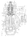
- reference numeral 2 designates an input shaft and 3 designates an output shaft, which are supported in a common cylindrical housing 1 and co-axially rotatable.
- a cylinder 30 is provided at abutting ends of the output shaft 3 and input shaft 2.
- the hollow input shaft 2 is inserted inside the cylinder 30 as shown, and supported at one axial end by a bearing bush fixedly fitted in the cylinder 30.
- the input shaft 2 and output shaft 3 are coaxially connected with each other through a torsion bar 4 inserted inside the hollow portion of input shaft 2 and pin-coupled and press-fit-fixed at both axial ends with both the shafts 2 and 3.
- An upper end (the right-hand end in the drawing) of input shaft 2 projecting outwardly from the housing 1 is connected to a steering wheel (not shown), the input shaft 2 and the output shaft 3 connected thereto through the torsion bar 4 rotating following rotation of the steering wheel.
- a bottomed cylinder housing 5 in which a nut member 6 forming at the inner periphery thereof ball screw thread is axially slidably housed.
- a lower half of the output shaft 3 projecting to the cylinder housing 5 is a screw thread shaft provided at the outer periphery thereof in a range of a predetermined length with ball screw thread corresponding to the ball screw thread at the inner periphery of nut member 6, and is screwed therewith through a large number of balls 7.
- a sector gear 8 rotatable around the axis perpendicular to the output shaft 3 and nut member 6, the sector gear 8 being engaged with a rack 60 formed at the outside of nut member 6 in a predetermined axial length.
- a rotary shaft of sector gear 8 is connected to a link mechanism for steering through a pitman arm (not shown) outside the cylinder housing 5.
- the rotation of output shaft 3 in response to the rotation of steering wheel is converted into axially sliding motion of nut member 6 through the ball screw thread, the sliding motion being converted into rotation of the sector gear 8 engageable with the rack 60, thereby performing steering corresponding to the rotation of steering wheel.
- the nut member 6 is provided with a cylindrical portion having at the outside the rack 60 and a disc 61 connected to the lower portion of the cylindrical portion, the disc 61 being fitted in the cylinder housing 5 through a sealing member 62 wound onto the outer periphery of the disc 61. Therefore, the hydraulic cylinder for generating the steering assisting power uses as a piston the nut member 6 slidable in the cylinder housing 5 and has two oil chambers S1 and S2 sealed at both sides of the disc 61 in a liquid-tight manner.
- the nut member 6 is biased by a pressure difference generated between the oil chambers S1 and S2 so that the sliding motion of nut member 6 caused by the pressure difference is converted into the steering motion through the rack 60 and sector gear 8, thereby carrying out steering assisting.
- Both the oil chambers S1 and S2 at the hydraulic cylinder are connected to a hydraulic pump P of the hydraulic pressure source and to an oil tank T through a hydraulic control valve 10 constituted at the joint of input shaft 2 and output shaft 3.
- the input shaft 2 and output shaft 3 are connected with each other through the torsion bar 4 so that, when the steering wheel is subjected to a steering torque, torsion corresponding there to is caused at the torsion bar 4 to create relative angular displacement between both the shafts 2 and 3.
- the hydraulic control valve 10 shown in the drawing controls feed of pressure oil to both the oil chambers S1 and S2 at the hydraulic cylinder by use of the relative angular displacement, and is, as well-known, provided with a spool 11 formed on the way of the input shaft 2 integrally therewith, and with a cylindrical valve body 12 fitted on the spool 11 and in the housing 1 and connected to the cylindrical portion 30 at the upper end of output shaft 3.
- movable throttles by oil grooves formed at the outer periphery of the spool 11 and at the inner periphery of the valve body 12 respectively, the movable throttles changing the degree of opening in the reverse direction corresponding to the relative angular displacement in such a manner that when one throttle is open (or closed), the other is closed (or open).
- One movable throttle is interposed between the hydraulic pump P and the oil chamber S1 and between the oil tank T and the oil chamber S2, the other being interposed between the hydraulic pump P and the oil chamber S2 and between the oil tank T and the oil chamber S1.
- a hydraulic reaction power unit 20 is juxtaposed under the hydraulic control valve 10.
- the hydraulic pressure reaction power unit 20 as disclosed in many well-known examples, such as the Japanese Patent Application Laid-Open No. Sho 61-200063 by the applicant for the present invention, is provided at the cylindrical portion 30 of the upper end of output shaft 3 with a plurality of bores perforating outside and inside the cylindrical portion 30, and plungers 21 are radially slidably movably inserted in the bores respectively.
- annular oil chamber 22 enclosed with the cylindrical portion 30 and housing 1 and communicating the respective bores with each other.
- the hydraulic reaction power unit 20 applies to the outer end face of each plunger 21 the hydraulic pressure introduced into the annular oil chamber 22 and corresponding to the vehicle speed so as to bring the inner end face of each plunger 21 into press-contact with the outer periphery of the input shaft 2 positioned inside the cylindrical portion 30.
- the relative angular displacement of the input shaft 2 with respect to the output shaft 3 in other words, the relative angular displacement between the spool 11 and the valve body 12 at the hydraulic control valve 10, is restrained by the strength corresponding to the hydraulic pressure, that is, the vehicle speed.
- a by-pass oil passage 25 connecting a discharge port of pump P and the oil tank T through a movable throttle 23 and a fixed throttle 24 in this order.
- the hydraulic pressure introduced into the annular oil chamber 22 is obtained between both the throttles 23 and 24 at the by-pass oil passage 25.
- the degree of opening of movable throttle 23 is adjusted according to an open-close signal from an electronic controller 26.
- the electronic controller 26 generates the open-close signal in order to increase the degree of opening of movable throttle 23 corresponding to an increase in the vehicle speed on the basis of the vehicle signal given from a vehicle speed sensor 27.
- the hydraulic pressure supplied through the hydraulic control valve 10 corresponding to the steering torque slides the nut member 6 which functions as a piston, the sliding motion is converted similarly through the rack 60 into the rotation of sector gear 8 engageable therewith, thereby obtaining the steering assisting power W s , and the resultant force (total resultant force W) of manual force W r and steering assisting power W s performs steering.
- the total resultant force W is given in the following equation obtained by substituting the equations (2) and (3) into that (1):
- the manual force W r for steering is obtained in such a manner that the steering torque T r applied to the steering wheel is converted by a conversion rate of ⁇ mZ/p due to the recirculating ball screw and engagement of the rack 60 with the sector gear 8.
- the steering assisting power W s is obtained so that the hydraulic strength AP m generated by the hydraulic cylinder is converted by a conversion rate of mZ/2 due to engagement of rack 60 with the sector gear 8.
- the present inventor has known that since the steering assisting power W s is represented by the second term in the equation (4), at the converting means for converting the action of hydraulic cylinder into the steering motion, concretely, between the rack 60 at the outer periphery of nut member 6 and the sector gear 8, when the magnitude of rotation of sector gear 8 in response to a specified magnitude of sliding motion of nut member 6 is larger at the central side of the rotation range of steering wheel than at the end side thereof in other words, at the central side of the rotation range of sector gear 8 than at the end side thereof, a conversion rate mZ/2 increases following an increase in the steering angle, resulting in that the steering assisting power W s increasing as the steering angle increases is obtainable without increasing the charged hydraulic pressure P m to the hydraulic cylinder and the cylinder's area A.
- the sector gear 8 a profile shifted gear whose pitch diameter is smaller at the central side of a rotation range than at the end side thereof as well-known in the Japanese Patent Application Publication No. Sho 46-35525 that the magnitude of rotation of the sector gear 8 in response to a specified magnitude of sliding motion of nut member 6 is changed.
- Fig. 2 the tooth profile of such the sector gear 8 is shown.
- the sector gear 8, as shown in Fig. 2 is cut of teeth at both sides of the rotation center line X-X so as to have a pitch diameter sequentially increasing in a manner of extending along the broken line in the drawing through a constant portion of a predetermined width at both sides of the line X-X to the lines Y-Y showing both ends of the rotation range.
- the sector gear 8 rotates at only an angle obtained by dividing the sliding length by the pitch radius.
- the sector gear 8 has the pitch diameter variable as the above-mentioned, the magnitude of rotation created at the sector gear 8 in response to a specified length of sliding motion of nut member 6 decreases as the rotation leads to both ends of rotation range.
- the pitch diameter of gear is a product of multiplying the module m by the number Z of teeth.
- the steering assisting power W s generated by the hydraulic cylinder provided with the nut member 6 as the piston is represented by the second term at the equation (4), in which the product (m ⁇ Z) of module m and tooth number Z is included.
- the magnitude of steering assisting power W s is smaller at the central side of the rotation range of sector gear 8 than at the end side thereof, in other words, at the central side of the rotation range of steering wheel than at the end side thereof.
- Fig. 3 shows the relation between the steering angle and the steering assisting power W s obtained thereby at the power steering apparatus of the present invention.
- the manual force W r shown in the first term at the equation (4) includes the product of module m and tooth number Z
- the manual force W r obtained in response to the constant steering torque T r applied to the steering wheel also increases following an increase in steering angle.
- the total resultant force W for steering increases following an increase in the rotation angle of steering wheel, whereby when large steering is repeated when the car is put into a garage or moved widthwise, it is possible to reduce a burden of labor required to operation of the steering wheel.
- the steering assisting power W s is small so that the hydraulic reaction power unit 20 as shown in Fig. 1 is also used to sufficiently ensure the running safety when the car is running straight at high speed.
- the present invention is applied to the steering mechanism of ball screw thread system, but the application range of the present invention of course is not limited to the above.
Landscapes
- Engineering & Computer Science (AREA)
- Chemical & Material Sciences (AREA)
- Combustion & Propulsion (AREA)
- Transportation (AREA)
- Mechanical Engineering (AREA)
- Steering Control In Accordance With Driving Conditions (AREA)
Applications Claiming Priority (2)
| Application Number | Priority Date | Filing Date | Title |
|---|---|---|---|
| JP1989109809U JPH0347879U (de) | 1989-09-19 | 1989-09-19 | |
| JP109809/89U | 1989-09-19 |
Publications (2)
| Publication Number | Publication Date |
|---|---|
| EP0418763A1 true EP0418763A1 (de) | 1991-03-27 |
| EP0418763B1 EP0418763B1 (de) | 1995-05-10 |
Family
ID=14519752
Family Applications (1)
| Application Number | Title | Priority Date | Filing Date |
|---|---|---|---|
| EP90117785A Expired - Lifetime EP0418763B1 (de) | 1989-09-19 | 1990-09-15 | Servolenkeinrichtung |
Country Status (4)
| Country | Link |
|---|---|
| EP (1) | EP0418763B1 (de) |
| JP (1) | JPH0347879U (de) |
| KR (1) | KR940002083B1 (de) |
| DE (1) | DE69019276T2 (de) |
Cited By (2)
| Publication number | Priority date | Publication date | Assignee | Title |
|---|---|---|---|---|
| EP0538836A1 (de) * | 1991-10-23 | 1993-04-28 | Mitsubishi Jidosha Kogyo Kabushiki Kaisha | Servolenkungsvorrichtung für Fahrzeug |
| CN116106336A (zh) * | 2023-04-13 | 2023-05-12 | 河北亿海管道集团有限公司 | 一种管件射线探伤设备 |
Citations (3)
| Publication number | Priority date | Publication date | Assignee | Title |
|---|---|---|---|---|
| DE2710849A1 (de) * | 1977-03-12 | 1978-09-14 | Daimler Benz Ag | Servolenkung fuer fahrzeuge mit rueckfuehrung |
| DE3532249A1 (de) * | 1984-09-10 | 1986-03-20 | Toyota Motor Co Ltd | Steuervorrichtung fuer eine servolenkung |
| WO1988001959A1 (fr) * | 1986-09-19 | 1988-03-24 | Zahnradfabrik Friedrichshafen Ag | Soupape de distribution rotative pour servo-directions hydrauliques |
-
1989
- 1989-09-19 JP JP1989109809U patent/JPH0347879U/ja active Pending
-
1990
- 1990-09-15 EP EP90117785A patent/EP0418763B1/de not_active Expired - Lifetime
- 1990-09-15 DE DE69019276T patent/DE69019276T2/de not_active Expired - Lifetime
- 1990-09-18 KR KR1019900014776A patent/KR940002083B1/ko not_active Expired - Lifetime
Patent Citations (3)
| Publication number | Priority date | Publication date | Assignee | Title |
|---|---|---|---|---|
| DE2710849A1 (de) * | 1977-03-12 | 1978-09-14 | Daimler Benz Ag | Servolenkung fuer fahrzeuge mit rueckfuehrung |
| DE3532249A1 (de) * | 1984-09-10 | 1986-03-20 | Toyota Motor Co Ltd | Steuervorrichtung fuer eine servolenkung |
| WO1988001959A1 (fr) * | 1986-09-19 | 1988-03-24 | Zahnradfabrik Friedrichshafen Ag | Soupape de distribution rotative pour servo-directions hydrauliques |
Cited By (2)
| Publication number | Priority date | Publication date | Assignee | Title |
|---|---|---|---|---|
| EP0538836A1 (de) * | 1991-10-23 | 1993-04-28 | Mitsubishi Jidosha Kogyo Kabushiki Kaisha | Servolenkungsvorrichtung für Fahrzeug |
| CN116106336A (zh) * | 2023-04-13 | 2023-05-12 | 河北亿海管道集团有限公司 | 一种管件射线探伤设备 |
Also Published As
| Publication number | Publication date |
|---|---|
| JPH0347879U (de) | 1991-05-07 |
| DE69019276D1 (de) | 1995-06-14 |
| KR910006097A (ko) | 1991-04-27 |
| KR940002083B1 (ko) | 1994-03-17 |
| DE69019276T2 (de) | 1995-09-07 |
| EP0418763B1 (de) | 1995-05-10 |
Similar Documents
| Publication | Publication Date | Title |
|---|---|---|
| US4739855A (en) | Vehicle steering system having a steering ratio changing mechanism | |
| JP4315683B2 (ja) | 自動車のアクスルステアリングモジュールの駆動装置並びに電気機械式自動車操舵装置 | |
| GB1424937A (en) | Automotive steering system process for the production of bis-halogen carbonyl anilines | |
| JPH0315591B2 (de) | ||
| GB2306928A (en) | Power steering for motor vehicles | |
| US7337872B2 (en) | Hydraulic power assisted steering system | |
| US7225894B2 (en) | Power steering apparatus | |
| US7322898B2 (en) | Active front steering actuator | |
| JP3130433B2 (ja) | 車両用操舵装置 | |
| US20210171090A1 (en) | Steering gear for a steer-by-wire steering system | |
| EP0418763A1 (de) | Servolenkeinrichtung | |
| EP0269088A2 (de) | Vierradlenkungssystem für Radfahrzeuge | |
| EP0475742A2 (de) | Hinterradlenkung für Fahrzeuge | |
| EP0310729B1 (de) | Lenkmechanismus mit veränderbarem Übersetzungsverhältnis | |
| US7389848B2 (en) | Hydraulic power steering assistant | |
| US20210362775A1 (en) | Motor control device and steering system | |
| US4217811A (en) | Lash compensator for power steering gear | |
| US3906837A (en) | Power steering gear with torsion rod valve centering mechanism | |
| JPH0581464B2 (de) | ||
| US5205372A (en) | Hydraulic power steering device | |
| JPH04310475A (ja) | 電動式動力舵取装置 | |
| US20030226711A1 (en) | Integrated differential steering actuator | |
| KR102876535B1 (ko) | 차량 스티어링 시스템 | |
| JP3032849B2 (ja) | 動力舵取装置 | |
| WO2003024764A1 (en) | Steering gear |
Legal Events
| Date | Code | Title | Description |
|---|---|---|---|
| PUAI | Public reference made under article 153(3) epc to a published international application that has entered the european phase |
Free format text: ORIGINAL CODE: 0009012 |
|
| AK | Designated contracting states |
Kind code of ref document: A1 Designated state(s): DE FR GB |
|
| 17P | Request for examination filed |
Effective date: 19910215 |
|
| 17Q | First examination report despatched |
Effective date: 19921012 |
|
| GRAA | (expected) grant |
Free format text: ORIGINAL CODE: 0009210 |
|
| AK | Designated contracting states |
Kind code of ref document: B1 Designated state(s): DE FR GB |
|
| REF | Corresponds to: |
Ref document number: 69019276 Country of ref document: DE Date of ref document: 19950614 |
|
| ET | Fr: translation filed | ||
| PLBE | No opposition filed within time limit |
Free format text: ORIGINAL CODE: 0009261 |
|
| STAA | Information on the status of an ep patent application or granted ep patent |
Free format text: STATUS: NO OPPOSITION FILED WITHIN TIME LIMIT |
|
| 26N | No opposition filed | ||
| REG | Reference to a national code |
Ref country code: GB Ref legal event code: IF02 |
|
| PGFP | Annual fee paid to national office [announced via postgrant information from national office to epo] |
Ref country code: GB Payment date: 20070912 Year of fee payment: 18 |
|
| GBPC | Gb: european patent ceased through non-payment of renewal fee |
Effective date: 20080915 |
|
| PG25 | Lapsed in a contracting state [announced via postgrant information from national office to epo] |
Ref country code: GB Free format text: LAPSE BECAUSE OF NON-PAYMENT OF DUE FEES Effective date: 20080915 |
|
| PGFP | Annual fee paid to national office [announced via postgrant information from national office to epo] |
Ref country code: DE Payment date: 20090910 Year of fee payment: 20 |
|
| PGFP | Annual fee paid to national office [announced via postgrant information from national office to epo] |
Ref country code: FR Payment date: 20091012 Year of fee payment: 20 |
|
| PG25 | Lapsed in a contracting state [announced via postgrant information from national office to epo] |
Ref country code: DE Free format text: LAPSE BECAUSE OF EXPIRATION OF PROTECTION Effective date: 20100915 |