EP0418886A2 - Vorrichtung und Verfahren zum Minimierung der Effekte, des in einem Elektrolyte gelösten Sauerstoffgehaltes, bei Analysatoren für niedrige Sauerstoffkonzentrationen - Google Patents
Vorrichtung und Verfahren zum Minimierung der Effekte, des in einem Elektrolyte gelösten Sauerstoffgehaltes, bei Analysatoren für niedrige Sauerstoffkonzentrationen Download PDFInfo
- Publication number
- EP0418886A2 EP0418886A2 EP90118118A EP90118118A EP0418886A2 EP 0418886 A2 EP0418886 A2 EP 0418886A2 EP 90118118 A EP90118118 A EP 90118118A EP 90118118 A EP90118118 A EP 90118118A EP 0418886 A2 EP0418886 A2 EP 0418886A2
- Authority
- EP
- European Patent Office
- Prior art keywords
- electrode
- electrolyte
- cell
- oxygen
- electrodes
- Prior art date
- Legal status (The legal status is an assumption and is not a legal conclusion. Google has not performed a legal analysis and makes no representation as to the accuracy of the status listed.)
- Granted
Links
Images
Classifications
-
- G—PHYSICS
- G01—MEASURING; TESTING
- G01N—INVESTIGATING OR ANALYSING MATERIALS BY DETERMINING THEIR CHEMICAL OR PHYSICAL PROPERTIES
- G01N27/00—Investigating or analysing materials by the use of electric, electrochemical, or magnetic means
- G01N27/26—Investigating or analysing materials by the use of electric, electrochemical, or magnetic means by investigating electrochemical variables; by using electrolysis or electrophoresis
- G01N27/403—Cells and electrode assemblies
- G01N27/404—Cells with anode, cathode and cell electrolyte on the same side of a permeable membrane which separates them from the sample fluid, e.g. Clark-type oxygen sensors
Definitions
- An electrochemical cell in its simplest terms, consists of an anode (the oxidizing electrode), a cathode (the reducing electrode) and an electrolyte.
- the electrolyte In order for the electrochemical or electrolytic cell to function, the electrolyte must be compatible with the mechanisms of oxidation and reduction at the electrodes. As well, it must provide a conductive path for the transport of ionic species between the electrodes.
- Electrolytic cells are used in electroplating, water purification, and the production of high purity gases and metals while galvanic cells (batteries and fuel cells) provide a convenient means of energy storage and generation.
- electrochemical cells are used for measurement in a variety of analytical procedures and many laboratory and process control instruments depend on the electrochemical cell as the sensing element for their function.
- the requirement to maintain a consistent electrolyte composition is commonly required in order to ensure the accuracy of measurement.
- the sample stream introduced into the electrolytic cell commonly contains components other than the one to be analyzed.
- these other components for example, carbon dioxide, contained as a component in a stream for oxygen analysis result in a neutralization reaction forming neutralization products. This reduces the transfer of ions through the electrolyte causing drift of measurement in analysis.
- the problems of the neutralization products being formed in the electrolyte were overcome by the invention disclosed in U.S. Patent 3,929,587. That invention allowed for oxygen level determinations in the presence of acid gases.
- Electrolytes inherently contain dissolved oxygen. This is not a problem when measuring in the ppm range. However, when measuring in the low ppb range, say between 1-10 ppb, the dissolved oxygen in the electrolyte contributes significantly to the measurement of oxygen from the gas sample.
- the present invention relates to a method and apparatus for the removal of dissolved oxygen from an electrolyte. This dissolved oxygen when removed allows for an accurate reading of oxygen concentration in the gas sample.
- the cell includes sensing electrodes for the component in the fluid stream to be analyzed.
- the sensing electrode (which functions as a cathode) is generally any semi-permeable electrode catalytically specific to oxygen.
- a non-specific cathode may be used as long as the reduction of oxygen at the cathode is proportional to the oxygen entering the electrolytic cell.
- a barrier cathode such as a platinum wire mesh, is interposed between the sensing cathode and the electrolyte in the cell cavity.
- An electrode an anode, such as a suspended platinum rod, is located in the electrolyte reservoir.
- An electrolytic path is established between the first and second electrodes through the common electrolyte.
- the cathode and anode are connected to a power source.
- a potential of less than 1.7 VDC (for 1M KOH), preferably 1.5 VDC, is applied between them. The voltage applied is slightly less than the voltage required to fully electrolyze water into the products of gaseous diatomic hydrogen and oxygen.
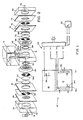
- a block functional diagram of the electrolytic system 10, of the preferred embodiment of the invention includes an electrolytic cell 12 having sensing electrodes 14a and 14b disposed therein.
- a reservoir 16 is in fluid flow communication with the cell 12 and includes an electrode 18b.
- An electrode 18a is disposed in cell 12.
- the load for the electrodes 14a and 14b is provided by a DC circuit and power conditioner 20.
- the electrolyte and the cell 12 with the electrodes 14a and 14b completes the electrolytic circuit.
- the power conditioner also provides the potential for electrodes 18a and 18b and the electrolyte common to the cell 12 and reservoir 16 by a separate DC circuit.
- the power conditioner will include the appropriate resistors, amplifiers, etc. in order to control specifically the potential applied to each set of electrodes.
- a meter 22 communicates with electrodes 14a and 14b via the power conditioner 20 to provide a direct reading corresponding to the electrolytic oxidation and reduction of the component to be analyzed.
- the gaseous stream containing the component to be analyzed flows from a source 24 through an inlet 28 and into an inlet plate 30.
- the inlet plate 30 also includes outlet 32.
- the inlet plate 30 includes a cavity-like recess 34 through which the gaseous stream flows.
- An apertured diffusion plate 38 meters the diffusion of the reducible gas in the sample stream flowing through the inlet plate 30.
- a current collector 40 is sandwiched between the diffusion plate 38 and an electrode retainer plate 42 having an aperture therein.
- the electrode 14a is received in the aperture.
- a permeable separator 44 is interposed between the electrode 14a and the platinum screen electrode 18a.
- An electrolyte plate 46 having flow passages therein abuts the electrode 18a on one side and on the other side receives an O ring 50.
- a housing 52 generally comprises the lower electrolytic cell 12 and the upper reservoir 16. Conduits 60a and 60b are formed in the cell 12 and are received in the bottom of the reservoir 16. A sleeve 64 in the reservoir is placed over the conduit 60a to isolate electrode 18a from 18b, and through which the wire for the electrode 18a passes. The electrode 18b is also secured in any suitable manner within the reservoir 16. The electrolyte in the cell 12 and the reservoir 16 are in fluid flow communication with one another only via the conduit 60b.
- an O-ring 66 On the other side of the housing 12 are an O-ring 66, an electrolyte plate 68, having flow passages therein, a stainless steel screen 70, a permeable separator 72, such as an asbestos separator, the electrode 14b, an electrode retainer plate 74, a current collector 76, a gas diffuser plate 78 and a downstream gas cavity end plate 80 including a gas vent 82.
- a permeable separator 72 such as an asbestos separator
- the electrode 14b On the other side of the housing 12 are an O-ring 66, an electrolyte plate 68, having flow passages therein, a stainless steel screen 70, a permeable separator 72, such as an asbestos separator, the electrode 14b, an electrode retainer plate 74, a current collector 76, a gas diffuser plate 78 and a downstream gas cavity end plate 80 including a gas vent 82.
- the end plate 82 does not communicate with a source of supply gas or the like but rather it simply includes the gas vent 82.
- the electrode 14b may be of a different structure and composition than the electrode 14a.
- the diffusion plate 78 may have apertures therein configured differently from that of 38 in that the diffusion rate of the gas through this diffusion plate is not as critical as the diffusion rate through the upstream diffuser plate.
- an electrolyte such as a solution of 1M potassium hydroxide - 1M potassium carbonate
- the conduit 60b provides fluid flow communication therebetween.
- the current collectors 40 and 76 specifically, the extending tabs on the current collectors, are connected to the power conditioner 20 through appropriate connectors (not shown). The polarities are as indicated in the drawings. This establishes a first electrolytic path between the sensing electrodes 14a and 14b.
- the electrodes 18a and 18b are connected to the power conditioner 20 through appropriate connectors (not shown). Again, the polarities are as indicated in the drawings. This establishes a second electrolytic path between the electrodes 18a and 18b and through the common electrolyte.
- resistance to current flow that results in this particular cell configuration is equivalent to approximately 10 ohms.
- a potential of approximately 1.5 volts is applied across the electrode 18a, which is a platinum screen that functions as a cathode (negative terminal) and the electrode 18b which is a platinum wire that functions as an anode (positive terminal).
- the potential at the electrodes is controlled by the power conditioner.
- the current produced by this electrolytic circuit is equivalent to the equilibrium rate of O2 availability at the cathode.
- a gaseous stream flows from the source 24 into the inlet 28 at a rate of about 2 scfh.
- a flow rate of between 1.0 to 3.0 scfh is preferred.
- the gas may be at a temperature of between 0 to 150° F and a pressure of less than 15.7 psia.
- the sensor 14a which functions as a cathode, may be any semi-permeable electrode catalytically specific to oxygen.
- a non-specific cathode may be used as long as the reduction of oxygen at the cathode is proportional to the oxygen entering the electrolytic cell.
- the cathode sensor 14a With three ppb oxygen partial pressure across the diffusion barrier 38, 1x10 ⁇ 6 cc per hour of oxygen flows to the cathode sensor 14a. The rate of oxygen exposed to the sensor 14a will result in a current flow of approximately 5 nano-amps in the cell.
- the power conditioner 20 communicating with the collecting screens 40 and 76 has an applied potential of 1.3 VDC.
- the sensor electrode 14b which functions as an anode, is illustrated as the same type of semi-permeable electrode catalytically specific to oxygen, such as a carbon-Teflon electrode. However, a solid metal electrode, such as platinum, gold, etc., may be used. In this embodiment, the oxygen is reduced at the electrode 14a.
- the applied potential provides the driving force for the transport of the anions or hydroxyl ions.
- the hydroxyl ions complete the first electrolytic path between the sensors 14a and 14b.
- Inherent in the electrolyte is dissolved oxygen. Measuring oxygen in the ppb range, the dissolved oxygen can contribute significantly and provide a reading error. That is, unless the dissolved oxygen contribution is eliminated, the dissolved oxygen in the electrolyte will also be reduced at the electrode 14a thereby providing an erroneous reading.
- the electrode 18a the barrier electrode, is interposed between the electrolyte and one side of the sensing electrode 14a.
- the gas to be measured contacts the electrode (wetted by the electrolyte) on the other side of the cathode 14a.
- the voltage applied between 18a and 18b is approximately 1.5 VDC. Water in the region adjacent to the electrode 18a is reduced resulting in a film of hydrogen ions on the surface. Any dissolved oxygen in the electrolyte which would ordinarily diffuse through and contact the electrode 14a reacts with the hydrogen at the barrier electrode 18a to form water.
- the oxygen produced at the anode 18b effervesces from the reservoir.
- the invention relates to any application to remove interferring components, such as O2 or H2, in an electrolyte which would interfere with the measurement of the desired component from the gas phase.
- the unwanted component in the electrolyte is prevented from contacting the sensing electrode. It maintains the electrolyte in the condition that enhances the function of a specific electrochemical reduction of O2 from the gas sample.
Landscapes
- Chemical & Material Sciences (AREA)
- Life Sciences & Earth Sciences (AREA)
- Health & Medical Sciences (AREA)
- Biochemistry (AREA)
- Chemical Kinetics & Catalysis (AREA)
- Electrochemistry (AREA)
- Physics & Mathematics (AREA)
- Analytical Chemistry (AREA)
- Molecular Biology (AREA)
- General Health & Medical Sciences (AREA)
- General Physics & Mathematics (AREA)
- Immunology (AREA)
- Pathology (AREA)
- Electrolytic Production Of Non-Metals, Compounds, Apparatuses Therefor (AREA)
- Sampling And Sample Adjustment (AREA)
- Measuring Oxygen Concentration In Cells (AREA)
Applications Claiming Priority (2)
| Application Number | Priority Date | Filing Date | Title |
|---|---|---|---|
| US410111 | 1989-09-20 | ||
| US07/410,111 US4960497A (en) | 1989-09-20 | 1989-09-20 | Apparatus and method for minimizing the effect of an electrolyte's dissolved oxygen content in low range oxygen analyzers |
Publications (3)
| Publication Number | Publication Date |
|---|---|
| EP0418886A2 true EP0418886A2 (de) | 1991-03-27 |
| EP0418886A3 EP0418886A3 (en) | 1993-01-13 |
| EP0418886B1 EP0418886B1 (de) | 1996-12-18 |
Family
ID=23623272
Family Applications (1)
| Application Number | Title | Priority Date | Filing Date |
|---|---|---|---|
| EP90118118A Expired - Lifetime EP0418886B1 (de) | 1989-09-20 | 1990-09-20 | Vorrichtung und Verfahren zur Minimierung der Effekte, des in einem Elektrolyten gelösten Sauerstoffgehaltes, bei Analysatoren für niedrige Sauerstoffkonzentrationen |
Country Status (5)
| Country | Link |
|---|---|
| US (1) | US4960497A (de) |
| EP (1) | EP0418886B1 (de) |
| JP (1) | JP3106247B2 (de) |
| CA (1) | CA2025715A1 (de) |
| DE (1) | DE69029446T2 (de) |
Families Citing this family (8)
| Publication number | Priority date | Publication date | Assignee | Title |
|---|---|---|---|---|
| US5256273A (en) * | 1992-04-07 | 1993-10-26 | Delta F Corporation | Micro fuel-cell oxygen gas sensor |
| US5284566A (en) * | 1993-01-04 | 1994-02-08 | Bacharach, Inc. | Electrochemical gas sensor with wraparound reference electrode |
| US5393392A (en) * | 1994-04-25 | 1995-02-28 | Delta F Corporation | Polarographic PPB oxygen gas sensor |
| US5690808A (en) * | 1996-01-25 | 1997-11-25 | Teledyne Industries, Inc. | Electrochemical gas sensors and methods for sensing electrochemical active gases in gas mixtures |
| US6176989B1 (en) | 1998-12-28 | 2001-01-23 | Teledyne Technologies Incorp. | Electrochemical gas sensor |
| US7664607B2 (en) | 2005-10-04 | 2010-02-16 | Teledyne Technologies Incorporated | Pre-calibrated gas sensor |
| JP4988037B2 (ja) * | 2008-03-04 | 2012-08-01 | エウレカ・ラボ株式会社 | 溶存水素と溶存酸素との反応の評価方法および溶存水素による水中の活性酸素消去能の評価方法 |
| US9322801B2 (en) * | 2009-05-14 | 2016-04-26 | Honeywell International Inc. | Apparatus and method of regenerating electrochemical gas sensors |
Family Cites Families (4)
| Publication number | Priority date | Publication date | Assignee | Title |
|---|---|---|---|---|
| US3929587A (en) * | 1974-09-23 | 1975-12-30 | Delta F Corp | Apparatus and method for maintaining a stable electrolyte in oxygen analysis |
| GB2140563B (en) * | 1983-04-27 | 1987-03-04 | Critikon Inc | Method and apparatus for zero calibration of oxygen-sensing polarographic devices |
| GB8419058D0 (en) * | 1984-07-26 | 1984-08-30 | Leitner M | Oxygen sensor |
| US4776942A (en) * | 1987-02-24 | 1988-10-11 | Beckman Industrial Corporation | Electrochemical sensor |
-
1989
- 1989-09-20 US US07/410,111 patent/US4960497A/en not_active Expired - Lifetime
-
1990
- 1990-09-19 CA CA002025715A patent/CA2025715A1/en not_active Abandoned
- 1990-09-20 DE DE69029446T patent/DE69029446T2/de not_active Expired - Fee Related
- 1990-09-20 JP JP02249024A patent/JP3106247B2/ja not_active Expired - Fee Related
- 1990-09-20 EP EP90118118A patent/EP0418886B1/de not_active Expired - Lifetime
Also Published As
| Publication number | Publication date |
|---|---|
| US4960497A (en) | 1990-10-02 |
| EP0418886B1 (de) | 1996-12-18 |
| JP3106247B2 (ja) | 2000-11-06 |
| DE69029446D1 (de) | 1997-01-30 |
| CA2025715A1 (en) | 1991-03-21 |
| JPH03191854A (ja) | 1991-08-21 |
| DE69029446T2 (de) | 1997-04-03 |
| EP0418886A3 (en) | 1993-01-13 |
Similar Documents
| Publication | Publication Date | Title |
|---|---|---|
| US4025412A (en) | Electrically biased two electrode, electrochemical gas sensor with a H.sub.2 | |
| JP2002503330A (ja) | 微小燃料電池酸素ガス・センサ | |
| Hersch | Trace monitoring in gases using galvanic systems | |
| EP0141282B1 (de) | Verfahren und Gerät zur Bestimmung von Differentialimpulsen in Echtzeit | |
| EP2534727B1 (de) | Elektrochemische detektionszelle für ein flüssigchromatografiesystem | |
| US5256273A (en) | Micro fuel-cell oxygen gas sensor | |
| EP2850422B1 (de) | Verfahren und vorrichtung zur messung des gesamtgehaltes an organischen elementen in wässrigen strömen | |
| Pihlar et al. | Amperometric determination of cyanide by use of a flow-through electrode | |
| US4960497A (en) | Apparatus and method for minimizing the effect of an electrolyte's dissolved oxygen content in low range oxygen analyzers | |
| US4985130A (en) | Amperometric method and apparatus | |
| US5076904A (en) | Electrochemical measuring cell for determining ammonia or hydrazine in a measuring sample | |
| US3929587A (en) | Apparatus and method for maintaining a stable electrolyte in oxygen analysis | |
| US5393392A (en) | Polarographic PPB oxygen gas sensor | |
| US6176989B1 (en) | Electrochemical gas sensor | |
| JP2007017317A (ja) | ガスセンサ、それを用いたガス濃度測定装置、及び窒素酸化物濃度の測定方法 | |
| JP2954174B1 (ja) | 定電位電解式ガスセンサ | |
| CA1114021A (en) | Potentiostated, three-electrode, solid polymer electrolyte (spe) gas sensor having highly invariant background current characteristics with temperature during zero-air operation | |
| JPH0418263B2 (de) | ||
| Guenat et al. | Coulometric Nanotitrators with Potentiometric Endpoint Detection | |
| Gas | Amperometric gas sensors | |
| JP2003028832A (ja) | ガス濃度検出器 | |
| CS228898B1 (cs) | Zařízení pre kontinuální ampsrometrickš měření koncentrace oxidantů v plynech |
Legal Events
| Date | Code | Title | Description |
|---|---|---|---|
| PUAI | Public reference made under article 153(3) epc to a published international application that has entered the european phase |
Free format text: ORIGINAL CODE: 0009012 |
|
| AK | Designated contracting states |
Kind code of ref document: A2 Designated state(s): AT BE CH DE DK ES FR GB GR IT LI LU NL SE |
|
| PUAL | Search report despatched |
Free format text: ORIGINAL CODE: 0009013 |
|
| AK | Designated contracting states |
Kind code of ref document: A3 Designated state(s): AT BE CH DE DK ES FR GB GR IT LI LU NL SE |
|
| 17P | Request for examination filed |
Effective date: 19930702 |
|
| 17Q | First examination report despatched |
Effective date: 19941228 |
|
| GRAH | Despatch of communication of intention to grant a patent |
Free format text: ORIGINAL CODE: EPIDOS IGRA |
|
| GRAH | Despatch of communication of intention to grant a patent |
Free format text: ORIGINAL CODE: EPIDOS IGRA |
|
| GRAH | Despatch of communication of intention to grant a patent |
Free format text: ORIGINAL CODE: EPIDOS IGRA |
|
| RBV | Designated contracting states (corrected) |
Designated state(s): DE GB IT |
|
| ITF | It: translation for a ep patent filed | ||
| GRAA | (expected) grant |
Free format text: ORIGINAL CODE: 0009210 |
|
| AK | Designated contracting states |
Kind code of ref document: B1 Designated state(s): DE GB IT |
|
| REF | Corresponds to: |
Ref document number: 69029446 Country of ref document: DE Date of ref document: 19970130 |
|
| PLBE | No opposition filed within time limit |
Free format text: ORIGINAL CODE: 0009261 |
|
| STAA | Information on the status of an ep patent application or granted ep patent |
Free format text: STATUS: NO OPPOSITION FILED WITHIN TIME LIMIT |
|
| 26N | No opposition filed | ||
| REG | Reference to a national code |
Ref country code: GB Ref legal event code: IF02 |
|
| PG25 | Lapsed in a contracting state [announced via postgrant information from national office to epo] |
Ref country code: IT Free format text: LAPSE BECAUSE OF NON-PAYMENT OF DUE FEES;WARNING: LAPSES OF ITALIAN PATENTS WITH EFFECTIVE DATE BEFORE 2007 MAY HAVE OCCURRED AT ANY TIME BEFORE 2007. THE CORRECT EFFECTIVE DATE MAY BE DIFFERENT FROM THE ONE RECORDED. Effective date: 20050920 |
|
| PGFP | Annual fee paid to national office [announced via postgrant information from national office to epo] |
Ref country code: DE Payment date: 20070930 Year of fee payment: 18 |
|
| PGFP | Annual fee paid to national office [announced via postgrant information from national office to epo] |
Ref country code: GB Payment date: 20070823 Year of fee payment: 18 |
|
| GBPC | Gb: european patent ceased through non-payment of renewal fee |
Effective date: 20080920 |
|
| PG25 | Lapsed in a contracting state [announced via postgrant information from national office to epo] |
Ref country code: DE Free format text: LAPSE BECAUSE OF NON-PAYMENT OF DUE FEES Effective date: 20090401 |
|
| PG25 | Lapsed in a contracting state [announced via postgrant information from national office to epo] |
Ref country code: GB Free format text: LAPSE BECAUSE OF NON-PAYMENT OF DUE FEES Effective date: 20080920 |