EP0418922A2 - Mesomorphe Verbindung, dieselbe enthaltende flüssigkristalline Zusammensetzung und dieselbe benutzende flüssigkristalline Vorrichtung - Google Patents
Mesomorphe Verbindung, dieselbe enthaltende flüssigkristalline Zusammensetzung und dieselbe benutzende flüssigkristalline Vorrichtung Download PDFInfo
- Publication number
- EP0418922A2 EP0418922A2 EP90118200A EP90118200A EP0418922A2 EP 0418922 A2 EP0418922 A2 EP 0418922A2 EP 90118200 A EP90118200 A EP 90118200A EP 90118200 A EP90118200 A EP 90118200A EP 0418922 A2 EP0418922 A2 EP 0418922A2
- Authority
- EP
- European Patent Office
- Prior art keywords
- liquid crystal
- crystal composition
- crystal device
- mesomorphic compound
- same manner
- Prior art date
- Legal status (The legal status is an assumption and is not a legal conclusion. Google has not performed a legal analysis and makes no representation as to the accuracy of the status listed.)
- Granted
Links
- 0 CC(S)=*N=C(C)c1cc(C)c(C)cc1 Chemical compound CC(S)=*N=C(C)c1cc(C)c(C)cc1 0.000 description 36
- JAPMJSVZDUYFKL-UHFFFAOYSA-N C1C2C1CCC2 Chemical compound C1C2C1CCC2 JAPMJSVZDUYFKL-UHFFFAOYSA-N 0.000 description 3
- URLKBWYHVLBVBO-UHFFFAOYSA-N Cc1ccc(C)cc1 Chemical compound Cc1ccc(C)cc1 URLKBWYHVLBVBO-UHFFFAOYSA-N 0.000 description 2
- LXVWHMFJDHFVHJ-MDWZMJQESA-N C/C(/c1cc(F)c(C)cc1)=N\N=C/S Chemical compound C/C(/c1cc(F)c(C)cc1)=N\N=C/S LXVWHMFJDHFVHJ-MDWZMJQESA-N 0.000 description 1
- AMPLGBBDJQSCOM-UHFFFAOYSA-N CC(c(cc1)cc(F)c1O)=N Chemical compound CC(c(cc1)cc(F)c1O)=N AMPLGBBDJQSCOM-UHFFFAOYSA-N 0.000 description 1
- AHYADXURBXWBFA-UHFFFAOYSA-N CC(c(cc1)cc(F)c1O)C#[N]C Chemical compound CC(c(cc1)cc(F)c1O)C#[N]C AHYADXURBXWBFA-UHFFFAOYSA-N 0.000 description 1
- ZVGYOSJGSRYKPT-UHFFFAOYSA-N CC(c1ccc(C)cc1)=N Chemical compound CC(c1ccc(C)cc1)=N ZVGYOSJGSRYKPT-UHFFFAOYSA-N 0.000 description 1
- ATQUFXWBVZUTKO-UHFFFAOYSA-N CC1=CCCC1 Chemical compound CC1=CCCC1 ATQUFXWBVZUTKO-UHFFFAOYSA-N 0.000 description 1
- QRMPKOFEUHIBNM-UHFFFAOYSA-N CC1CCC(C)CC1 Chemical compound CC1CCC(C)CC1 QRMPKOFEUHIBNM-UHFFFAOYSA-N 0.000 description 1
- CZCXPEWHAVZECD-UHFFFAOYSA-N CC1CCC(CS)CC1 Chemical compound CC1CCC(CS)CC1 CZCXPEWHAVZECD-UHFFFAOYSA-N 0.000 description 1
- DDZACMDGXVXOOH-UHFFFAOYSA-N Cc(cc1)ccc1-c(cc1)ccc1O Chemical compound Cc(cc1)ccc1-c(cc1)ccc1O DDZACMDGXVXOOH-UHFFFAOYSA-N 0.000 description 1
- WUICFSLEKOURIK-DCXVBLDQSA-N Cc(cc1)ccc1C(SC/C(/c(cc1)cc(C)c1O)=N\C)=N Chemical compound Cc(cc1)ccc1C(SC/C(/c(cc1)cc(C)c1O)=N\C)=N WUICFSLEKOURIK-DCXVBLDQSA-N 0.000 description 1
- IWDCLRJOBJJRNH-UHFFFAOYSA-N Cc(cc1)ccc1O Chemical compound Cc(cc1)ccc1O IWDCLRJOBJJRNH-UHFFFAOYSA-N 0.000 description 1
- ZELNMWPKGYYFIQ-UHFFFAOYSA-N Cc1c(C)cc(CS)cc1 Chemical compound Cc1c(C)cc(CS)cc1 ZELNMWPKGYYFIQ-UHFFFAOYSA-N 0.000 description 1
- FHMUFDYPMAJAFT-UHFFFAOYSA-N Cc1ccc(C(CSC(c(cc2)cc(F)c2O)=N)N)cc1 Chemical compound Cc1ccc(C(CSC(c(cc2)cc(F)c2O)=N)N)cc1 FHMUFDYPMAJAFT-UHFFFAOYSA-N 0.000 description 1
- SHWKZEFERHFBTQ-UHFFFAOYSA-N Cc1ccc(cc(cc2)O)c2c1 Chemical compound Cc1ccc(cc(cc2)O)c2c1 SHWKZEFERHFBTQ-UHFFFAOYSA-N 0.000 description 1
- YXFVVABEGXRONW-UHFFFAOYSA-N Cc1ccccc1 Chemical compound Cc1ccccc1 YXFVVABEGXRONW-UHFFFAOYSA-N 0.000 description 1
- BXAVKNRWVKUTLY-UHFFFAOYSA-N Oc(cc1)ccc1S Chemical compound Oc(cc1)ccc1S BXAVKNRWVKUTLY-UHFFFAOYSA-N 0.000 description 1
Images

Classifications
-
- C—CHEMISTRY; METALLURGY
- C07—ORGANIC CHEMISTRY
- C07D—HETEROCYCLIC COMPOUNDS
- C07D285/00—Heterocyclic compounds containing rings having nitrogen and sulfur atoms as the only ring hetero atoms, not provided for by groups C07D275/00 - C07D283/00
- C07D285/01—Five-membered rings
- C07D285/02—Thiadiazoles; Hydrogenated thiadiazoles
- C07D285/04—Thiadiazoles; Hydrogenated thiadiazoles not condensed with other rings
- C07D285/12—1,3,4-Thiadiazoles; Hydrogenated 1,3,4-thiadiazoles
-
- C—CHEMISTRY; METALLURGY
- C09—DYES; PAINTS; POLISHES; NATURAL RESINS; ADHESIVES; COMPOSITIONS NOT OTHERWISE PROVIDED FOR; APPLICATIONS OF MATERIALS NOT OTHERWISE PROVIDED FOR
- C09K—MATERIALS FOR MISCELLANEOUS APPLICATIONS, NOT PROVIDED FOR ELSEWHERE
- C09K19/00—Liquid crystal materials
- C09K19/04—Liquid crystal materials characterised by the chemical structure of the liquid crystal components, e.g. by a specific unit
- C09K19/06—Non-steroidal liquid crystal compounds
- C09K19/34—Non-steroidal liquid crystal compounds containing at least one heterocyclic ring
-
- C—CHEMISTRY; METALLURGY
- C09—DYES; PAINTS; POLISHES; NATURAL RESINS; ADHESIVES; COMPOSITIONS NOT OTHERWISE PROVIDED FOR; APPLICATIONS OF MATERIALS NOT OTHERWISE PROVIDED FOR
- C09K—MATERIALS FOR MISCELLANEOUS APPLICATIONS, NOT PROVIDED FOR ELSEWHERE
- C09K19/00—Liquid crystal materials
- C09K19/04—Liquid crystal materials characterised by the chemical structure of the liquid crystal components, e.g. by a specific unit
- C09K19/06—Non-steroidal liquid crystal compounds
- C09K19/34—Non-steroidal liquid crystal compounds containing at least one heterocyclic ring
- C09K19/3491—Non-steroidal liquid crystal compounds containing at least one heterocyclic ring having sulfur as hetero atom
- C09K19/3497—Non-steroidal liquid crystal compounds containing at least one heterocyclic ring having sulfur as hetero atom the heterocyclic ring containing sulfur and nitrogen atoms
-
- C—CHEMISTRY; METALLURGY
- C09—DYES; PAINTS; POLISHES; NATURAL RESINS; ADHESIVES; COMPOSITIONS NOT OTHERWISE PROVIDED FOR; APPLICATIONS OF MATERIALS NOT OTHERWISE PROVIDED FOR
- C09K—MATERIALS FOR MISCELLANEOUS APPLICATIONS, NOT PROVIDED FOR ELSEWHERE
- C09K19/00—Liquid crystal materials
- C09K19/04—Liquid crystal materials characterised by the chemical structure of the liquid crystal components, e.g. by a specific unit
- C09K19/42—Mixtures of liquid crystal compounds covered by two or more of the preceding groups C09K19/06 - C09K19/40
-
- C—CHEMISTRY; METALLURGY
- C09—DYES; PAINTS; POLISHES; NATURAL RESINS; ADHESIVES; COMPOSITIONS NOT OTHERWISE PROVIDED FOR; APPLICATIONS OF MATERIALS NOT OTHERWISE PROVIDED FOR
- C09K—MATERIALS FOR MISCELLANEOUS APPLICATIONS, NOT PROVIDED FOR ELSEWHERE
- C09K19/00—Liquid crystal materials
- C09K19/04—Liquid crystal materials characterised by the chemical structure of the liquid crystal components, e.g. by a specific unit
- C09K19/42—Mixtures of liquid crystal compounds covered by two or more of the preceding groups C09K19/06 - C09K19/40
- C09K19/46—Mixtures of liquid crystal compounds covered by two or more of the preceding groups C09K19/06 - C09K19/40 containing esters
Definitions
- the present invention relates to a novel mesomorphic compound, a liquid crystal composition containing the compound and liquid crystal device using the composition, and more particularly to a novel liquid crystal composition with improved responsiveness to an electric field and a liquid crystal device using the liquid crystal composition for use in a liquid crystal display apparatus, a liquid crystal-optical shutter, etc.
- liquid crystal devices have been used as an electro-optical device in various fields.
- Most liquid crystal devices which have been put into practice use TN (twisted nematic) type liquid crystals, as shown in "Voltage-Dependent Optical Activity of a Twisted Nematic Liquid Crystal” by M. Schadt and W. Helfrich “Applied Physics Letters” Vol. 18, No. 4 (Feb. 15, 1971) pp. 127-128.
- an electrode arrangement wherein scanning electrodes and signal electrodes are arranged in a matrix, and for driving, a multiplex driving scheme is adopted wherein an address signal is sequentially, periodically and selectively applied to the scanning electrodes and prescribed data signals are selectively applied in parallel to the signal electrodes in synchronism with the address signal.
- a certain electric field is applied to regions where a scanning electrode is selected and signal electrodes are not selected or regions where a scanning electrode is not selected and a signal electrode is selected (which regions are so called "half-selected points"). If the difference between a voltage applied to the selected points and a voltage applied to the half-selected points is sufficiently large, and a voltage threshold level required for allowing liquid crystal molecules to be aligned or oriented perpendicular to an electric field is set to a value therebetween, display devices normally operate.
- liquid crystal molecules are horizontally oriented with respect to the electrode surface as stable state and are vertically oriented with respect to the electrode surface only when an electric field is effectively applied) is driven (i.e. repeatedly scanned) by making use of a time storage effect.
- the voltage averaging method, the two-frequency driving method, the multiple matrix method, etc. has been already proposed.
- any method is not sufficient to overcome the above-mentioned drawbacks. As a result, it is the present state that the development of large image area or high packaging density with respect to display elements is delayed because it is difficult to sufficiently increase the number of scanning lines.
- liquid crystal devices having bistability have been proposed by Clark and Lagerwall (e.g. Japanese Laid-Open Patent Appln. No. 56-107216, U.S.P. No. 4367924, etc.).
- ferroelectric liquid crystals having chiral smectic C-phase (SmC * ) or H-phase (SmH * ) are generally used as the liquid crystals having bistability. These liquid crystals have bistable states of first and second optically stable states with respect to an electric field applied thereto.
- the bistable liquid crystal molecules are oriented to first and second optically stable states with respect to one and the other electric field vectors, respectively. Further, this type of liquid crystal has a property (bistability) of assuming either one of the two stable states in response to an applied electric field and retaining the resultant state in the absence of an electric field.
- such a ferroelectric liquid crystal has an excellent property, i.e., a high-speed responsiveness. This is because the spontaneous polarization of the ferroelectric liquid crystal and an applied electric field directly interact with each other to induce transition of orientation states. The resultant response speed is faster than the response speed due to the interaction between dielectric anisotropy and an electric field by 3 to 4 digits.
- a ferroelectric liquid crystal potentially has very excellent characteristics, and by making use of these properties, it is possible to provide essential improvements to many of the above-mentioned problems with the conventional TN-type devices.
- the application to a high-speed optical shutter and a display of a high density and a large picture is expected.
- ferroelectric liquid crystal materials developed heretofore cannot be said to satisfy sufficient characteristics required for a liquid crystal device including low-temperature operation characteristic, high-speed responsiveness, etc.
- T ⁇ /(Ps'E)
- a high response speed can be obtained by (a) increasing the spontaneous polarization Ps, (b) lowering the viscosity n, or (c) increasing the applied voltage E.
- the driving voltage has a certain upper limit in view of driving with IC, etc., and should desirably be as low as possible. Accordingly, it is actually necessary to lower the viscosity or increase the spontaneous polarization.
- a ferroelectric chiral smectic liquid crystal having a large spontaneous polarization generally provides a large internal electric field in a cell given by the spontaneous polarization and is liable to pose many constraints on the device construction giving bistability. Further, an excessively large spontaneous polarization is liable to accompany an increase in viscosity, so that remarkable increase in response speed may not be attained as a result.
- the response speed changes by a factor of about 20, so that it actually exceeds the range controllable by driving voltage and frequency.
- ferroelectric liquid crystal device requires a ferroelectric chiral smectic liquid crystal composition having a low viscosity, a high-speed responsiveness and a small temperature-dependence of response speed.
- An object of the present invention is to provide a novel mesomorphic compound, a liquid crystal composition with improved responsiveness containing the mesomorphic compound for providing a practical ferroelectric liquid crystal device, and a liquid crystal device using the liquid crystal composition.
- Another object of the present invention is to provide a liquid crystal device using a liquid crystal composition containing a novel mesomorphic compound and showing improved display characteristics due to AC stabilization effect.
- liquid crystal composition containing at least one species of the mesomorohic compound as described above.
- the present invention further provides a liquid crystal device comprising a pair of substrates and such a liquid crystal composition as described above disposed between the electrode plates.
- thiadiazole derivatives or electro-optical display devices using compositions comprising the thiadiazole derivatives have been disclosed in WO 88/08019 and Japanese Laid-Open Patent Applications (KOKAI) Nos. 222148/1988 and 61472/1989.
- WO 88/08019 and Japanese Laid-Open Patent Applications described above respectively disclose a broad general formula which can encompass a fluorophenylthiadiazole derivative wherein a fluorine atom is laterally disposed.
- WO 88/08019 only one compound represented by the following formula: is disclosed as a specific embodiment corresponding to the above compound having a laterally substituted fluorine atom.
- 4-substituted-3- fluorophenylthiadiazole derivative having three rings wherein a 3-fluorophenyl group having a laterally substituted fluorine atom is disposed at a terminal of the ring structure and a thiadiazole ring is disposed in the center of the ring structure, or having two rings can have a lowered clear point (transition temperature to an isotropic liquid) because a fluorine atom is laterally disposed.
- the above compound having three rings can be used as a mesomorphic compound having a wide temperature range of a mesomorphic phase (particularly a smectic C (SmC) phase) because a thiadiazole ring is disposed in the center of the ring structure.
- a liquid crystal device using a ferroelectric chiral smectic liquid crystal composition containing at least one species of the above-mentioned compound of the invention shows improved characteristics such as a good alignment characteristic, high-speed responsiveness and a decreased temperature-dependence of response speed to provide good display characteristics.
- R, and R 2 may include the following combinations (i) to (vi): and wherein m and I respectively denote an integer of 1 -17; p, r and s respectively denote an integer of 0 - 7; q is 0 or 1; R 3 , R 4 and R 5 respectively denote a linear or branched alkyl group; and X 1 and X 2 respectively denote a single bond, with proviso that X, denotes a single bond when n is 0.
- the compounds represented by the general formula (I) may be synthesized through the following reaction schemes.
- R, , R 2 , and n are the same as defined above.
- mesomorphic compounds represented by the above-mentioned general formula (I) may include those shown by the following structural formulas.
- the liquid crystal composition according to the present invention may be obtained by mixing at least one species of the compound represented by the formula (I) and at least one species of another ferroelectric or non-ferroelectric mesomorphic compound so that the resultant composition contains 1 - 85 wt. %, preferably 1 - 40 wt. % of the compound(s) represented by the formula (I).
- the liquid crystal composition according to the present invention may preferably be formulated as a ferroelectric liquid crystal composition, particularly a ferroelectric chiral smectic liquid crystal composition.
- the ferroelectric liquid crystal device according to the present invention may preferably be prepared by heating the liquid crystal composition prepared as described above into an isotropic liquid under vacuum, filling a blank cell comprising a pair of oppositely spaced electrode plates with the composition, gradually cooling the cell to form a liquid crystal layer and restoring the normal pressure.
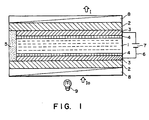
- Figure 1 is a schematic sectional view of an embodiment of the ferroelectric liquid crystal device prepared as described above for explanation of the structure thereof.
- the ferroelectric liquid crystal device includes a ferroelectric liquid crystal layer 1 disposed between a pair of glass substrates 2 each having thereon a transparent electrode 3 and an insulating alignment control layer 4.
- Lead wires 6 are connected to the electrodes so as to apply a driving voltage to the liquid crystal layer 1 from a power supply 7.
- a pair of polarizers 8 are disposed so as to modulate incident light lo from a light source 9 in cooperation with the liquid crystal 1 to provide modulated light I.
- Each of two glass substrates 2 is coated with a transparent electrode 3 comprising a film of ln 2 0 3 , Sn0 2 or ITO (indium-tin-oxide) to form an electrode plate.
- a transparent electrode 3 comprising a film of ln 2 0 3 , Sn0 2 or ITO (indium-tin-oxide) to form an electrode plate.
- an insulating alignment control layer 4 is formed by rubbing a film of a polymer such as polyimide with gauze or acetate fiber-planted cloth so as to align the liquid crystal molecules in the rubbing direction.
- the alignment control layer of two layers, e.g., by first forming an insulating layer of an inorganic material, such as silicon nitride, silicon nitride containing hydrogen, silicon carbide, silicon carbide containing hydrogen, silicon oxide, boron nitride, boron nitride containing hydrogen, cerium oxide, aluminum oxide, zirconium oxide, titanium oxide, or magnesium fluoride, and forming thereon an alignment control layer of an organic insulating material, such as polyvinyl alcohol, polyimide, polyamide-imide, polyester-imide, polyparaxylylene, polyester, polycarbonate, polyvinyl acetal, polyvinyl chloride, polyvinyl acetate, polyamide, polystyrene, cellulose resin, melamine resin, urea resin, acrylic resin, or photoresist resin.
- an inorganic material such as silicon nitride, silicon nitride containing hydrogen, silicon carbide, silicon carbide containing hydrogen, silicon
- inorganic insulating alignment control layer may be formed by vapor deposition, while an organic insulating alignment control layer may be formed by applying a solution of an organic insulating material or a precursor thereof in a concentration of 0.1 to 20 wt. %, preferably 0.2 - 10 wt. %, by spinner coating, dip coating, screen printing, spray coating or roller coating, followed by curing or hardening under prescribed hardening condition (e.g., by heating).
- the insulating alignment control layer may have a thickness of ordinarily 30 A - 1 micron, preferably 30 - 3000 A, further preferably 50 - 1000 A.
- the two glass substrates 2 with transparent electrodes 3 (which may be inclusively referred to herein as "electrode plates") and further with insulating alignment control layers 4 thereof are held to have a prescribed (but arbitrary) gap with a spacer 5.
- a cell structure with a prescribed gap may be formed by sandwiching spacers of silica beads or alumina beads having a prescribed diameter with two glass plates, and then sealing the periphery thereof with, e.g., an epoxy adhesive.
- a polymer film or glass fiber may also be used as a spacer.
- a ferroelectric liquid crystal is sealed up to provide a ferroelectric liquid crystal layer 1 in a thickness of generally 0.5 to 20 microns, preferably 1 to 5 microns.
- the transparent electrodes 3 are connected to the external power supply 7 through the lead wires 6. Further, outside the glass substrates 2, polarizers 8 are applied.
- the device shown in Figure 1 is of a transmission type and is provided with a light source 9.
- FIG. 2 is a schematic illustration of a ferroelectric liquid crystal cell (device) for explaining operation thereof.
- Reference numerals 21 a and 21 b denote substrates (glass,plates) on which a transparent electrode of, e.g., ln 2 0 3 , Sn0 2 , ITO (indium-tin-oxide), etc., is disposed, respectively.
- a liquid crystal of an SmC *- phase (chiral smectic C phase) or SmH *- phase (chiral smectic H phase) in which liquid crystal molecular layers 22 are aligned perpendicular to surfaces of the glass plates is hermetically disposed therebetween.
- Full lines 23 show liquid crystal molecules.
- Each liquid crystal molecule 23 has a dipole moment (Pi) 24 in a direction perpendicular to the axis thereof.
- the liquid crystal molecules 23 continuously form a helical structure in the direction of extension of the substrates.
- a voltage higher than a certain threshold level is applied between electrodes formed on the substrates 21 a and 21 b, a helical structure of the liquid crystal molecule 23 is unwound or released to change the alignment direction of respective liquid crystal molecules 23 so that the dipole moments (P l ) 24 are all directed in the direction of the electric field.
- the liquid crystal molecules 23 have an elongated shape and show refractive anisotropy between the long axis and the short axis thereof.
- the liquid crystal cell when, for instance, polarizers arranged in a cross nicol relationship, i.e., with their polarizing directions crossing each other, are disposed on the upper and the lower surfaces of the glass plates, the liquid crystal cell thus arranged functions as a liquid crystal optical modulation device of which optical characteristics vary depending upon the polarity of an applied voltage.
- the helical structure of the liquid crystal molecules is unwound to provide a non-helical structure even in the absence of an electric field, whereby the dipole moment assumes either of the two states, i.e., Pa in an upper direction 34a or Pb in a lower direction 34b as shown in Figure 3, thus providing a bistable condition.
- the device may be driven by a driving method as disclosed in Japanese Laid-Open Patent Applications (KOKAI) Nos. 193426/1984, 193427/1984, 156046/1985, 156047/1985. etc.
- KKAI Japanese Laid-Open Patent Applications
- Example Compound No. 1-84 2-(3-fluoro-4-octyloxyphenyl)-5-(4-decylphenyl)-1,3,4-thiadiazole (Example Compound No. 1-84) was synthesized through the following steps i) to iii).
- Example Compound No. I-103 2-(3-fluoro-4-acetoxyphenyl)-5-(4-hexylphenyl)-1,3,4-thiadiazole was synthesized in the same manner as in Example 1.
- Example Compound No. 1-72 2-(3-fluoro-4-hexyloxyphenyl)-5-(4-hexylphenyl)-1,3,4-thiadiazole (Example Compound No. 1-72) was synthesized through the following steps i) and ii).
- the resultant crystal was dissolved in toluene and washed with water, followed by drying with anhydrous magnesium sulfate.
- the magnesium sulfate was recovered by filtration and the filtrate was condensed into a solid.
- the solid was purified by silica gel column chromatography (eluent: toluene) and recrystallized from a mixture solvent (ethanol/hexane) to obtain 0.13 g of 2-(3-fluoro-4-hexyloxyphenyl)-5-(4-hexylphenyl)-1,3,4-thiadiazole (Yield: 35.1 %).
- Example Compound No. 1-70 2-(3-fluoro-4-butyloxyphenyl)-5-(4- hexylphenyl)-1,3,4-thiadiazole
- Example Compound No. 1 2-hexyl-5-(3-fluoro-4-heptanoyloxyphenyl)-1,3,4-thiadiazole (Example Compound No. 1-9) was synthesized through the following steps i) to iv).
- the resultant organic layer was washed with a 5 %-aqueous solution of sodium hydrogencarbonate in a solution of salt and further washed with a solution of salt, followed by drying with anhydrous sodium sulfate.
- the sodium sulfate was recovered by filtration and the filtrate was condensed into a solid. Hexane was added to the solid and subjected to filtration to obtain 9.98 g of methyl 3-fluoro-4-hydroxybenzoate (Yield: 91.6 %).
- the resultant water layer was subjected to extraction with ethyl acetate to be added to the resultant organic layer, followed by drying with anhydrous sodium sulfate.
- the sodium sulfate was recovered by filtration and the filtrate was condensed into a solid.
- Hexane was added to the solid, followed by cooling with iced water to precipitate a crystal.
- the crystal was recovered by filtration to obtain 5.96 g of N-heptanoyi-N'-(3-fiuoro-4-heptanoyloxybenzo)hydrazide (Yield: 51.4 %).
- a liquid crystal composition A was prepared by mixing the following compounds in respectively indicated proportions.
- the liquid crystal composition A was further mixed with the following Example Compound No. 1-84 in the proportions indicated below to provide a liquid crystal composition B.
- the liquid crystal composition B showed the following phase transition series.
- each glass plate provided with an ITO film and treated in the above described manner was coated with a 1.5 %-solution of polyimide resin precursor (SP-510, available from Toray K.K.) in dimethylacetoamide by a spinner coater rotating at 2000 rpm for 15 seconds. Thereafter, the coating film was subjected to heat curing at 300 °C for 60 min. to obtain about 250 A-thick film. The coating film was rubbed with acetate fiber-planted cloth. The thus treated two glass plates were washed with isopropyl alcohol.
- SP-510 polyimide resin precursor
- alumina beads with an average particle size of 2.0 microns were dispersed on one of the glass plates, the two glass plates were applied to each other with a bonding sealing agent (Lixon Bond, available from Chisso K.K.) so that their rubbed directions were parallel to each other and heated at 100 °C for 60 min. to form a blank cell.
- the cell gap was found to be about 2 microns as measured by a Berek compensator.
- liquid crystal composition B was heated into an isotropic liquid, and injected into the above prepared cell under vacuum and, after sealing, was gradually cooled at a rate of 20 °C/hour to 25 °C to prepare a ferroelectric liquid crystal device.
- the ferroelectric liquid crystal device was subjected to measurement of the magnitude of spontaneous polarization Ps and optical response time (time from voltage application until the transmittance change reaches 90 % of the maximum under the application of a peak-to-peak voltage Vpp of 20 V in combination with right-angle cross-nicol polarizers).
- a liquid crystal composition C was prepared by mixing the following compounds in respectively indicated proportions.
- liquid crystal composition C was further mixed with the following Example Compounds in the proportions indicated below to provide a liquid crystal composition D.
- a ferroelectric liquid crystal device was prepared in the same manner as in Example 6 except for using the composition D.
- the ferroelectric liquid crystal device In the ferroelectric liquid crystal device, a monodomain with a good and uniform alignment characteristic was observed.
- the ferroelectric liquid crystal device was subjected to measurement of response time and observation of a switching state, etc. in the same manner as in Example 6, whereby the following results were obtained.
- a ferroelectric liquid crystal device was prepared in the same manner as in Example 6 except that the above liquid crystal composition C prepared in Example 7 was injected into a cell, and the device was subjected to measurement of optical response time. The results are shown below.
- a liquid crystal composition E was prepared in the same manner as in Example 7 except that the following Example Compounds were used instead of Example Compounds Nos. 1-4, 1-16 and 1-23 in respectively indicated proportions.
- a ferroelectric liquid crystal device was prepared in the same manner as in Example 6 except for using the composition E.
- the ferroelectric liquid crystal device In the ferroelectric liquid crystal device, a monodomain with a good and uniform alignment characteristic was observed.
- the ferroelectric liquid crystal device was subjected to measurement of response time and observation of a switching state, etc. in the same manner as in Example 6, whereby the following results were obtained.
- a liquid crystal composition F was prepared in the same manner as in Example 7 except that the following Example Compounds were used instead of Example Compounds Nos. 1-4, 1-16 and 1-23 in respectively indicated proportions.
- a ferroelectric liquid crystal device was prepared in the same manner as in Example 6 except for using the composition F.
- the ferroelectric liquid crystal device In the ferroelectric liquid crystal device, a monodomain with a good and uniform alignment characteristic was observed.
- the ferroelectric liquid crystal device was subjected to measurement of response time and observation of a switching state, etc. in the same manner as in Example 6, whereby the following results were obtained.
- a liquid crystal composition G was prepared in the same manner as in Example 7 except that the following Example Compounds were used instead of Example Compounds Nos. 1-4, I-16 and 1-23 in respectively indicated proportions.
- a ferroelectric liquid crystal device was prepared in the same manner as in Example 6 except for using the composition G. In the ferroelectric liquid crystal device, a monodomain with a good and uniform alignment characteristic was observed. The ferroelectric liquid crystal device was subjected to measurement of response time and observation of a switching state, etc. in the same manner as in Example 6, whereby the following results were obtained.
- a liquid crystal composition H was prepared by mixing the following compounds in respectively indicated proportions.
- liquid crystal composition H was further mixed with the following Example Compounds in the proportions respectively indicated below to provide a liquid crystal composition I.
- a ferroelectric liquid crystal device was prepared in the same manner as in Example 6 except that the above liquid crystal composition I was used, and the device was subjected to measurement of optical response time. The results are shown below.
- a ferroelectric liquid crystal device was prepared in the same manner as in Example 6 except that the liquid crystal composition H prepared in Example 11 was injected into a cell, and the device was subjected to measurement of optical response time. The results are shown below.
- a liquid crystal composition J was prepared in the same manner as in Example 11 except that the following Example Compounds were used instead of Example Compounds Nos. 1-3, 1-13 and 1-72 in respectively indicated proportions.
- a ferroelectric liquid crystal device was prepared in the same manner as in Example 6 except for using the composition J.
- the ferroelectric liquid crystal device was subjected to measurement of response time in the same manner as in Example 6, whereby the following results were obtained.
- a liquid crystal composition K was prepared in the same manner as in Example 11 except that the following Example Compounds were used instead of Example Compounds Nos. 1-3, 1-13 and 1-72 in respectively indicated proportions.
- a ferroelectric liquid crystal device was prepared in the same manner as in Example 6 except for using the composition K.
- the ferroelectric liquid crystal device was subjected to measurement of response time in the same manner as in Example 6, whereby the following results were obtained.
- a liquid crystal composition L was prepared in the same manner as in Example 11 except that the following Example Compounds were used instead of Example Compounds Nos. 1-3, 1-13 and 1-72 in respectively indicated proportions.
- a ferroelectric liquid crystal device was prepared in the same manner as in Example 6 except for using the composition L.
- the ferroelectric liquid crystal device was subjected to measurement of response time in the same manner as in Example 6, whereby the following results were obtained.
- a liquid crystal composition M was prepared by mixing the following compounds in respectively indicated proportions.
- the liquid crystal composition M was further mixed with the following Example Compounds in the proportions respectively indicated below to provide a liquid crystal composition N.
- a ferroelectric liquid crystal device was prepared in the same manner as in Example 6 except for using the composition N. In the ferroelectric liquid crystal device, a monodomain with a good and uniform alignment characteristic was observed. The ferroelectric liquid crystal device was subjected to measurement of response time and observation of a switching state, etc. in the same manner as in Example 6, whereby the following results were obtained.
- a ferroelectric liquid crystal device was prepared in the same manner as in Example 6 except that the liquid crystal composition M prepared in Example 15 was injected into a cell, and the device was subjected to measurement of optical response time. The results are shown below.
- a liquid crystal composition 0 was prepared in the same manner as in Example 15 except that the following Example Compounds were used instead of Example Compounds Nos. 1-93, 1-144, 1-151, I-157 and I-166 in respectively indicated proportions.
- a ferroelectric liquid crystal device was prepared in the same manner as in Example 6 except for using the composition O.
- the ferroelectric liquid crystal device was subjected to measurement of response time in the same manner as in example 6, whereby the following results were obtained.
- a liquid crystal composition P was prepared in the same manner as in Example 17 except that the following Example Compounds were used instead of Example Compounds Nos. 1-4, 1-16 and 1-23 in respectively indicated proportions.
- a ferroelectric liquid crystal device was prepared in the same manner as in Example 6 except for using the composition P.
- the ferroelectric liquid crystal device was subjected to measurement of response time in the same manner as in Example 6, whereby the following results were obtained.
- a liquid crystal composition Q was prepared in the same manner as in Example 17 except that the following Example Compounds were used instead of Example Compounds Nos. 1-70, 1-77, 245 and 251 in respectively indicated proportions.
- a ferroelectric liquid crystal device was prepared in the same manner as in Example 6 except for using the composition J.
- the ferroelectric liquid crystal device was subjected to measurement of response time in the same manner as in Example 6, whereby the following results were obtained.
- Example 17 4-substituted-3-fluorophenylthiadiazole derivatives according to the present invention were added to a liquid crystal composition Q containing conventional thiadiazole compounds to provide a ferroelectric liquid crystal composition P of the invention, which showed improved response speed at a lower temperature and also decreased temperature-dependence of response speed.
- a liquid crystal composition R was prepared in the same manner as in Example 11 except that the following Example Compounds were used instead of Example Compounds Nos. 1-3, 1-13 and 1-72 in respectively indicated proportions.
- a ferroelectric liquid crystal device was prepared in the same manner as in Example 6 except for using the composition R.
- the ferroelectric liquid crystal device was subjected to measurement of response time in the same manner as in Example 6, whereby the following results were obtained.
- a liquid crystal composition S was prepared in the same manner as in Example 18 except that the following Example Compounds were used instead of Example Compounds Nos. I-72, 1-113, 249 and 252 in respectively indicated proportions.
- a ferroelectric liquid crystal device was prepared in the same manner as in Example 6 except for using the composition S.
- the ferroelectric liquid crystal device was subjected to measurement of response time in the same manner as in Example 6, whereby the following results were obtained.
- Example 18 4-substituted-3-fluorophenyl thiadiazole derivatives according to the present invention were added to a liquid crystal composition S containing conventional thiadiazole compounds to provide a ferroelectric liquid crystal composition R of the invention, which showed improved response speed at a lower temperature and also decreased temperature-dependence of response speed.
- a liquid crystal composition T was prepared in the same manner as in Example 7 except that the following Example Compounds were used instead of Example Compounds Nos. 1-4, 1-16 and 1-23 in respectively indicated proportions.
- a ferroelectric liquid crystal device was prepared in the same manner as in Example 6 except for using the composition T.
- the ferroelectric liquid crystal device was subjected to measurement of response time in the same manner as in Example 6, whereby the following results were obtained.
- a liquid crystal composition U was prepared in the same manner as in Example 19 except that the following Example Compounds were used instead of Example Compounds Nos. 1-84, 1-105, 245 and 246 in respectively indicated proportions.
- a ferroelectric liquid crystal device was prepared in the same manner as in Example 6 except for using the composition U.
- the ferroelectric liquid crystal device was subjected to measurement of response time in the same manner as in Example 6, whereby the following results were obtained.
- Example 19 4-substituted-3-fluorophenylthiadiazole derivatives according to the present invention were added to a liquid crystal composition U containing conventional thiadiazole compounds to provide a ferroelectric liquid crystal composition T containing 4-substituted-3-fluorophenylthiadiazole derivatives of the invention, which showed improved response speed at a lower temperature and also decreased temperature-dependence of response speed compared with that containing 4-substituted-2-fluorophenylthiadiazole derivatives.
- a liquid crystal composition V was prepared in the same manner as in Example 11 except that the following Example Compounds were used instead of Example Compounds Nos. 1-3, 1-13 and 1-72 in respectively indicated proportions.
- a ferroelectric liquid crystal device was prepared in the same manner as in Example 6 except.for using the composition V.
- the ferroelectric liquid crystal device was subjected to measurement of response time in the same manner as in Example 6, whereby the following results were obtained.
- a liquid crystal composition W was prepared in the same manner as in Example 20 except that the following Example Compounds were used instead of Example Compounds Nos. 1-3, 1-13 and 1-72 in respectively indicated proportions.
- a ferroelectric liquid crystal device was prepared in the same manner as in Example 6 except for using the composition W.
- the ferroelectric liquid crystal device was subjected to measurement of response time in the same manner as in Example 6, whereby the following results were obtained.
- Example 20 4-substituted-3-fluorophenylthiadiazole derivatives according to the present invention were added to a liquid crystal composition W containing conventional thiadiazole compounds to provide a ferroelectric liquid crystal composition V containing 4-substituted-3-fluorophenylthiadiazole derivatives of the invention, which showed improved response speed at a lower temperature and also decreased temperature-dependence of response speed compared with that containing 4-substituted-2-fluorophenylthiadiazole derivatives.
- a blank cell was prepared in the same manner as in Example 7 by using a 2 % aqueous solution of polyvinyl alcohol resin (PVA-117, available from Kuraray K.K.) instead of the 1.5 %-solution of polyimide resin precursor in dimethylacetoamide on each electrode plate.
- a ferroelectric liquid crystal device was prepared by filling the blank cell with the liquid crystal composition D prepared in Example 7. The liquid crystal device was subjected to measurement of optical response time in the same manner as in Example 7. The results are shown below.
- a blank cell was prepared in the same manner as in Example 7 except for omitting the Si0 2 layer to form an alignment control layer composed of the polyimide resin layer alone on each electrode plate.
- a ferroelectric liquid crystal device was prepared by filling the blank cell with the liquid crystal composition D prepared in Example 7. The liquid crystal device was subjected to measurement of optical response time in the same manner as in Example 7. The results are shown below.
- the devices containing the ferroelectric liquid crystal composition D according to the present invention respectively provided a remarkably improved operation characteristic at a lower temperature and also a decreased temperature-dependence of the response speed similar to those in Example 7.
- Example Compound No. I-220 2-decyl-5-(3-fluoro-4-pentanoyloxyphenyl)-1,3,4-thiadiazole (Example Compound No. I-220) was synthesized through the following steps i) to v).
- the crystal was recovered by filtration and washed with water, followed by recrystallization from about 100 ml of methanol to obtain 3.39 g (wet) of 2-decyl-5-(4-acetoxy-3-fluorophenyl)-1,3,4-thiadiazole.
- the crystal was dissolved in ethyl acetate and dried with anhydrous sodium sulfuric acid.
- the sodium sulfuric acid was recovered by filtration and the filtrate was condensed into a solid n-hexane was added to the solid and stirred at room temperature, followed by filtration to obtain 2.78 g of 2-decyl-5-(3-fluoro-4-hydroxyphenyl)-1,3,4-thiadiazole (Yield: 92.8 %, Yield through the steps iii) and iv): 82.7 %).
- Step v Production of 2-decyl-5-(3-fluoro-4-pentanoyloxyphenyl)-1,3,4-thiadiazole.
- the resultant dichloromethane solution was subjected to distillation under reduced pressure to obtain a residue.
- the residue was purified by silica gel column chromatography (eluent: benzene) and recrystallized from ethanol to obtain 1.40 g of 2decyl-5-(3-fluoro-4-pentanoyloxyphenyl)-1,3,4-thiadiazole (Yield: 56.9 %).
- Sm1 smectic phase (unidentified) other than SmC and SmA.
- the present invention provides a liquid crystal device which shows a good switching characteristic, an improved operation characteristic at a lower temperature and a decreased temperature dependence of response speed. Further, the present invention provides a mesomorphic compound and a liquid crystal composition useful for providing such a liquid crystal device.
Landscapes
- Chemical & Material Sciences (AREA)
- Organic Chemistry (AREA)
- Crystallography & Structural Chemistry (AREA)
- Engineering & Computer Science (AREA)
- Materials Engineering (AREA)
- Liquid Crystal Substances (AREA)
- Medicines Containing Plant Substances (AREA)
- Organic Low-Molecular-Weight Compounds And Preparation Thereof (AREA)
- Steroid Compounds (AREA)
- Nitrogen- Or Sulfur-Containing Heterocyclic Ring Compounds With Rings Of Six Or More Members (AREA)
- Plural Heterocyclic Compounds (AREA)
Applications Claiming Priority (4)
| Application Number | Priority Date | Filing Date | Title |
|---|---|---|---|
| JP24501289 | 1989-09-22 | ||
| JP245012/89 | 1989-09-22 | ||
| JP2123149A JPH03178971A (ja) | 1989-09-22 | 1990-05-15 | 液晶性化合物、これを含む液晶組成物およびこれを使用した液晶素子 |
| JP123149/89 | 1990-05-15 |
Publications (3)
| Publication Number | Publication Date |
|---|---|
| EP0418922A2 true EP0418922A2 (de) | 1991-03-27 |
| EP0418922A3 EP0418922A3 (en) | 1991-07-03 |
| EP0418922B1 EP0418922B1 (de) | 1995-04-12 |
Family
ID=26460148
Family Applications (1)
| Application Number | Title | Priority Date | Filing Date |
|---|---|---|---|
| EP90118200A Expired - Lifetime EP0418922B1 (de) | 1989-09-22 | 1990-09-21 | Mesomorphe Verbindung, dieselbe enthaltende flüssigkristalline Zusammensetzung und dieselbe benutzende flüssigkristalline Vorrichtung |
Country Status (5)
| Country | Link |
|---|---|
| EP (1) | EP0418922B1 (de) |
| JP (1) | JPH03178971A (de) |
| AT (1) | ATE121083T1 (de) |
| DE (1) | DE69018552T2 (de) |
| ES (1) | ES2070230T3 (de) |
Cited By (2)
| Publication number | Priority date | Publication date | Assignee | Title |
|---|---|---|---|---|
| EP0564932A1 (de) * | 1992-04-08 | 1993-10-13 | BASF Aktiengesellschaft | Verwendung der chiralen Gruppe (1S,4R)-1,4-Dihydroxy-2-cyclopentenyl zur Herstellung von polaren, flüssigkristallinen Materialien |
| WO1998020004A1 (en) * | 1996-11-01 | 1998-05-14 | Chisso Corporation | 2-(4-alkylphenyl)-5-alkylthiadiazoles |
Families Citing this family (2)
| Publication number | Priority date | Publication date | Assignee | Title |
|---|---|---|---|---|
| US5800736A (en) * | 1994-12-29 | 1998-09-01 | Chisso Corporation | Smectic liquid crystal composition and liquid crystal device |
| JP5203935B2 (ja) * | 2006-03-24 | 2013-06-05 | 保土谷化学工業株式会社 | ピリジル基で置換されたチアジアゾール環構造を有する化合物および有機エレクトロルミネッセンス素子 |
Family Cites Families (2)
| Publication number | Priority date | Publication date | Assignee | Title |
|---|---|---|---|---|
| DE3819972C2 (de) * | 1987-07-01 | 1997-04-10 | Samsung Electronic Devices | 2,5-disubstituierte 1,3,4-Thiadiazole mit ausgedehnten smektischen C-Phasen und Verwendung in flüssigkristallinen Mischungen |
| DE3834926A1 (de) * | 1988-10-13 | 1990-04-19 | Merck Patent Gmbh | Optische aktive thiadiazolderivate |
-
1990
- 1990-05-15 JP JP2123149A patent/JPH03178971A/ja active Pending
- 1990-09-21 DE DE69018552T patent/DE69018552T2/de not_active Expired - Fee Related
- 1990-09-21 EP EP90118200A patent/EP0418922B1/de not_active Expired - Lifetime
- 1990-09-21 ES ES90118200T patent/ES2070230T3/es not_active Expired - Lifetime
- 1990-09-21 AT AT90118200T patent/ATE121083T1/de active
Cited By (2)
| Publication number | Priority date | Publication date | Assignee | Title |
|---|---|---|---|---|
| EP0564932A1 (de) * | 1992-04-08 | 1993-10-13 | BASF Aktiengesellschaft | Verwendung der chiralen Gruppe (1S,4R)-1,4-Dihydroxy-2-cyclopentenyl zur Herstellung von polaren, flüssigkristallinen Materialien |
| WO1998020004A1 (en) * | 1996-11-01 | 1998-05-14 | Chisso Corporation | 2-(4-alkylphenyl)-5-alkylthiadiazoles |
Also Published As
| Publication number | Publication date |
|---|---|
| ATE121083T1 (de) | 1995-04-15 |
| ES2070230T3 (es) | 1995-06-01 |
| EP0418922B1 (de) | 1995-04-12 |
| DE69018552D1 (de) | 1995-05-18 |
| JPH03178971A (ja) | 1991-08-02 |
| EP0418922A3 (en) | 1991-07-03 |
| DE69018552T2 (de) | 1995-10-05 |
Similar Documents
| Publication | Publication Date | Title |
|---|---|---|
| EP0415256B1 (de) | Mesomorphe Verbindung, dieselbe enthaltende flüssigkristalline Zusammensetzung und dieselbe benutzende flüssigkristalline Vorrichtung | |
| EP0364923B1 (de) | Mesomorphe Verbindung, diese enthaltende Flüssigkristall-Zusammensetzung und deren Anwendung in einer Flüssigkristall-Vorrichtung | |
| EP0625513B1 (de) | Mesomorphe Verbindung, Flüssigkristallzusammensetzung die diese enthält, Vorrichtung die diese verwendet, Anzeigevorrichtung und Methode | |
| EP0667385B1 (de) | Mesomorphe Verbindung, sie enthaltende flüssigkristalline Zusammensetzung, flüssigkristalline die Zusammensetzung verwendende Vorrichtung und Anzeigegerät | |
| EP0498277B1 (de) | Optisch-aktive Benzthiazole, flüssigkristalline Zusammensetzung, flüssigkristalline Vorrichtung, Display-Apparat und Display-Verfahren | |
| EP0640676B1 (de) | Mesomorphe Verbindung, eine diese enthaltene Flüssigkristallzusammensetzung, eine diese Zusammensetzung verwendende Flüssigkristallvorrichtung, Flüssigkristallapparat und Anzeigeverfahren | |
| EP0459406A1 (de) | Mesomorphe Verbindung, FlÀ¼ssigkristallzusammensetzung, Verfahren und Vorrichtung zur Flüssigkristallanzeige | |
| EP0455219A1 (de) | Mesomorphische Verbindung, flüssigkristalline Zusammensetzung, Flüssigkristallvorrichtung, Anzeigevorrichtung und Anzeigeverfahren | |
| EP0458320B1 (de) | Mesomorphe Verbindung, Flüssigkristallzusammensetzung, Flüssigkristalapparat, Anzeigevorrichtung und Anzeigeverfahren | |
| EP0393613B1 (de) | Mesomorphische Verbindung, sie enthaltende Flüssigkristallzusammensetzung und sie enthaltende Flüssigkristallvorrichtung | |
| EP0476567A1 (de) | Mesomorphverbindung, flüssigkristalline Zusammensetzung, flüssigkristalline Vorrichtung, Display-Apparat und Display-Verfahren | |
| EP0467260B1 (de) | Mesomorphe Verbindung, deren enthaltende Flüssigkristallzusammensetzung zur Verwendung in Flüssigkristallvorrichtung und Anzeigevorrichtung | |
| EP0462578B1 (de) | Mesomorphe Verbindung, ihre Verwendung in einer Flüssigkristallzusammensetzung sowie ihre Verwendung in einer Flüssigkristallvorrichtung und in einem Anzeigegerät | |
| EP0347942B1 (de) | Ferroelektrische chirale smektische Flüssigkristallzusammensetzung und Vorrichtung mit dieser Zusammensetzung | |
| EP0440134B1 (de) | Mesomorphe Verbindung, sie enthaltende flüssigkristalline Zusammensetzung, sie verwendende flüssigkristalline Vorrichtung und Anzeigeapparat | |
| EP0326086B1 (de) | Flüssigkristallzusammensetzung, und Flüssigkristallvorrichtung mit dieser Zusammensetzung | |
| EP0460703B1 (de) | Mesomorphe Verbindungen, Flüssigkristallzusammensetzung, Flüssigkristalleinrichtung, Anzeigevorrichtung und Anzeigemethode | |
| EP0418922B1 (de) | Mesomorphe Verbindung, dieselbe enthaltende flüssigkristalline Zusammensetzung und dieselbe benutzende flüssigkristalline Vorrichtung | |
| EP0351587A2 (de) | Ferroelektrische chirale smektische Flüssigkristallzusammensetzung und Vorrichtung mit dieser Zusammensetzung | |
| EP0499221B1 (de) | Optisch-aktive Verbindung, flüssigkristalline Zusammensetzung, flüssigkristalline Vorrichtung, Display-Apparat und Display-Verfahren | |
| EP0644249B1 (de) | Optisch inaktive, mesomorphe Verbindung, eine diese enthaltene Flüssigkristallzusammensetzung, eine diese Zusammensetzung verwendende Flüssigkristallvorrichtung, Flüssigkristallvorrichtung und Anzeigeverfahren | |
| EP0461620A1 (de) | Mesomorphe Verbindung, flüssigkristalline Zusammensetzung, flüssigkristalline Vorrichtung, Anzeigeelement und Anzeigemethode | |
| US5624600A (en) | Optically active compound, liquid crystal composition containing the compound, liquid crystal device using the composition, liquid crystal apparatus and display method | |
| EP0439170B1 (de) | Mesomorph-Verbindung, Flüssigkristallzusammensetzung dieselbe enthaltend, Vorrichtung mit derselben und Anzeigesystem | |
| EP0355314B1 (de) | Ferroelektrische chirale smektische Flüssigkristallzusammensetzung und Vorrichtung mit dieser Zusammensetzung |
Legal Events
| Date | Code | Title | Description |
|---|---|---|---|
| PUAI | Public reference made under article 153(3) epc to a published international application that has entered the european phase |
Free format text: ORIGINAL CODE: 0009012 |
|
| 17P | Request for examination filed |
Effective date: 19900921 |
|
| AK | Designated contracting states |
Kind code of ref document: A2 Designated state(s): AT BE CH DE DK ES FR GB GR IT LI LU NL SE |
|
| PUAL | Search report despatched |
Free format text: ORIGINAL CODE: 0009013 |
|
| AK | Designated contracting states |
Kind code of ref document: A3 Designated state(s): AT BE CH DE DK ES FR GB GR IT LI LU NL SE |
|
| 17Q | First examination report despatched |
Effective date: 19930921 |
|
| GRAA | (expected) grant |
Free format text: ORIGINAL CODE: 0009210 |
|
| AK | Designated contracting states |
Kind code of ref document: B1 Designated state(s): AT BE CH DE DK ES FR GB GR IT LI LU NL SE |
|
| PG25 | Lapsed in a contracting state [announced via postgrant information from national office to epo] |
Ref country code: GR Free format text: LAPSE BECAUSE OF FAILURE TO SUBMIT A TRANSLATION OF THE DESCRIPTION OR TO PAY THE FEE WITHIN THE PRESCRIBED TIME-LIMIT Effective date: 19950412 Ref country code: DK Effective date: 19950412 Ref country code: BE Effective date: 19950412 Ref country code: AT Effective date: 19950412 |
|
| REF | Corresponds to: |
Ref document number: 121083 Country of ref document: AT Date of ref document: 19950415 Kind code of ref document: T |
|
| REF | Corresponds to: |
Ref document number: 69018552 Country of ref document: DE Date of ref document: 19950518 |
|
| REG | Reference to a national code |
Ref country code: ES Ref legal event code: FG2A Ref document number: 2070230 Country of ref document: ES Kind code of ref document: T3 |
|
| ITF | It: translation for a ep patent filed | ||
| ET | Fr: translation filed | ||
| PG25 | Lapsed in a contracting state [announced via postgrant information from national office to epo] |
Ref country code: LU Free format text: LAPSE BECAUSE OF NON-PAYMENT OF DUE FEES Effective date: 19950930 |
|
| PLBE | No opposition filed within time limit |
Free format text: ORIGINAL CODE: 0009261 |
|
| STAA | Information on the status of an ep patent application or granted ep patent |
Free format text: STATUS: NO OPPOSITION FILED WITHIN TIME LIMIT |
|
| 26N | No opposition filed | ||
| REG | Reference to a national code |
Ref country code: GB Ref legal event code: IF02 |
|
| PGFP | Annual fee paid to national office [announced via postgrant information from national office to epo] |
Ref country code: FR Payment date: 20030909 Year of fee payment: 14 |
|
| PGFP | Annual fee paid to national office [announced via postgrant information from national office to epo] |
Ref country code: GB Payment date: 20030917 Year of fee payment: 14 |
|
| PGFP | Annual fee paid to national office [announced via postgrant information from national office to epo] |
Ref country code: NL Payment date: 20030922 Year of fee payment: 14 |
|
| PGFP | Annual fee paid to national office [announced via postgrant information from national office to epo] |
Ref country code: CH Payment date: 20030930 Year of fee payment: 14 |
|
| PGFP | Annual fee paid to national office [announced via postgrant information from national office to epo] |
Ref country code: DE Payment date: 20031002 Year of fee payment: 14 |
|
| PGFP | Annual fee paid to national office [announced via postgrant information from national office to epo] |
Ref country code: SE Payment date: 20040906 Year of fee payment: 15 |
|
| PG25 | Lapsed in a contracting state [announced via postgrant information from national office to epo] |
Ref country code: GB Free format text: LAPSE BECAUSE OF NON-PAYMENT OF DUE FEES Effective date: 20040921 |
|
| PGFP | Annual fee paid to national office [announced via postgrant information from national office to epo] |
Ref country code: ES Payment date: 20040929 Year of fee payment: 15 |
|
| PG25 | Lapsed in a contracting state [announced via postgrant information from national office to epo] |
Ref country code: LI Free format text: LAPSE BECAUSE OF NON-PAYMENT OF DUE FEES Effective date: 20040930 Ref country code: CH Free format text: LAPSE BECAUSE OF NON-PAYMENT OF DUE FEES Effective date: 20040930 |
|
| PG25 | Lapsed in a contracting state [announced via postgrant information from national office to epo] |
Ref country code: NL Free format text: LAPSE BECAUSE OF NON-PAYMENT OF DUE FEES Effective date: 20050401 Ref country code: DE Free format text: LAPSE BECAUSE OF NON-PAYMENT OF DUE FEES Effective date: 20050401 |
|
| GBPC | Gb: european patent ceased through non-payment of renewal fee |
Effective date: 20040921 |
|
| REG | Reference to a national code |
Ref country code: CH Ref legal event code: PL |
|
| PG25 | Lapsed in a contracting state [announced via postgrant information from national office to epo] |
Ref country code: FR Free format text: LAPSE BECAUSE OF NON-PAYMENT OF DUE FEES Effective date: 20050531 |
|
| NLV4 | Nl: lapsed or anulled due to non-payment of the annual fee |
Effective date: 20050401 |
|
| REG | Reference to a national code |
Ref country code: FR Ref legal event code: ST |
|
| PG25 | Lapsed in a contracting state [announced via postgrant information from national office to epo] |
Ref country code: IT Free format text: LAPSE BECAUSE OF NON-PAYMENT OF DUE FEES Effective date: 20050921 |
|
| PG25 | Lapsed in a contracting state [announced via postgrant information from national office to epo] |
Ref country code: SE Free format text: LAPSE BECAUSE OF NON-PAYMENT OF DUE FEES Effective date: 20050922 Ref country code: ES Free format text: LAPSE BECAUSE OF NON-PAYMENT OF DUE FEES Effective date: 20050922 |
|
| EUG | Se: european patent has lapsed | ||
| REG | Reference to a national code |
Ref country code: ES Ref legal event code: FD2A Effective date: 20050922 |