EP0418923A1 - Stossfänger für Kraftfahrzeuge - Google Patents
Stossfänger für Kraftfahrzeuge Download PDFInfo
- Publication number
- EP0418923A1 EP0418923A1 EP90118201A EP90118201A EP0418923A1 EP 0418923 A1 EP0418923 A1 EP 0418923A1 EP 90118201 A EP90118201 A EP 90118201A EP 90118201 A EP90118201 A EP 90118201A EP 0418923 A1 EP0418923 A1 EP 0418923A1
- Authority
- EP
- European Patent Office
- Prior art keywords
- bumper
- bumper reinforcement
- reinforcement
- vehicle body
- assembly according
- Prior art date
- Legal status (The legal status is an assumption and is not a legal conclusion. Google has not performed a legal analysis and makes no representation as to the accuracy of the status listed.)
- Granted
Links
- 230000002787 reinforcement Effects 0.000 claims abstract description 114
- 239000006096 absorbing agent Substances 0.000 claims abstract description 19
- 230000037431 insertion Effects 0.000 claims description 14
- 238000003780 insertion Methods 0.000 claims description 14
- 230000007935 neutral effect Effects 0.000 claims description 5
- 229910000838 Al alloy Inorganic materials 0.000 claims 1
- 238000005452 bending Methods 0.000 description 10
- 230000000694 effects Effects 0.000 description 4
- 238000010276 construction Methods 0.000 description 2
- 238000003466 welding Methods 0.000 description 2
- XAGFODPZIPBFFR-UHFFFAOYSA-N aluminium Chemical compound [Al] XAGFODPZIPBFFR-UHFFFAOYSA-N 0.000 description 1
- 229910052782 aluminium Inorganic materials 0.000 description 1
- 238000001125 extrusion Methods 0.000 description 1
Images


Classifications
-
- B—PERFORMING OPERATIONS; TRANSPORTING
- B60—VEHICLES IN GENERAL
- B60R—VEHICLES, VEHICLE FITTINGS, OR VEHICLE PARTS, NOT OTHERWISE PROVIDED FOR
- B60R19/00—Wheel guards; Radiator guards, e.g. grilles; Obstruction removers; Fittings damping bouncing force in collisions
- B60R19/02—Bumpers, i.e. impact receiving or absorbing members for protecting vehicles or fending off blows from other vehicles or objects
- B60R19/18—Bumpers, i.e. impact receiving or absorbing members for protecting vehicles or fending off blows from other vehicles or objects characterised by the cross-section; Means within the bumper to absorb impact
-
- B—PERFORMING OPERATIONS; TRANSPORTING
- B60—VEHICLES IN GENERAL
- B60R—VEHICLES, VEHICLE FITTINGS, OR VEHICLE PARTS, NOT OTHERWISE PROVIDED FOR
- B60R19/00—Wheel guards; Radiator guards, e.g. grilles; Obstruction removers; Fittings damping bouncing force in collisions
- B60R19/02—Bumpers, i.e. impact receiving or absorbing members for protecting vehicles or fending off blows from other vehicles or objects
- B60R19/24—Arrangements for mounting bumpers on vehicles
-
- B—PERFORMING OPERATIONS; TRANSPORTING
- B60—VEHICLES IN GENERAL
- B60R—VEHICLES, VEHICLE FITTINGS, OR VEHICLE PARTS, NOT OTHERWISE PROVIDED FOR
- B60R19/00—Wheel guards; Radiator guards, e.g. grilles; Obstruction removers; Fittings damping bouncing force in collisions
- B60R19/02—Bumpers, i.e. impact receiving or absorbing members for protecting vehicles or fending off blows from other vehicles or objects
- B60R19/18—Bumpers, i.e. impact receiving or absorbing members for protecting vehicles or fending off blows from other vehicles or objects characterised by the cross-section; Means within the bumper to absorb impact
- B60R2019/1806—Structural beams therefor, e.g. shock-absorbing
- B60R2019/1813—Structural beams therefor, e.g. shock-absorbing made of metal
- B60R2019/182—Structural beams therefor, e.g. shock-absorbing made of metal of light metal, e.g. extruded
-
- B—PERFORMING OPERATIONS; TRANSPORTING
- B60—VEHICLES IN GENERAL
- B60R—VEHICLES, VEHICLE FITTINGS, OR VEHICLE PARTS, NOT OTHERWISE PROVIDED FOR
- B60R19/00—Wheel guards; Radiator guards, e.g. grilles; Obstruction removers; Fittings damping bouncing force in collisions
- B60R19/02—Bumpers, i.e. impact receiving or absorbing members for protecting vehicles or fending off blows from other vehicles or objects
- B60R19/24—Arrangements for mounting bumpers on vehicles
- B60R2019/242—Arrangements for mounting bumpers on vehicles on two vertical sleeves, e.g. on energy absorber ends
Definitions
- This invention relates to a bumper assembly for automotive vehicles and, more particularly, to improvements in a bumper reinforcement and the sectional configuration of the bumper assembly.
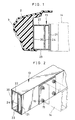
- the bumper assembly includes a bumper reinforcement 1, an energy absorber 2 disposed on the load surface of the bumper reinforcement 1, and a bumper cover 3 covering the energy absorber 2 secured to the bumper reinforcement 1.
- the bumper assembly is secured, at the back face of the bumper reinforcement 1, to a side member 4 constituting part of the vehicle body.
- the bumper reinforcement 1 has a box-shaped configuration comprising a front wall 6 on which the load surface is formed, a rear wall 7 on which the back surface is formed, upper and lower walls 8, 9 connecting the front wall 6 and rear wall 7, and a horizontal intermediate wall 10 connecting the front wall 6 and rear wall 7.
- a problem with this bumper reinforcement 1 is that when the reinforcement is flexed and deformed by a load such as an impact load, a bending moment in a direction which impedes the flexural deformation is produced at the joint between the bumper reinforcement 1 and side member 4, as shown in Fig. 16, since the reinforcement 1 and side member 4 are in a fixed state. As a result, there is the danger that local deformation will occur in the upper and lower walls 8, 9 near the vicinity where the bumper reinforcement 1 is fixed to the side member 4.
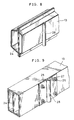
- FIG. 17 An example of the connecting means according to the prior art is shown in Fig. 17. Specifically, a bumper stay 11 secured to the back surface of the bumper reinforcement 1 is fitted into the side member 4, which constitutes part of the vehicle body, and the bumper stay 11 is fixedly connected to the side member 4 by a bolt 12.
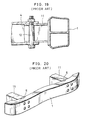
- Another problem encountered in this bumper assembly is that when a load is applied in the direction of the arrow due to a collision or the like, as shown in Fig. 18, the bumper reinforcement 1 attempts to undergo flexural deformation, as indicated by the two-dot chain line, owing to the applied load. Since the bumper stay 11 and side member 4 are in a fixed state, a bending moment in a direction which impedes the flexural deformation is produced at the joint between the bumper stay 11 and side member 4. Consequently, there is the danger that local deformation 5 will occur where the bumper reinforcement 1 is fixed to the bumper stay 11, as illustrated in Figs. 19 and 20.
- an object of the present invention is to provide a bumper assembly in which local deformation of the upper and lower walls of the bumper reinforcement is eliminated.
- Another object of the present invention is to provide a bumper assembly adapted to reduce the bending moment produced in the direction which impedes flexural deformation of the bumper reinforcement.
- a vehicle bumper assembly comprising a pair of side members constituting part of a vehicle body, a bumper reinforcement supported on the side members and extending transversely of the vehicle body, and an energy absorber arranged on a front surface of the bumper reinforcement, the bumper reinforcement having a rectangular cross section, upper and lower walls, and an intermediate wall connecting the upper and lower walls.
- the buckling strength of the upper and lower walls can be increased, thereby making it possible to eliminate local deformation produced, at portions where the upper and lower walls are fixed to the vehicle body, by a bending moment which develops at the joints between the bumper reinforcement and the vehicle body owing to flexural deformation of the bumper reinforcement caused by impact or the like.
- the buckling strength of the upper and lower walls can be increased merely by providing the intermediate wall. As a result, the buckling strength of the upper and lower walls can be raised while maintaining the conventional rigidity of the bumper reinforcement without requiring an increase in the thickness of the upper and lower walls.
- the present invention provides a vehicle bumper assembly comprising a bumper reinforcement extending transversely of a vehicle body, an energy absorber arranged on a load surface of the bumper reinforcement, a bumper cover secured to the bumper reinforcement for covering the energy absorber, and a bumper stay secured to a back surface of the bumper reinforcement for connecting the bumper reinforcement to the vehicle body, the bumper stay having a columnar portion extending vertically of the bumper reinforcement, and the vehicle body having insertion holes matching the columnar portion and a connecting member passed through the columnar portion and the insertion holes for turnably connecting the bumper stay to the vehicle body.
- the bumper assembly according to this aspect of the invention is capable of reducing the bending moment that hinders flexural deformation of the bumper reinforcement produced at the joints between the bumper stay and the vehicle body, thus making it possible to prevent local deformation at portions where the bumper reinforcement is secured to the vehicle body. Since the flexural deformation of the bumper reinforcement can be increased, the energy absorbing capability of the bumper reinforcement is enhanced, thereby reducing the effects of a collision upon the vehicle body.
- the present invention further provides a vehicle bumper assembly comprising a bumper reinforcement extending transversely of a vehicle body, an energy absorber arranged on a load surface of the bumper reinforcement, a bumper cover secured to the bumper reinforcement for covering the energy absorber, the bumper reinforcement having a columnar bumper stay inserted into a through-hole disposed in upper and lower walls in the vicinity of a neutral axis of the bumper reinforcement, and the vehicle body having insertion holes matching a hollow portion of the columnar bumper stay, and a connecting member passed through the hollow portion and the insertion holes for turnably connecting the bumper stay to the vehicle body.
- a compressive load that impedes flexural deformation of the bumper reinforcement can be reduced.
- compressive stress can be reduced at the portions where the bumper reinforcement and bumper stay are fixed and near the center of the load surface of the bumper reinforcement.
- an energy absorber 2 is arranged on a load surface of a bumper reinforcement 13, and the absorber 2 is covered by a bumper cover 3 secured to the bumper reinforcement 13.
- the back surface of the bumper reinforcement 13 is fixedly fastened by a bolt 15 and nut 16 to a side member 14, which constitutes part of a vehicle body (not shown).
- the bumper reinforcement 13 has a box-shaped configuration comprising a front wall 20 on which the load surface is formed, a rear wall 21 on which the back surface is formed, and upper and lower walls 22, 23 connecting the front wall 20 and rear wall 21.
- the bumper reinforcement 13 is provided with an intermediate wall 24, which connects the upper wall 22 and lower wall 23.
- the intermediate wall 24 is located between the front and rear walls 20, 21 but is closer to the rear wall 21. Owing to this construction, the buckling strength of the upper wall 22 and lower wall 23 is raised.
- the buckling strength of the upper and lower walls 22, 23 can be increased merely by providing the intermediate wall 24, the buckling strength of the upper and lower walls 22, 23 can be raised while maintaining the conventional rigidity of the bumper reinforcement 13 without requiring an increase in the thickness of the upper and lower walls 22, 23.
- intermediate wall 24 can be provided substantially midway between the front and rear walls 20, 21, as depicted in Fig. 4.
- the bumper reinforcement 12 has a box-shaped configuration comprising the front wall 20 on which the load surface is formed, the rear wall 21 on which the back surface is formed, and the upper and lower walls 22, 23 connecting the front wall 20 and rear wall 21.
- the bumper reinforcement 13 is provided with the intermediate wall 24, which connects the upper wall 22 and lower wall 23.
- the intermediate wall 24 is located between the front and rear walls 20, 21 but is closer to the front wall 20. Owing to this construction, the buckling strength of the upper wall 22 and lower wall 23 is raised. This makes it possible to prevent local deformation of the upper and lower walls 22, 23 near the central portion of the bumper reinforcement 13 caused by compressive stress that increases due to concentration of load in the bumper reinforcement 13.
- compressive stress itself is capable of being reduced.
- the energy absorber 2 is arranged on the load surface of the bumper reinforcement 13, and the absorber 2 is covered by the bumper cover 3 secured to the bumper reinforcement 13.
- a bumper stay 25 is fastened to the back surface of the bumper reinforcement 13 by a bolt 26 and nut 27.
- a columnar portion 28 is joined as by welding to the bumper stay 25 and extends vertically of the bumper reinforcement 13 (vertically in Figs. 6 and 7).
- the upper and lower sides of a side member 29 constituting part of the vehicle body are formed to include respective flanges 29a that embrace the columnar portion 28 from its upper and lower ends.
- the flanges 29a are formed to have respective insertion holes 30 that match the columnar portion 28.
- a bolt 31 is passed through the columnar portion 28 and insertion holes 30 and is tightened by a nut 32, thereby connecting the bumper stay 25 and the side member 29.
- the bumper stay 25 is capable of turning, relative to the side member 29, about the bolt 31.
- the shape of the bumper reinforcement 13 is not limited to that of the present embodiment. Also, the means for fixing the bumper reinforcement 13 to the bumper stay 25 is not limited to that of the present embodiment.
- the columnar portion 28 can be joined to the bumper reinforcement 13 by being welded directly thereto.
- the columnar portion 28 can be integrated with the bumper stay 25 as by the extrusion molding of aluminum.
- the bumper reinforcement 13 can be assembled as by welding plates, as shown in Fig. 8.
- the bumper stay 25 is turnably connected to the side member 29 by the bolt 31. Therefore, even if the bumper stay 25 attempts to undergo flexural deformation owing to application of a load to the bumper reinforcement 13 by an impact such as a collision, turning of the bumper stay 25 releases this flexural deformation. Consequently, a bending moment that produces flexural deformation of the bumper reinforcement caused at the joints between the bumper stay 25 and the side member 29 can be reduced, thus making it possible to prevent local deformation at portions where the bumper reinforcement 13 is secured to the bumper stay 25. Since the flexural deformation of the bumper reinforcement can be increased, the energy absorbing capability of the bumper reinforcement 13 is enhanced, thereby reducing the effects of a collision upon the vehicle body.
- the energy absorber 2 is arranged on the load surface of a bumper reinforcement 13′, and the absorber 2 is covered by the bumper cover 3 secured to the bumper reinforcement 13′.
- the bumper reinforcement 13′ is formed to have a through-hole 33 in the vicinity of its neutral axis.
- a bumper stay 28 is arranged inside the through-hole 33.
- the bumper stay 28, which is columnar in shape, extends vertically of the bumper reinforcement 13′ (vertically in Figs. 10 and 11) and is formed to have a through-hole.
- the upper and lower sides of the side member 29 constituting part of the vehicle body are formed to include the respective flanges 29a that embrace the bumper stay 28.
- the flanges 29a are formed to have the respective insertion holes 30 that match the through-hole of the columnar portion 28.
- the bolt 31 is passed through this through-hole and the insertion holes 30 and is tightened by a nut 32, thereby connecting the bumper stay 28 and the side member 29.
- the bumper stay 28 is capable of turning, relative to the side member 29, about the bolt 31.
- the shape of the bumper reinforcement 13′ is not limited to that of the present embodiment.
- the through hole of the bumper stay 28 is made a threaded through-hole 140, bolts 170, 171 are screwed into the through-hole 140 from above and below, respectively, and the bolts 170, 171 are tightened.
- the bumper stay 28 comprises coaxially disposed nuts 130, 131. The bolts 170, 171 are screwed into the nuts 130, 131 from above and below, respectively, and the bolts 170, 171 are tightened.
- the bumper stay 28 is disposed near the neutral axis of the bumper reinforcement 13′, stretching of the bumper reinforcement 13′ is facilitated when a load acts upon the bumper reinforcement 13′ and the latter is flexurally deformed owing to impact caused by a collision or the like.
- a compressive load of the kind which hinders flexural deformation of the bumper reinforcement 13′ can be reduced.
- compressive stress at the portions where the bumper reinforcement 13′ is fixed to the bumper stay 28 and near the center of the load surface of the bumper reinforcement 13′ can be reduced, thereby preventing local deformation.
- the bumper stay 28 is turnably connected to the side member 29, flexural deformation of the bumper reinforcement 13′ can be facilitated by this turning motion, and a turning moment which hinders flexural deformation of the bumper reinforcement 13′ can also be reduced. This makes it possible to prevent local deformation, caused by a bending moment, at the portion where the bumper reinforcement 13′ is fixed to the bumper stay 28. Furthermore, since the flexural deformation of the bumper reinforcement 13′ can be increased, the energy absorbing capability of the bumper reinforcement 13′ is enhanced, thereby reducing the effects of a collision upon the vehicle body.
Landscapes
- Engineering & Computer Science (AREA)
- Mechanical Engineering (AREA)
- Body Structure For Vehicles (AREA)
- Vibration Dampers (AREA)
Applications Claiming Priority (8)
| Application Number | Priority Date | Filing Date | Title |
|---|---|---|---|
| JP11105189U JPH0349141U (de) | 1989-09-22 | 1989-09-22 | |
| JP111054/89U | 1989-09-22 | ||
| JP111053/89 | 1989-09-22 | ||
| JP111051/89U | 1989-09-22 | ||
| JP11105489U JPH0349145U (de) | 1989-09-22 | 1989-09-22 | |
| JP11105389U JPH0349146U (de) | 1989-09-22 | 1989-09-22 | |
| JP11105289U JPH0349142U (de) | 1989-09-22 | 1989-09-22 | |
| JP111052/89U | 1989-09-22 |
Publications (2)
| Publication Number | Publication Date |
|---|---|
| EP0418923A1 true EP0418923A1 (de) | 1991-03-27 |
| EP0418923B1 EP0418923B1 (de) | 1994-11-09 |
Family
ID=27469872
Family Applications (1)
| Application Number | Title | Priority Date | Filing Date |
|---|---|---|---|
| EP90118201A Expired - Lifetime EP0418923B1 (de) | 1989-09-22 | 1990-09-21 | Stossfänger für Kraftfahrzeuge |
Country Status (3)
| Country | Link |
|---|---|
| US (1) | US5078439A (de) |
| EP (1) | EP0418923B1 (de) |
| DE (1) | DE69014045T2 (de) |
Cited By (11)
| Publication number | Priority date | Publication date | Assignee | Title |
|---|---|---|---|---|
| WO1996008393A1 (de) * | 1994-09-14 | 1996-03-21 | Pebra Gmbh Paul Braun | Stossfänger für die frontpartie eines strassenfahrzeuges |
| EP0718157A1 (de) * | 1994-12-23 | 1996-06-26 | Alusuisse-Lonza Services AG | Stossstange für Fahrzeuge |
| DE19509541A1 (de) * | 1995-03-16 | 1996-09-19 | Bayerische Motoren Werke Ag | Stoßfänger für ein Kraftfahrzeug |
| DE19545069A1 (de) * | 1995-10-25 | 1997-04-30 | Teves Gmbh Alfred | Stoßstange mit Querträger in Halbschalenbauweise |
| CH688651A5 (de) * | 1994-12-23 | 1997-12-31 | Alusuisse Lonza Services Ag | Stossstange fuer Fahrzeuge. |
| EP0830988A1 (de) * | 1996-08-22 | 1998-03-25 | Bayerische Motoren Werke Aktiengesellschaft, Patentabteilung AJ-3 | Rahmen für ein Fahrzeug |
| EP0734908A3 (de) * | 1995-03-31 | 1998-08-26 | Daimler-Benz Aktiengesellschaft | Stossfänger |
| DE19913078A1 (de) * | 1999-03-23 | 2000-09-28 | Bayerische Motoren Werke Ag | Fahrzeug mit einem Stoßfänger |
| EP1316479A3 (de) * | 2001-11-23 | 2004-06-09 | Dynamit Nobel Kunststoff GmbH | Stossfängerhalter und Stossfänger für Kraftfahrzeuge |
| FR2929223A1 (fr) * | 2008-04-01 | 2009-10-02 | Peugeot Citroen Automobiles Sa | Fixation d'une piece fonctionnelle a une partie de caisse de structure de vehicule. |
| US9415734B2 (en) * | 2015-01-09 | 2016-08-16 | Toyota Motor Engineering & Manufacturing North America, Inc. | Bumper assemblies for vehicles |
Families Citing this family (31)
| Publication number | Priority date | Publication date | Assignee | Title |
|---|---|---|---|---|
| DE4307837B4 (de) * | 1992-03-25 | 2004-12-09 | Volkswagen Ag | Querträgeranordnung, insbesondere zur Aufnahme unfallbedingter Stoßkräfte bei Kraftfahrzeugen |
| US5385375A (en) * | 1992-11-23 | 1995-01-31 | General Motors Corporation | Reinforced impact beam for a bumper assembly and method of manufacture |
| US5545022A (en) * | 1994-02-10 | 1996-08-13 | Shape Corporation | Apparatus for manufacturing a vehicle bumper |
| US5658027A (en) * | 1995-10-03 | 1997-08-19 | Ford Global Tech Inc | Blow molded vehicle bumper system in method |
| NO964154L (no) * | 1996-10-01 | 1998-04-02 | Hydro Raufoss Automotive As | Fremgangsmåte for fremstilling av en konstruksjonsdel |
| NO974375L (no) * | 1997-09-22 | 1999-03-23 | Norsk Hydro As | St°tfanger, samt tilvirkning av samme |
| DE19745651C2 (de) * | 1997-10-16 | 2000-04-27 | Daimler Chrysler Ag | Pralldämpfer für ein Kraftfahrzeug |
| US6485072B1 (en) | 1999-12-15 | 2002-11-26 | Ford Global Technologies, Inc. | Bumper system for motor vehicles |
| US6406077B2 (en) | 2000-05-11 | 2002-06-18 | Shape Corporation | Tube with extruded flanges holding wall-reinforcing insert |
| US6412836B1 (en) | 2000-10-11 | 2002-07-02 | Ford Global Technologies, Inc. | Bumper system for motor vehicles |
| ES2302720T3 (es) * | 2001-02-21 | 2008-08-01 | ALCAN TECHNOLOGY & MANAGEMENT AG | Vehiculo con parachoques y elemento de deformacion. |
| US6814381B1 (en) * | 2001-02-21 | 2004-11-09 | Alcan Technology & Management Ltd. | Vehicle with bumper and deformation element |
| US6428064B1 (en) * | 2001-03-13 | 2002-08-06 | Ford Global Technologies, Inc. | Energy absorbing bumper |
| ITMI20011170A1 (it) * | 2001-06-01 | 2002-12-01 | Adlev Srl | Struttura di protezione per veicoli, atta ad essere utilizzata, in particolare, nel caso di urti con pedoni |
| ITMI20011192A1 (it) * | 2001-06-06 | 2002-12-06 | Adlev Srl | Struttura di protezione per veicoli |
| US6416094B1 (en) * | 2001-07-27 | 2002-07-09 | Talfourd-Jones Inc. | Energy absorbing bumper |
| FR2829734B1 (fr) * | 2001-09-20 | 2004-01-23 | Peguform France | Poutre de pare-chocs pour vehicule comprenantune traversee et deux absorbeurs de chocs |
| DE10248637A1 (de) * | 2002-10-18 | 2004-05-06 | Dr.Ing.H.C. F. Porsche Ag | Stoßfänger für ein Kraftfahrzeug |
| US7165794B2 (en) * | 2002-11-19 | 2007-01-23 | Compagnie Plastic Omnium | Passive safety device |
| DE102004016839B4 (de) * | 2004-04-01 | 2011-04-28 | Ise Automotive Gmbh | Vorrichtung zur Aufnahme von Stoßenergie |
| US7975383B2 (en) * | 2006-07-28 | 2011-07-12 | Ford Global Technologies, Llc | Double hydroformed tube with integral reinforcement |
| DE102007039211A1 (de) * | 2007-08-20 | 2009-02-26 | Volkswagen Ag | Stoßfänger für Kraftfahrzeuge |
| US7866716B2 (en) * | 2008-04-08 | 2011-01-11 | Flex-N-Gate Corporation | Energy absorber for vehicle |
| US7758107B2 (en) * | 2008-07-29 | 2010-07-20 | Ford Global Technologies, Llc | Dual cell body side rail for automotive vehicles |
| DE102010050960A1 (de) * | 2010-11-10 | 2012-05-10 | Gm Global Technology Operations Llc (N.D.Ges.D. Staates Delaware) | Stoßfängerquerträger für ein Kraftfahrzeug, Verstärkungsbauteil für einen Stoßfängerquerträger und Verfahren zur Herstellung eines Stoßfängerquerträgers |
| US9505361B2 (en) | 2013-10-04 | 2016-11-29 | Multimatic Inc. | Vehicle bumper |
| GB2519810A (en) * | 2013-10-31 | 2015-05-06 | Gm Global Tech Operations Inc | Vehicle front structure |
| JP2015182704A (ja) * | 2014-03-26 | 2015-10-22 | アイシン精機株式会社 | バンパーリインフォースメント |
| DE102015121152B4 (de) | 2015-10-26 | 2021-01-14 | Benteler Automobiltechnik Gmbh | Stoßfängeranordnung für ein Kraftfahrzeug |
| US10065587B2 (en) | 2015-11-23 | 2018-09-04 | Flex|N|Gate Corporation | Multi-layer energy absorber |
| DE102018119735B4 (de) * | 2018-08-14 | 2024-06-27 | Kirchhoff Automotive Deutschland Gmbh | Stoßfängerquerträger für ein Kraftfahrzeug |
Citations (3)
| Publication number | Priority date | Publication date | Assignee | Title |
|---|---|---|---|---|
| US3850466A (en) * | 1972-08-14 | 1974-11-26 | A Yepis | Vehicle bumper and frame mounting |
| DE3035176A1 (de) * | 1980-09-18 | 1982-04-22 | Volkswagenwerk Ag, 3180 Wolfsburg | Kraftfahrzeug mit einer als stossschutz dienenden softnose |
| DE3144844A1 (de) * | 1980-11-14 | 1982-06-03 | Aisin Seiki K.K., Kariya, Aichi | "verstaerkungsbauteil fuer einen stossfaenger eines kraftfahrzeuges" |
Family Cites Families (14)
| Publication number | Priority date | Publication date | Assignee | Title |
|---|---|---|---|---|
| US4018466A (en) * | 1970-04-20 | 1977-04-19 | Saab-Scania Aktiebolag | Vehicle bumper assembly |
| US3741560A (en) * | 1971-09-01 | 1973-06-26 | Gen Motors Corp | Dampened shock absorbing bumper |
| DE2255277A1 (de) * | 1972-11-11 | 1974-05-22 | Volkswagenwerk Ag | Stosstange, insbesondere fuer kraftfahrzeuge |
| US3933387A (en) * | 1975-03-10 | 1976-01-20 | General Motors Corporation | Thermoformed plastic energy absorber for vehicles |
| US4072334A (en) * | 1975-07-21 | 1978-02-07 | Energy Absorption Systems, Inc. | Energy absorbing bumper |
| JPS5531A (en) * | 1978-05-26 | 1980-01-05 | Kobayashi Cutlery Mfg | Running wheel device on tea harvester |
| JPS5915180A (ja) * | 1982-07-13 | 1984-01-26 | 日産自動車株式会社 | スライドドア車におけるガイドレ−ルの支持構造 |
| JPS5985759A (ja) * | 1982-11-09 | 1984-05-17 | Komori Printing Mach Co Ltd | 反転機構付枚葉輪転印刷機 |
| JPS62128852A (ja) * | 1985-11-29 | 1987-06-11 | Honda Motor Co Ltd | 自動車用合成樹脂製バンパ |
| JPS638046A (ja) * | 1986-06-27 | 1988-01-13 | Tonen Sekiyukagaku Kk | 自動車用バンパ− |
| JPS6340257U (de) * | 1986-09-02 | 1988-03-16 | ||
| US4826238A (en) * | 1986-12-01 | 1989-05-02 | Honda Giken Kogyo Kabushiki Kaisha | Side sill for automotive vehicle |
| US4909565A (en) * | 1987-04-17 | 1990-03-20 | Mazda Motor Corporation | Front body construction |
| US4910938A (en) * | 1988-12-20 | 1990-03-27 | Porta-Fab Corporation | Wall stud for portable/in-plant building |
-
1990
- 1990-09-18 US US07/583,973 patent/US5078439A/en not_active Expired - Fee Related
- 1990-09-21 DE DE69014045T patent/DE69014045T2/de not_active Expired - Fee Related
- 1990-09-21 EP EP90118201A patent/EP0418923B1/de not_active Expired - Lifetime
Patent Citations (3)
| Publication number | Priority date | Publication date | Assignee | Title |
|---|---|---|---|---|
| US3850466A (en) * | 1972-08-14 | 1974-11-26 | A Yepis | Vehicle bumper and frame mounting |
| DE3035176A1 (de) * | 1980-09-18 | 1982-04-22 | Volkswagenwerk Ag, 3180 Wolfsburg | Kraftfahrzeug mit einer als stossschutz dienenden softnose |
| DE3144844A1 (de) * | 1980-11-14 | 1982-06-03 | Aisin Seiki K.K., Kariya, Aichi | "verstaerkungsbauteil fuer einen stossfaenger eines kraftfahrzeuges" |
Cited By (12)
| Publication number | Priority date | Publication date | Assignee | Title |
|---|---|---|---|---|
| WO1996008393A1 (de) * | 1994-09-14 | 1996-03-21 | Pebra Gmbh Paul Braun | Stossfänger für die frontpartie eines strassenfahrzeuges |
| EP0718157A1 (de) * | 1994-12-23 | 1996-06-26 | Alusuisse-Lonza Services AG | Stossstange für Fahrzeuge |
| CH688651A5 (de) * | 1994-12-23 | 1997-12-31 | Alusuisse Lonza Services Ag | Stossstange fuer Fahrzeuge. |
| DE19509541A1 (de) * | 1995-03-16 | 1996-09-19 | Bayerische Motoren Werke Ag | Stoßfänger für ein Kraftfahrzeug |
| EP0734908A3 (de) * | 1995-03-31 | 1998-08-26 | Daimler-Benz Aktiengesellschaft | Stossfänger |
| DE19545069A1 (de) * | 1995-10-25 | 1997-04-30 | Teves Gmbh Alfred | Stoßstange mit Querträger in Halbschalenbauweise |
| DE19545069B4 (de) * | 1995-10-25 | 2007-04-12 | Automotive Group Ise Innomotive Systems Europe Gmbh | Stoßstange mit Querträger in Halbschalenbauweise |
| EP0830988A1 (de) * | 1996-08-22 | 1998-03-25 | Bayerische Motoren Werke Aktiengesellschaft, Patentabteilung AJ-3 | Rahmen für ein Fahrzeug |
| DE19913078A1 (de) * | 1999-03-23 | 2000-09-28 | Bayerische Motoren Werke Ag | Fahrzeug mit einem Stoßfänger |
| EP1316479A3 (de) * | 2001-11-23 | 2004-06-09 | Dynamit Nobel Kunststoff GmbH | Stossfängerhalter und Stossfänger für Kraftfahrzeuge |
| FR2929223A1 (fr) * | 2008-04-01 | 2009-10-02 | Peugeot Citroen Automobiles Sa | Fixation d'une piece fonctionnelle a une partie de caisse de structure de vehicule. |
| US9415734B2 (en) * | 2015-01-09 | 2016-08-16 | Toyota Motor Engineering & Manufacturing North America, Inc. | Bumper assemblies for vehicles |
Also Published As
| Publication number | Publication date |
|---|---|
| US5078439A (en) | 1992-01-07 |
| DE69014045T2 (de) | 1995-03-30 |
| EP0418923B1 (de) | 1994-11-09 |
| DE69014045D1 (de) | 1994-12-15 |
Similar Documents
| Publication | Publication Date | Title |
|---|---|---|
| US5078439A (en) | Bumper assembly for vehicles | |
| US5609004A (en) | End part for a vehicle longitudinal beam | |
| US4348042A (en) | Vehicle bumper assembly | |
| CA2386494C (en) | Automobile body structure | |
| US6250710B1 (en) | Front body structure of vehicle | |
| CN1138658C (zh) | 挤压件的连接构造 | |
| US6499798B2 (en) | Vehicle body structure | |
| US6866333B2 (en) | Vehicle front body structure | |
| JPH0375386B2 (de) | ||
| KR20010063128A (ko) | 자동차용 프레임의 보강을 위한 보강재 | |
| US4783104A (en) | Bumper assembly | |
| KR100385283B1 (ko) | 차량의 프레임 연결부 구조물 | |
| JPH1081259A (ja) | サイドメンバ補強構造 | |
| JP3438542B2 (ja) | バンパリインフォースメント取付構造 | |
| JP3275651B2 (ja) | ステアリングメンバの取付構造 | |
| JP2004306776A (ja) | 自動車のトレーラヒッチ装置 | |
| JP3181792B2 (ja) | 自動車車体のサイドフレームとクロスメンバとの結合部構造 | |
| JP3223733B2 (ja) | 自動車用バンパ | |
| JPH0541994U (ja) | トラツク用バンパー | |
| JPH0750305Y2 (ja) | 自動車のフロントフロア構造 | |
| CN218229163U (zh) | 一种车辆的后地板加强结构及车辆 | |
| JPH0433170Y2 (de) | ||
| JPH08230588A (ja) | 自動車用バンパー取り付け金具 | |
| JPH052366Y2 (de) | ||
| JP3362915B2 (ja) | 自動車の前部車体構造 |
Legal Events
| Date | Code | Title | Description |
|---|---|---|---|
| PUAI | Public reference made under article 153(3) epc to a published international application that has entered the european phase |
Free format text: ORIGINAL CODE: 0009012 |
|
| AK | Designated contracting states |
Kind code of ref document: A1 Designated state(s): DE FR GB |
|
| 17P | Request for examination filed |
Effective date: 19910503 |
|
| 17Q | First examination report despatched |
Effective date: 19921008 |
|
| GRAA | (expected) grant |
Free format text: ORIGINAL CODE: 0009210 |
|
| AK | Designated contracting states |
Kind code of ref document: B1 Designated state(s): DE FR GB |
|
| REF | Corresponds to: |
Ref document number: 69014045 Country of ref document: DE Date of ref document: 19941215 |
|
| ET | Fr: translation filed | ||
| PLBE | No opposition filed within time limit |
Free format text: ORIGINAL CODE: 0009261 |
|
| STAA | Information on the status of an ep patent application or granted ep patent |
Free format text: STATUS: NO OPPOSITION FILED WITHIN TIME LIMIT |
|
| 26N | No opposition filed | ||
| PGFP | Annual fee paid to national office [announced via postgrant information from national office to epo] |
Ref country code: FR Payment date: 19990909 Year of fee payment: 10 |
|
| PGFP | Annual fee paid to national office [announced via postgrant information from national office to epo] |
Ref country code: GB Payment date: 19990915 Year of fee payment: 10 |
|
| PGFP | Annual fee paid to national office [announced via postgrant information from national office to epo] |
Ref country code: DE Payment date: 19990927 Year of fee payment: 10 |
|
| PG25 | Lapsed in a contracting state [announced via postgrant information from national office to epo] |
Ref country code: GB Free format text: LAPSE BECAUSE OF NON-PAYMENT OF DUE FEES Effective date: 20000921 |
|
| GBPC | Gb: european patent ceased through non-payment of renewal fee |
Effective date: 20000921 |
|
| PG25 | Lapsed in a contracting state [announced via postgrant information from national office to epo] |
Ref country code: FR Free format text: LAPSE BECAUSE OF NON-PAYMENT OF DUE FEES Effective date: 20010531 |
|
| PG25 | Lapsed in a contracting state [announced via postgrant information from national office to epo] |
Ref country code: DE Free format text: LAPSE BECAUSE OF NON-PAYMENT OF DUE FEES Effective date: 20010601 |
|
| REG | Reference to a national code |
Ref country code: FR Ref legal event code: ST |