EP0419008B1 - Système de siège pour vanne - Google Patents
Système de siège pour vanne Download PDFInfo
- Publication number
- EP0419008B1 EP0419008B1 EP90307783A EP90307783A EP0419008B1 EP 0419008 B1 EP0419008 B1 EP 0419008B1 EP 90307783 A EP90307783 A EP 90307783A EP 90307783 A EP90307783 A EP 90307783A EP 0419008 B1 EP0419008 B1 EP 0419008B1
- Authority
- EP
- European Patent Office
- Prior art keywords
- seat
- gate
- sealing
- ring
- cavity
- Prior art date
- Legal status (The legal status is an assumption and is not a legal conclusion. Google has not performed a legal analysis and makes no representation as to the accuracy of the status listed.)
- Expired - Lifetime
Links
Images

Classifications
-
- F—MECHANICAL ENGINEERING; LIGHTING; HEATING; WEAPONS; BLASTING
- F16—ENGINEERING ELEMENTS AND UNITS; GENERAL MEASURES FOR PRODUCING AND MAINTAINING EFFECTIVE FUNCTIONING OF MACHINES OR INSTALLATIONS; THERMAL INSULATION IN GENERAL
- F16K—VALVES; TAPS; COCKS; ACTUATING-FLOATS; DEVICES FOR VENTING OR AERATING
- F16K3/00—Gate valves or sliding valves, i.e. cut-off apparatus with closing members having a sliding movement along the seat for opening and closing
- F16K3/02—Gate valves or sliding valves, i.e. cut-off apparatus with closing members having a sliding movement along the seat for opening and closing with flat sealing faces; Packings therefor
- F16K3/0227—Packings
- F16K3/0236—Packings the packing being of a non-resilient material, e.g. ceramic, metal
Definitions
- Gate valves generally comprise a body furnished with an internal gate cavity positioned generally perpendicular to a flow bore which extends through the body communicating the cavity to the inlet and outlet bores.
- a gate is positioned in this cavity, the gate being movable by external means. With the gate in its closed position flow between the inlet and outlet bores is sealed and with the gate in its open position full bore flow is allowed.
- Gate valves are known which have seat mechanisms either side of the gate which engage the body surfaces surrounding the inlet and outlet flow bores through the body together with gate sealing faces. Such seats are generally disposed in annular recesses known as seat pockets provided in the around the inlet and outlet bores at positions where they communicate with the gate cavity.
- Another arrangement uses inner and outer metallic sealing rings, such as metal C-ring seals, located in inner and outer grooves on an end face of the seat and the seat is locked in position in its recess by means of a locking ring which engages an outer circumferential surface of the seat, the locking ring itself being held in position by a retainer wire.
- the locking ring is used to load the seat against the body energising the C-ring seals, effecting a seat/body seal.
- GB-A-2034009 and US-A-3006599 each discloses a gate valve comprising a body having a gate cavity and a flowbore extending through the body and opening into the gate cavity, a recess around each of the openings of the flowbore to the gate cavity, and a respective seat mechanism disposed in each recess, sealing means associated with each seat mechanism for sealing against a body sealing surface, and a gate positioned in the cavity between the seat mechanisms and movable to open and seal a flow path through the flowbore, wherein each seat mechanism comprises an assembly which by means of a disc spring energises the sealing means to provide a seal between the seat and the body sealing surface.
- the present invention is concerned with an improved seat mechanism for a gate valve of the aforementioned type.
- such a gate valve is characterised in that each disc spring is retained against a profile on the valve seat by a loading ring disposed around the seat ring and a retainer ring located in an annular groove formed in the wall of the recess. This arrangement facilitates the assembly of the seat mechanism.
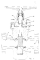
- a gate valve comprises a body (12) having an inlet (14) and an outlet (16) which communicates with a gate cavity (18).
- a one piece slab gate (20) is disposed within this cavity (18) and is movable via a stem (22) upwardly and downwardly by suitable actuating means, between a position in which it allows fluid to flow between the inlet and outlets (14, 16) and a position in which it closes and hence seals the flow.
- a bonnet (24) is secured to the body (12).
- the stem (22) extends upwardly through the bonnet (24) and is sealed therein by a sealing assembly (30).
- each seat pocket has a larger diameter portion (41) which extends from the gate cavity (18) over a substantial portion of the axial extent of the recess and a smaller diameter portion (43), which terminates at a body sealing surface (46).
- the wall of the larger diameter (41) is formed with a square sectioned, intermittently cut, annular groove (47).
- Each seat is annular and has a major portion (44) which is located in the recess (41) and protrudes into the cavity (18) to a position adjacent the gate (20) and a larger diameter portion (49) near its junction with the body sealing surface (46).
- An annular shoulder (51) is formed at the junction of the seat portion (44 and 49).
- the end face of the seat which is adjacent to the body sealing surface (46) has inner and outer annular grooves (48, 50). Each annular groove accommodates a metal uni-directional C-ring seal (52, 54).
- An assembly (60) for biassing the seals (52 and 54) into sealing engagement with the body sealing surface (46) is located around the outer periphery of the seat (42) within the seat pocket (40).
- This assembly comprises a disc or beville type spring (62) which abuts the seats shoulder (51), an annular load ring (64) and a split retainer ring (66) which is located in the annular groove (47) formed in the circumferential wall of the recess.
- the spring 62 can be made of Inconel (trade mark).
- the spring force generated by the disc spring (62) is sufficient to hold the seat (42) in permanent contact with the body sealing surface (46) at all times, energising the metal C-rings (52, 54) thereby generating metal-to-metal sealing between the seat and the body sealing surface.
- This method of sealing also prevents intrusion of particulate contamination between the seat and body surfaces, which if allowed could lead to pitting and finally washout leakage.
- Strategical positioning of the C-rings ensures no separation of seat and body during valve operation, any pressure fluctations in the value biassing the seat (42) into the seat pocket even in the event of the unlikely breakdown of the C-ring seals.
- a raised lip (72) is formed at the inner edge of the inner groove (48) on the seat (42). This lip gives added support to the inner C-ring seat (52) if subjected to reverse pressure.
- the opposite end sealing surface (70) of the valve seat relies on good surface finish and flatness properties to provide metal-to-metal sealing with the gate (20) when the gate is moved to its closed position.
- the inlet and outlet seat members are located in their respective seat pockets.
- neither the gate (20), stem (22) or bonnet (24) are in position.
- the disc spring (62), load ring (64) and retainer ring (66) are then located around the outer periphery of the seat and forced against the seat shoulder (51) by means of a hydraulic jacking tool.
- the retainer ring (66) is snapped outwardly by means of an appropriate tool into the groove (47) formed in the circumferential wall of the recess in the body.
- the jacking tool load is then released leaving the mechanism in a fully locked-in condition.
- the same procedure is then performed on the opposite side after which the gate may be installed.
Landscapes
- Engineering & Computer Science (AREA)
- General Engineering & Computer Science (AREA)
- Ceramic Engineering (AREA)
- Mechanical Engineering (AREA)
- Sliding Valves (AREA)
- Toilet Supplies (AREA)
- Pens And Brushes (AREA)
- Braking Systems And Boosters (AREA)
- Magnetically Actuated Valves (AREA)
- Fluid-Driven Valves (AREA)
- Electrically Driven Valve-Operating Means (AREA)
- Mechanically-Actuated Valves (AREA)
- Fluid-Damping Devices (AREA)
Claims (3)
- Robinet-vanne comprenant un corps (12) comportant une cavité d'obturateur (18) et un passage d'écoulement (14, 16) traversant le corps et débouchant dans la cavité d'obturateur, un évidement (40) ménagé autour de chacun des orifices par lesquels le passage d'écoulement débouche dans la cavité d'obturateur, un mécanisme de siège (42) respectif, disposé dans chaque évidement, des moyens d'étanchéité (52, 54), associés à chaque mécanisme de siège pour assurer l'étanchéité sur une surface d'étanchéité du corps, et un obturateur (20) disposé dans la cavité entre les mécanismes de siège et mobile de façon à ouvrir et obturer un trajet d'écoulement par le passage d'écoulement, tandis que chaque mécanisme de siège comprend un ensemble qui, au moyen d'une rondelle Belleville (62), met en service les moyens d'étanchéité (52, 54) de façon à assurer une étanchéité entre le siège (42) et la surface d'étanchéité (46) du corps, caractérisé en ce que chaque rondelle Belleville (62) est maintenue contre une partie profilée (51), ménagée sur le siège d'obturateur, au moyen d'une bague de mise en charge (64), disposée autour de la bague de siège, et d'une bague de retenue (66) disposée dans une gorge annulaire ménagée dans la paroi de l'évidement.
- Robinet-vanne suivant la revendication 1, dans lequel les moyens d'étanchéité comprennent des bagues d'étanchéité intérieure et extérieure (52, 54) disposées dans des gorges intérieure et extérieure ménagées sur la face extérieure de la bague de siège qui est disposée en appui contre la surface d'étanchéité du corps.
- Robinet-vanne suivant la revendication 2, dans lequel les bagues annulaires d'étanchéité (52, 54) sont des bagues métalliques annulaires d'étanchéité en C.
Priority Applications (1)
| Application Number | Priority Date | Filing Date | Title |
|---|---|---|---|
| AT9090307783T ATE104754T1 (de) | 1989-08-18 | 1990-07-17 | Ventilsitzmechanismus. |
Applications Claiming Priority (2)
| Application Number | Priority Date | Filing Date | Title |
|---|---|---|---|
| GB898918842A GB8918842D0 (en) | 1989-08-18 | 1989-08-18 | Valve seat mechanism |
| GB8918842 | 1989-08-18 |
Publications (2)
| Publication Number | Publication Date |
|---|---|
| EP0419008A1 EP0419008A1 (fr) | 1991-03-27 |
| EP0419008B1 true EP0419008B1 (fr) | 1994-04-20 |
Family
ID=10661809
Family Applications (1)
| Application Number | Title | Priority Date | Filing Date |
|---|---|---|---|
| EP90307783A Expired - Lifetime EP0419008B1 (fr) | 1989-08-18 | 1990-07-17 | Système de siège pour vanne |
Country Status (8)
| Country | Link |
|---|---|
| US (1) | US5029812A (fr) |
| EP (1) | EP0419008B1 (fr) |
| JP (1) | JPH0389082A (fr) |
| AT (1) | ATE104754T1 (fr) |
| CA (1) | CA2021962C (fr) |
| DE (1) | DE69008287T2 (fr) |
| GB (1) | GB8918842D0 (fr) |
| NO (1) | NO176115C (fr) |
Families Citing this family (19)
| Publication number | Priority date | Publication date | Assignee | Title |
|---|---|---|---|---|
| US6260822B1 (en) * | 2000-01-04 | 2001-07-17 | Worldwide Oilfield Machine, Inc | Seat assembly for a gate valve |
| US6401747B1 (en) | 2000-07-13 | 2002-06-11 | Fmc Corporation | Gate valve |
| US6664572B2 (en) * | 2001-07-23 | 2003-12-16 | Hp&T Products, Inc. | Valve seal assemblies and methods |
| KR20020071487A (ko) * | 2002-05-22 | 2002-09-12 | 홍광의 | 중장비의 압축 및 선별용 작업 장치 |
| US7004452B2 (en) * | 2003-09-25 | 2006-02-28 | Hp&T Products, Inc. | Valve seal assemblies and methods |
| CA2515906C (fr) * | 2004-08-20 | 2013-05-28 | Stream-Flo Industries Ltd. | Robinet-vanne avec joint a emboitement male et femelle ou joint de pontage de siege annulaire |
| US7562859B2 (en) | 2004-08-20 | 2009-07-21 | Stream-Flo Industries Ltd. | Gate valve with tongue and groove or bridging seal to annular seat elements |
| CN103038551B (zh) * | 2009-08-12 | 2014-10-08 | 通用电气石油和天然气压力控制有限公司 | 闸阀底座 |
| GB2485198B (en) * | 2010-11-05 | 2015-05-27 | Aker Subsea Ltd | Subsea valve seat arrangements |
| US20130119288A1 (en) * | 2011-11-16 | 2013-05-16 | Vetco Gray Inc. | Gate shear valve |
| US9453578B2 (en) | 2013-07-08 | 2016-09-27 | Alagarsamy Sundararajan | Gate valve with seat assembly |
| US9447909B2 (en) * | 2013-08-08 | 2016-09-20 | Chromatic Industries, Inc. | Connector assembly usable as a closure and to establish a fluid connection |
| CN103968095A (zh) * | 2014-05-19 | 2014-08-06 | 江苏金石科技有限公司 | 金属密封热采手动平板闸阀 |
| US9885420B2 (en) | 2015-05-07 | 2018-02-06 | Sri Energy, Inc. | Gate valve |
| US10914387B2 (en) * | 2016-04-20 | 2021-02-09 | Fisher Controls International Llc | Rotary control valve having a clamped valve seat |
| US12259064B2 (en) | 2018-11-01 | 2025-03-25 | Oil States Energy Services, L.L.C. | Valve with pressure differential seating |
| US11499644B2 (en) | 2020-08-25 | 2022-11-15 | Emerson Automation Solutions Final Control US LP | Sealing assembly for a knife gate valve |
| US11300213B1 (en) | 2021-02-19 | 2022-04-12 | Emerson Automation Solutions Final Control US LP | Floating yoke connection |
| US20250035219A1 (en) * | 2022-06-28 | 2025-01-30 | Zp Interests, Llc | Pressure energized gate valve seat and seal assembly |
Family Cites Families (4)
| Publication number | Priority date | Publication date | Assignee | Title |
|---|---|---|---|---|
| US3006599A (en) * | 1959-07-20 | 1961-10-31 | Acf Ind Inc | Valve seat |
| US4264054A (en) * | 1978-10-30 | 1981-04-28 | Mcevoy Oilfield Equipment Company | Metal-to-metal seat hub seals |
| US4629161A (en) * | 1985-05-02 | 1986-12-16 | Cameron Iron Works, Inc. | Gate valve |
| US4741509A (en) * | 1987-02-19 | 1988-05-03 | Cameron Iron Works, Inc. | Gate valve with improved secondary body to bushing seals |
-
1989
- 1989-08-18 GB GB898918842A patent/GB8918842D0/en active Pending
-
1990
- 1990-07-13 US US07/553,447 patent/US5029812A/en not_active Expired - Fee Related
- 1990-07-17 DE DE69008287T patent/DE69008287T2/de not_active Expired - Fee Related
- 1990-07-17 AT AT9090307783T patent/ATE104754T1/de not_active IP Right Cessation
- 1990-07-17 EP EP90307783A patent/EP0419008B1/fr not_active Expired - Lifetime
- 1990-07-24 NO NO903289A patent/NO176115C/no unknown
- 1990-07-25 CA CA002021962A patent/CA2021962C/fr not_active Expired - Fee Related
- 1990-08-14 JP JP2215695A patent/JPH0389082A/ja active Pending
Also Published As
| Publication number | Publication date |
|---|---|
| CA2021962A1 (fr) | 1991-02-19 |
| JPH0389082A (ja) | 1991-04-15 |
| DE69008287D1 (de) | 1994-05-26 |
| NO176115B (no) | 1994-10-24 |
| US5029812A (en) | 1991-07-09 |
| NO903289D0 (no) | 1990-07-24 |
| CA2021962C (fr) | 1994-10-25 |
| NO903289L (no) | 1991-02-19 |
| EP0419008A1 (fr) | 1991-03-27 |
| GB8918842D0 (en) | 1989-09-27 |
| DE69008287T2 (de) | 1994-10-20 |
| ATE104754T1 (de) | 1994-05-15 |
| NO176115C (no) | 1995-02-01 |
Similar Documents
| Publication | Publication Date | Title |
|---|---|---|
| EP0419008A1 (fr) | Système de siège pour vanne | |
| US3078865A (en) | Self sealing gate valve | |
| CA2980589C (fr) | Manchon protecteur de robinet-vanne | |
| US2713989A (en) | Valve construction | |
| US3379405A (en) | Valve | |
| US4113268A (en) | Extended temperature range valve seal | |
| EP0573399B1 (fr) | Siège d'étanchéité pour vannes du type ANSI classe V | |
| US4471943A (en) | Valve assembly and seat | |
| US4625942A (en) | Valve assembly, seat and seal | |
| US4302020A (en) | Actuating sealing joint | |
| US7249750B2 (en) | Pressure balanced fluid control device | |
| US4682757A (en) | Secondary backseat for gate valve | |
| WO2013103715A1 (fr) | Goupille de retenue du siège de soupape | |
| GB2566778A (en) | Gate valve with retainer | |
| US5192051A (en) | Unidirectional seat seal for gate valve | |
| US3412756A (en) | Poppet valve having oppositely directed spherical seating surfaces | |
| GB2034009A (en) | Metal-to-metal seat hub seals | |
| US5083582A (en) | Valve with removable insert | |
| EP0211470B1 (fr) | Robinet à tiroir | |
| USRE29299E (en) | Self sealing gate valve | |
| WO1992018365A1 (fr) | Structure de soupape de commande | |
| US7309058B2 (en) | Flexible backseat seal for gate valve | |
| EP0426915B1 (fr) | Vanne comportant une pièce d'insertion amovible | |
| GB2266576A (en) | Selective double backseat for valve stems | |
| US5127629A (en) | Valve stem flex lip backseat |
Legal Events
| Date | Code | Title | Description |
|---|---|---|---|
| PUAI | Public reference made under article 153(3) epc to a published international application that has entered the european phase |
Free format text: ORIGINAL CODE: 0009012 |
|
| AK | Designated contracting states |
Kind code of ref document: A1 Designated state(s): AT DE FR GB NL |
|
| 17P | Request for examination filed |
Effective date: 19910828 |
|
| 17Q | First examination report despatched |
Effective date: 19930114 |
|
| GRAA | (expected) grant |
Free format text: ORIGINAL CODE: 0009210 |
|
| AK | Designated contracting states |
Kind code of ref document: B1 Designated state(s): AT DE FR GB NL |
|
| REF | Corresponds to: |
Ref document number: 104754 Country of ref document: AT Date of ref document: 19940515 Kind code of ref document: T |
|
| REF | Corresponds to: |
Ref document number: 69008287 Country of ref document: DE Date of ref document: 19940526 |
|
| ET | Fr: translation filed | ||
| PLBE | No opposition filed within time limit |
Free format text: ORIGINAL CODE: 0009261 |
|
| STAA | Information on the status of an ep patent application or granted ep patent |
Free format text: STATUS: NO OPPOSITION FILED WITHIN TIME LIMIT |
|
| 26N | No opposition filed | ||
| PGFP | Annual fee paid to national office [announced via postgrant information from national office to epo] |
Ref country code: GB Payment date: 19950619 Year of fee payment: 6 |
|
| PGFP | Annual fee paid to national office [announced via postgrant information from national office to epo] |
Ref country code: AT Payment date: 19950621 Year of fee payment: 6 |
|
| PGFP | Annual fee paid to national office [announced via postgrant information from national office to epo] |
Ref country code: NL Payment date: 19950707 Year of fee payment: 6 |
|
| PGFP | Annual fee paid to national office [announced via postgrant information from national office to epo] |
Ref country code: FR Payment date: 19950714 Year of fee payment: 6 |
|
| PGFP | Annual fee paid to national office [announced via postgrant information from national office to epo] |
Ref country code: DE Payment date: 19950731 Year of fee payment: 6 |
|
| REG | Reference to a national code |
Ref country code: GB Ref legal event code: 732E |
|
| PG25 | Lapsed in a contracting state [announced via postgrant information from national office to epo] |
Ref country code: GB Effective date: 19960717 Ref country code: AT Effective date: 19960717 |
|
| PG25 | Lapsed in a contracting state [announced via postgrant information from national office to epo] |
Ref country code: NL Effective date: 19970201 |
|
| GBPC | Gb: european patent ceased through non-payment of renewal fee |
Effective date: 19960717 |
|
| PG25 | Lapsed in a contracting state [announced via postgrant information from national office to epo] |
Ref country code: FR Effective date: 19970328 |
|
| NLV4 | Nl: lapsed or anulled due to non-payment of the annual fee |
Effective date: 19970201 |
|
| PG25 | Lapsed in a contracting state [announced via postgrant information from national office to epo] |
Ref country code: DE Effective date: 19970402 |
|
| REG | Reference to a national code |
Ref country code: FR Ref legal event code: ST |