EP0419019B1 - Système de contrôle du routage de messages - Google Patents
Système de contrôle du routage de messages Download PDFInfo
- Publication number
- EP0419019B1 EP0419019B1 EP90308558A EP90308558A EP0419019B1 EP 0419019 B1 EP0419019 B1 EP 0419019B1 EP 90308558 A EP90308558 A EP 90308558A EP 90308558 A EP90308558 A EP 90308558A EP 0419019 B1 EP0419019 B1 EP 0419019B1
- Authority
- EP
- European Patent Office
- Prior art keywords
- message
- message identity
- incoming
- outgoing
- identity portion
- Prior art date
- Legal status (The legal status is an assumption and is not a legal conclusion. Google has not performed a legal analysis and makes no representation as to the accuracy of the status listed.)
- Expired - Lifetime
Links
Images

Classifications
-
- H—ELECTRICITY
- H04—ELECTRIC COMMUNICATION TECHNIQUE
- H04Q—SELECTING
- H04Q11/00—Selecting arrangements for multiplex systems
- H04Q11/04—Selecting arrangements for multiplex systems for time-division multiplexing
-
- H—ELECTRICITY
- H04—ELECTRIC COMMUNICATION TECHNIQUE
- H04L—TRANSMISSION OF DIGITAL INFORMATION, e.g. TELEGRAPHIC COMMUNICATION
- H04L49/00—Packet switching elements
- H04L49/55—Prevention, detection or correction of errors
- H04L49/555—Error detection
-
- H—ELECTRICITY
- H04—ELECTRIC COMMUNICATION TECHNIQUE
- H04L—TRANSMISSION OF DIGITAL INFORMATION, e.g. TELEGRAPHIC COMMUNICATION
- H04L9/00—Cryptographic mechanisms or cryptographic arrangements for secret or secure communications; Network security protocols
- H04L9/40—Network security protocols
-
- H—ELECTRICITY
- H04—ELECTRIC COMMUNICATION TECHNIQUE
- H04L—TRANSMISSION OF DIGITAL INFORMATION, e.g. TELEGRAPHIC COMMUNICATION
- H04L49/00—Packet switching elements
- H04L49/30—Peripheral units, e.g. input or output ports
Definitions
- the present invention concerns communication systems in which messages are sent across a switching medium.
- the invention is particularly applicable to sending digital data by Time Division Multiplex (TDM) and to use in the Integrated Services Digital Networks (ISDN) currently being introduced. It also has applications in message switches including packet switches, ATM switches and frame relaying switches.
- TDM Time Division Multiplex
- ISDN Integrated Services Digital Networks
- incoming messages to a switching medium have to be translated into outgoing messages.
- the present invention is concerned with systems in which this translation is carried out with reference to a mapping function, that is the incoming message is used to access an address of a stored map which gives the necessary route across the switching medium.
- the incoming message may include a portion which identifies its intended destination and which along with its entry point in the system be used to access the local map. It is however possible merely for the entry port at which the incoming message appears to be the determining factor in assessing the local map.
- the present invention is concerned with alleviating the above problem.
- the present invention provides an apparatus for switching messages of the kind comprising a message portion and an incoming message identity portion, the apparatus comprising means for generating from the incoming message identity portion an outgoing message identity portion, means including a switch utilising the incoming and outgoing message identity portions to route the message to an output port, and characterised in that the apparatus further comprises means for utilising the outgoing message identity portion to generate a further message identity portion and means for comparing the incoming and further message identity portions to detect faults.
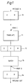
- An incoming message block is shown at 10.
- This message block consists of two parts, namely a message identity part A and an information part B.
- the message identity part is used, together with an incoming connection number C, by a translation circuit 11 to address a local map so as to generate an outgoing message identity shown at D and an outgoing connection number E.
- This message block is shown at 12.
- the outgoing message identity and outgoing connection number are used to switch the message appropriately in a switch indicated at 13.
- the incoming and outgoing connection numbers C and E are respectively the ports at which the message is initially received and subsequently transmitted.
- the final outgoing message shown at 14 thus consists of an outgoing message identity portion part D and the original information part B.
- FIG. 2 of the drawings shows a digital message arriving on a line 20 for switching by a switch 21.
- the message as illustrated in block 10 and as on Figure 1 consists of a message identity portion A and information B.
- a digital switching network such as a telephone exchange messages will be arriving at a large number of ports and as explained the incoming connection or port number, in the present example, C, and the message identity portion A are used to determine the route of the message information across the switch 21.
- This is done by means of a translation circuit 22 which uses the message identity part A and the port number C to address a local map 23.
- the local map 23 is essentially a large memory array which when accessed by the translation circuit 22 maps the incoming message identity A and connection number C to generate the requisite routing information for the message to be transmitted across the switch 21.
- the output of the translation circuit 22 after the mapping function has been carried out is shown at block 10′ and includes the original message identity portion A, the original information B, the port number C, a new, outgoing message identifying portion D, and an outgoing port number E.
- This message block accordingly consists of A, C, which tells where the message has come from, D, E, where the message is going, and B, the message itself.
- This message block is switched across switch 21 to the output port correspondingto outgoing port number E.
- the new message block is supplied to a translation circuit 24.
- This translation circuit 24 acts on the outgoing message identifying portion D and outgoing port number E in a manner similar to translation circuit 22, that is message parts D and E are used to access a local map 25 to generate what is in effect an outgoing message identity portion and outgoing port number.
- the new outgoing message identity and connection portions are merely for use in checking the routing of the switch.
- the translation circuit 24 and local maps 25 are so arranged that they carry out the converse of the operation carried out by translation circuit 22 and local maps 23. Accordingly if the message block has been correctly switched across switch 21 the translation of message identity D and connection number E will give the original message identity A and connection number C.
- the circuit described does not in itself distinguish between the type of faults, other checks may be performed to determine the exact cause of the error. For instance, the maps are likely to relate to a call, and the correct state of the connection according to the call handling be determined and compared with the local maps. If the map at 23 was wrong, then that would fail its check, if the maps at 25 were wrong then that would fail the check, if both where correct, then the most likely fault is the switch 21 itself. There is the possibility that both were wrong, which would suggest that the path has not been correctly set-up in the first place.
Landscapes
- Engineering & Computer Science (AREA)
- Computer Networks & Wireless Communication (AREA)
- Computer Security & Cryptography (AREA)
- Signal Processing (AREA)
- Data Exchanges In Wide-Area Networks (AREA)
- Communication Control (AREA)
- Use Of Switch Circuits For Exchanges And Methods Of Control Of Multiplex Exchanges (AREA)
- Computer And Data Communications (AREA)
- Sub-Exchange Stations And Push- Button Telephones (AREA)
Claims (3)
- Appareil de commutation de messages du type qui comprend une partie de message et une partie d'identité de message reçu, l'appareil comprenant un dispositif générateur (22, 23) qui, à partir de la partie d'identité de message reçu, crée une partie d'identité de message sortant, et un dispositif comprenant un commutateur (21) qui utilise les partie d'identité de message reçu et de message sortant pour l'acheminement du message à une voie de sortie, et caractérisé en ce que l'appareil comporte en outre un dispositif (24, 25) destiné à utiliser la partie d'identité du message sortant pour créer une partie d'identité de message supplémentaire et un dispositif (26, 27) destiné à comparer les parties d'identité du message reçu et du message supplémentaire pour la détection des défauts.
- Appareil selon la revendication 1, caractérisé en outre en ce que le dispositif destiné à utiliser la partie d'identité de message sortant comporte un circuit (24) de transformation et une matrice de tables locales (25).
- Appareil selon la revendication 2, caractérisé en outre en ce qu'il comporte un comparateur (26) destiné à comparer la partie d'identité du message reçu à la partie d'identité du message supplémentaire, et un circuit (27) de détection de défauts destiné à détecter si les deux parties ne sont pas identiques.
Applications Claiming Priority (2)
| Application Number | Priority Date | Filing Date | Title |
|---|---|---|---|
| GB8921082 | 1989-09-18 | ||
| GB898921082A GB8921082D0 (en) | 1989-09-18 | 1989-09-18 | Message routing check system |
Publications (2)
| Publication Number | Publication Date |
|---|---|
| EP0419019A1 EP0419019A1 (fr) | 1991-03-27 |
| EP0419019B1 true EP0419019B1 (fr) | 1994-11-09 |
Family
ID=10663251
Family Applications (1)
| Application Number | Title | Priority Date | Filing Date |
|---|---|---|---|
| EP90308558A Expired - Lifetime EP0419019B1 (fr) | 1989-09-18 | 1990-08-03 | Système de contrôle du routage de messages |
Country Status (13)
| Country | Link |
|---|---|
| US (1) | US5123021A (fr) |
| EP (1) | EP0419019B1 (fr) |
| JP (1) | JP2881185B2 (fr) |
| KR (1) | KR910007308A (fr) |
| CN (1) | CN1050480A (fr) |
| AU (1) | AU6136990A (fr) |
| CA (1) | CA2025500A1 (fr) |
| DE (1) | DE69014047T2 (fr) |
| ES (1) | ES2063922T3 (fr) |
| FI (1) | FI904577A7 (fr) |
| GB (2) | GB8921082D0 (fr) |
| IE (1) | IE902847A1 (fr) |
| PT (1) | PT95325A (fr) |
Families Citing this family (4)
| Publication number | Priority date | Publication date | Assignee | Title |
|---|---|---|---|---|
| JP2892180B2 (ja) * | 1991-04-30 | 1999-05-17 | 富士通株式会社 | Atmクロスコネクト装置の監視方式 |
| GB9311106D0 (en) * | 1993-05-28 | 1993-07-14 | Plessey Telecomm | Switch plane maintenance |
| KR100441159B1 (ko) * | 1999-02-01 | 2004-07-21 | 에스케이씨 주식회사 | 이형 필름 |
| CN105743863A (zh) * | 2014-12-12 | 2016-07-06 | 华为技术有限公司 | 一种对报文进行处理的方法及装置 |
Family Cites Families (8)
| Publication number | Priority date | Publication date | Assignee | Title |
|---|---|---|---|---|
| FR2252718B1 (fr) * | 1973-11-27 | 1978-11-10 | Materiel Telephonique | |
| US3909562A (en) * | 1974-09-12 | 1975-09-30 | Int Standard Electric Corp | Switching network testing process and arrangement |
| US4376999A (en) * | 1980-06-03 | 1983-03-15 | Rockwell International Corporation | Muldem with monitor testing on-line and off-line paths |
| US4486877A (en) * | 1982-06-25 | 1984-12-04 | At&T Bell Laboratories | Packet switching loop-around network and facilities testing |
| US4542507A (en) * | 1983-04-29 | 1985-09-17 | Honeywell Inc. | Apparatus for switch path verification |
| US4561090A (en) * | 1983-05-18 | 1985-12-24 | At&T Bell Laboratories | Integrated self-checking packet switch node |
| EP0163288B1 (fr) * | 1984-05-29 | 1988-11-23 | Siemens Aktiengesellschaft | Méthode pour tester des chemins commutés d'un réseau de connexion multiplex à division dans l'espace |
| DE3801123A1 (de) * | 1988-01-16 | 1989-07-27 | Philips Patentverwaltung | Vermittlungsanlage |
-
1989
- 1989-09-18 GB GB898921082A patent/GB8921082D0/en active Pending
-
1990
- 1990-08-03 DE DE69014047T patent/DE69014047T2/de not_active Expired - Fee Related
- 1990-08-03 EP EP90308558A patent/EP0419019B1/fr not_active Expired - Lifetime
- 1990-08-03 GB GB9017067A patent/GB2236234B/en not_active Expired - Fee Related
- 1990-08-03 ES ES90308558T patent/ES2063922T3/es not_active Expired - Lifetime
- 1990-08-07 IE IE284790A patent/IE902847A1/en unknown
- 1990-08-16 US US07/568,039 patent/US5123021A/en not_active Expired - Fee Related
- 1990-08-23 JP JP22232090A patent/JP2881185B2/ja not_active Expired - Fee Related
- 1990-08-27 AU AU61369/90A patent/AU6136990A/en not_active Abandoned
- 1990-09-14 PT PT95325A patent/PT95325A/pt not_active Application Discontinuation
- 1990-09-17 FI FI904577A patent/FI904577A7/fi not_active IP Right Cessation
- 1990-09-17 KR KR1019900014668A patent/KR910007308A/ko not_active Withdrawn
- 1990-09-17 CA CA002025500A patent/CA2025500A1/fr not_active Abandoned
- 1990-09-18 CN CN90107905A patent/CN1050480A/zh active Pending
Also Published As
| Publication number | Publication date |
|---|---|
| GB8921082D0 (en) | 1989-11-01 |
| JP2881185B2 (ja) | 1999-04-12 |
| GB9017067D0 (en) | 1990-09-19 |
| ES2063922T3 (es) | 1995-01-16 |
| EP0419019A1 (fr) | 1991-03-27 |
| DE69014047T2 (de) | 1995-03-23 |
| DE69014047D1 (de) | 1994-12-15 |
| IE902847A1 (en) | 1991-03-27 |
| US5123021A (en) | 1992-06-16 |
| AU6136990A (en) | 1991-03-21 |
| FI904577A0 (fi) | 1990-09-17 |
| KR910007308A (ko) | 1991-04-30 |
| JPH03117254A (ja) | 1991-05-20 |
| PT95325A (pt) | 1992-05-29 |
| GB2236234B (en) | 1994-03-02 |
| CA2025500A1 (fr) | 1991-03-19 |
| FI904577A7 (fi) | 1991-03-19 |
| GB2236234A (en) | 1991-03-27 |
| CN1050480A (zh) | 1991-04-03 |
Similar Documents
| Publication | Publication Date | Title |
|---|---|---|
| US5329527A (en) | Inter-local area network connecting system | |
| US6647429B1 (en) | Method and apparatus for interconnecting token ring lans operating in ATM | |
| US6658090B1 (en) | Method and system for software updating | |
| US5949755A (en) | ATM emulated path protection | |
| USRE40148E1 (en) | Switched connections diagnostics in a signalling network | |
| EP0597487A2 (fr) | Système de communication à ATM | |
| JPH09116567A5 (fr) | ||
| US6636484B1 (en) | Automatic generation of OAM cells for connection continuity detection | |
| JPH04248729A (ja) | Atm交換機 | |
| US20120224473A1 (en) | Header conversion technique | |
| US5204858A (en) | Address setting and filtering system for terminal accommodating circuits in a packet switching system | |
| US6373845B1 (en) | Multilayer ATM communication equipment | |
| JPH0630025A (ja) | 非同期時分割交換方式 | |
| US5123021A (en) | Message routing check system | |
| US6418120B1 (en) | Congestion avoidance mechanism for ATM switches | |
| JPH11266261A (ja) | 回線交換方法及び、これを用いた非同期モード交換機 | |
| US6389022B1 (en) | Method for controlling the asynchronous transfer mode call in an ATM switching system | |
| US6917619B1 (en) | System and method for interconnecting ATM systems over an intermediate ATM network using switch virtual connections | |
| US5654965A (en) | ATM communication network system with common system information storage | |
| US7164683B1 (en) | Virtual path asynchronous transfer mode switching in a processing satellite communications system | |
| JPH05191434A (ja) | Atmマルチリンク通信方式 | |
| JPH1132052A (ja) | Atm伝送回線切替方式 | |
| KR19980020995A (ko) | 분산처리방식 atm교환기에서의 중계선 루트 데이타베이스 구조 | |
| JPH09181738A (ja) | 優先セルを発生させるための非同期転送モード(atm)で動作するローカルエリアネットワーク | |
| US6990066B1 (en) | Method for using a pre-configured ATM switch and traffic discard to facilitate UPSR selection |
Legal Events
| Date | Code | Title | Description |
|---|---|---|---|
| PUAI | Public reference made under article 153(3) epc to a published international application that has entered the european phase |
Free format text: ORIGINAL CODE: 0009012 |
|
| AK | Designated contracting states |
Kind code of ref document: A1 Designated state(s): BE DE DK ES FR GR IT LU NL SE |
|
| 17P | Request for examination filed |
Effective date: 19910418 |
|
| RAP1 | Party data changed (applicant data changed or rights of an application transferred) |
Owner name: GPT LIMITED |
|
| 17Q | First examination report despatched |
Effective date: 19930709 |
|
| GRAA | (expected) grant |
Free format text: ORIGINAL CODE: 0009210 |
|
| AK | Designated contracting states |
Kind code of ref document: B1 Designated state(s): BE DE DK ES FR GR IT LU NL SE |
|
| PG25 | Lapsed in a contracting state [announced via postgrant information from national office to epo] |
Ref country code: NL Effective date: 19941109 Ref country code: GR Free format text: LAPSE BECAUSE OF FAILURE TO SUBMIT A TRANSLATION OF THE DESCRIPTION OR TO PAY THE FEE WITHIN THE PRESCRIBED TIME-LIMIT Effective date: 19941109 Ref country code: DK Effective date: 19941109 Ref country code: BE Effective date: 19941109 |
|
| ITF | It: translation for a ep patent filed | ||
| ET | Fr: translation filed | ||
| REF | Corresponds to: |
Ref document number: 69014047 Country of ref document: DE Date of ref document: 19941215 |
|
| REG | Reference to a national code |
Ref country code: ES Ref legal event code: FG2A Ref document number: 2063922 Country of ref document: ES Kind code of ref document: T3 |
|
| EAL | Se: european patent in force in sweden |
Ref document number: 90308558.7 |
|
| NLV1 | Nl: lapsed or annulled due to failure to fulfill the requirements of art. 29p and 29m of the patents act | ||
| PGFP | Annual fee paid to national office [announced via postgrant information from national office to epo] |
Ref country code: SE Payment date: 19950816 Year of fee payment: 6 |
|
| PG25 | Lapsed in a contracting state [announced via postgrant information from national office to epo] |
Ref country code: LU Free format text: LAPSE BECAUSE OF NON-PAYMENT OF DUE FEES Effective date: 19950831 |
|
| PLBE | No opposition filed within time limit |
Free format text: ORIGINAL CODE: 0009261 |
|
| STAA | Information on the status of an ep patent application or granted ep patent |
Free format text: STATUS: NO OPPOSITION FILED WITHIN TIME LIMIT |
|
| 26N | No opposition filed | ||
| PG25 | Lapsed in a contracting state [announced via postgrant information from national office to epo] |
Ref country code: SE Effective date: 19960804 |
|
| EUG | Se: european patent has lapsed |
Ref document number: 90308558.7 |
|
| PGFP | Annual fee paid to national office [announced via postgrant information from national office to epo] |
Ref country code: DE Payment date: 20020807 Year of fee payment: 13 |
|
| PGFP | Annual fee paid to national office [announced via postgrant information from national office to epo] |
Ref country code: ES Payment date: 20020826 Year of fee payment: 13 |
|
| PG25 | Lapsed in a contracting state [announced via postgrant information from national office to epo] |
Ref country code: ES Free format text: LAPSE BECAUSE OF NON-PAYMENT OF DUE FEES Effective date: 20030804 |
|
| PGFP | Annual fee paid to national office [announced via postgrant information from national office to epo] |
Ref country code: FR Payment date: 20030804 Year of fee payment: 14 |
|
| PG25 | Lapsed in a contracting state [announced via postgrant information from national office to epo] |
Ref country code: DE Free format text: LAPSE BECAUSE OF NON-PAYMENT OF DUE FEES Effective date: 20040302 |
|
| REG | Reference to a national code |
Ref country code: ES Ref legal event code: FD2A Effective date: 20030804 |
|
| PG25 | Lapsed in a contracting state [announced via postgrant information from national office to epo] |
Ref country code: FR Free format text: LAPSE BECAUSE OF NON-PAYMENT OF DUE FEES Effective date: 20050429 |
|
| REG | Reference to a national code |
Ref country code: FR Ref legal event code: ST |
|
| PG25 | Lapsed in a contracting state [announced via postgrant information from national office to epo] |
Ref country code: IT Free format text: LAPSE BECAUSE OF NON-PAYMENT OF DUE FEES;WARNING: LAPSES OF ITALIAN PATENTS WITH EFFECTIVE DATE BEFORE 2007 MAY HAVE OCCURRED AT ANY TIME BEFORE 2007. THE CORRECT EFFECTIVE DATE MAY BE DIFFERENT FROM THE ONE RECORDED. Effective date: 20050803 |