EP0419054A2 - Schmierstoffabstreifring - Google Patents
Schmierstoffabstreifring Download PDFInfo
- Publication number
- EP0419054A2 EP0419054A2 EP90309249A EP90309249A EP0419054A2 EP 0419054 A2 EP0419054 A2 EP 0419054A2 EP 90309249 A EP90309249 A EP 90309249A EP 90309249 A EP90309249 A EP 90309249A EP 0419054 A2 EP0419054 A2 EP 0419054A2
- Authority
- EP
- European Patent Office
- Prior art keywords
- base
- interface device
- channel
- rim
- connecting means
- Prior art date
- Legal status (The legal status is an assumption and is not a legal conclusion. Google has not performed a legal analysis and makes no representation as to the accuracy of the status listed.)
- Granted
Links
Images

Classifications
-
- F—MECHANICAL ENGINEERING; LIGHTING; HEATING; WEAPONS; BLASTING
- F16—ENGINEERING ELEMENTS AND UNITS; GENERAL MEASURES FOR PRODUCING AND MAINTAINING EFFECTIVE FUNCTIONING OF MACHINES OR INSTALLATIONS; THERMAL INSULATION IN GENERAL
- F16H—GEARING
- F16H57/00—General details of gearing
- F16H57/04—Features relating to lubrication or cooling or heating
- F16H57/0457—Splash lubrication
-
- F—MECHANICAL ENGINEERING; LIGHTING; HEATING; WEAPONS; BLASTING
- F16—ENGINEERING ELEMENTS AND UNITS; GENERAL MEASURES FOR PRODUCING AND MAINTAINING EFFECTIVE FUNCTIONING OF MACHINES OR INSTALLATIONS; THERMAL INSULATION IN GENERAL
- F16H—GEARING
- F16H57/00—General details of gearing
- F16H57/02—Gearboxes; Mounting gearing therein
- F16H57/029—Gearboxes; Mounting gearing therein characterised by means for sealing the gearboxes, e.g. to improve airtightness
-
- F—MECHANICAL ENGINEERING; LIGHTING; HEATING; WEAPONS; BLASTING
- F16—ENGINEERING ELEMENTS AND UNITS; GENERAL MEASURES FOR PRODUCING AND MAINTAINING EFFECTIVE FUNCTIONING OF MACHINES OR INSTALLATIONS; THERMAL INSULATION IN GENERAL
- F16H—GEARING
- F16H57/00—General details of gearing
- F16H57/04—Features relating to lubrication or cooling or heating
- F16H57/048—Type of gearings to be lubricated, cooled or heated
- F16H57/0482—Gearings with gears having orbital motion
-
- F—MECHANICAL ENGINEERING; LIGHTING; HEATING; WEAPONS; BLASTING
- F16—ENGINEERING ELEMENTS AND UNITS; GENERAL MEASURES FOR PRODUCING AND MAINTAINING EFFECTIVE FUNCTIONING OF MACHINES OR INSTALLATIONS; THERMAL INSULATION IN GENERAL
- F16J—PISTONS; CYLINDERS; SEALINGS
- F16J15/00—Sealings
- F16J15/16—Sealings between relatively-moving surfaces
- F16J15/32—Sealings between relatively-moving surfaces with elastic sealings, e.g. O-rings
- F16J15/3204—Sealings between relatively-moving surfaces with elastic sealings, e.g. O-rings with at least one lip
- F16J15/3232—Sealings between relatively-moving surfaces with elastic sealings, e.g. O-rings with at least one lip having two or more lips
-
- F—MECHANICAL ENGINEERING; LIGHTING; HEATING; WEAPONS; BLASTING
- F16—ENGINEERING ELEMENTS AND UNITS; GENERAL MEASURES FOR PRODUCING AND MAINTAINING EFFECTIVE FUNCTIONING OF MACHINES OR INSTALLATIONS; THERMAL INSULATION IN GENERAL
- F16J—PISTONS; CYLINDERS; SEALINGS
- F16J15/00—Sealings
- F16J15/16—Sealings between relatively-moving surfaces
- F16J15/32—Sealings between relatively-moving surfaces with elastic sealings, e.g. O-rings
- F16J15/3268—Mounting of sealing rings
- F16J15/3272—Mounting of sealing rings the rings having a break or opening, e.g. to enable mounting on a shaft otherwise than from a shaft end
-
- F—MECHANICAL ENGINEERING; LIGHTING; HEATING; WEAPONS; BLASTING
- F16—ENGINEERING ELEMENTS AND UNITS; GENERAL MEASURES FOR PRODUCING AND MAINTAINING EFFECTIVE FUNCTIONING OF MACHINES OR INSTALLATIONS; THERMAL INSULATION IN GENERAL
- F16H—GEARING
- F16H57/00—General details of gearing
- F16H57/02—Gearboxes; Mounting gearing therein
- F16H2057/02039—Gearboxes for particular applications
- F16H2057/02043—Gearboxes for particular applications for vehicle transmissions
- F16H2057/0206—Gearboxes for particular applications for vehicle transmissions for commercial vehicles, e.g. buses or trucks
-
- Y—GENERAL TAGGING OF NEW TECHNOLOGICAL DEVELOPMENTS; GENERAL TAGGING OF CROSS-SECTIONAL TECHNOLOGIES SPANNING OVER SEVERAL SECTIONS OF THE IPC; TECHNICAL SUBJECTS COVERED BY FORMER USPC CROSS-REFERENCE ART COLLECTIONS [XRACs] AND DIGESTS
- Y10—TECHNICAL SUBJECTS COVERED BY FORMER USPC
- Y10T—TECHNICAL SUBJECTS COVERED BY FORMER US CLASSIFICATION
- Y10T74/00—Machine element or mechanism
- Y10T74/21—Elements
- Y10T74/2186—Gear casings
-
- Y—GENERAL TAGGING OF NEW TECHNOLOGICAL DEVELOPMENTS; GENERAL TAGGING OF CROSS-SECTIONAL TECHNOLOGIES SPANNING OVER SEVERAL SECTIONS OF THE IPC; TECHNICAL SUBJECTS COVERED BY FORMER USPC CROSS-REFERENCE ART COLLECTIONS [XRACs] AND DIGESTS
- Y10—TECHNICAL SUBJECTS COVERED BY FORMER USPC
- Y10T—TECHNICAL SUBJECTS COVERED BY FORMER US CLASSIFICATION
- Y10T74/00—Machine element or mechanism
- Y10T74/21—Elements
- Y10T74/219—Guards
- Y10T74/2191—Guards for rotary member
Definitions
- a typical gear case 10 comprises a pair of matable sections including an upper or top section 11 and a lower or bottom section 12 which encase moveable parts such as a bull gear 13 (carried by an axle 14) and a pinion gear 16 (Fig. 1) driven by a pinion or armature shaft 17 of a traction motor 23 (Fig. 3).
- the gears 13 and 16 drive axle 14 and wheels 15 (Fig. 3).
- the gear case sections 11 and 12 are kept in alignment with respect to one another along the split-line 18 by metal strips 26 welded along the top gear case sides 20 and 21. Strips 26 overhang the split-line 18 and help provide a groove area into which the split-line edge of the lower section 12 nests.
- Gear case side wall 20 is provided with a semi-circular pinion bore or recess 28 (Figs. 1 & 3) in both the top 11 and bottom 12 which align with one another to provide a circular passage to the inside of the case through which a fixed armature bearing collar or flange 29 may extend.
- the pinion shaft 17 passes through the collar and has the pinion drive gear 16 thereon.
- the top and bottom gear case sidewalls 20 also have two larger semi-circular cutouts/or recesses which align with one another to provide circular passages 31 and 32 through which a rotating surface such as a gear hub 33 and a wheel hub 34 (Fig. 3) may extend.
- Felt or fiber seals 36 may be used to engage the hub surfaces 33 and 34 and a suspension bearing 37.
- Traction motor 23 (shown only in partial section in Fig. 3) drives the armature shaft 17 and pinion gear 16, the latter in turn drives the bull gear 13 secured to the axle 14 and wheels 15.
- the axle rotates in the suspension bearing 37 which is statically retained by the traction motor frame 23.
- the gear case 10 is bolted to the traction motor through the brackets 19 (Fig. 1).
- the traction motor is designed to allow for lateral or axial movement between the axle 14 and the suspension bearings 37.
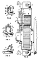
- Fig. 1 An example of the lubricant pressure generated within a gear case is depicted diagrammatically in Fig. 1.
- the bull gear 13 is rotating in the direction R , its teeth scoop or lift lubricant 40 from the bottom of the case and splash it onto the pinion gear 16.
- Meshing of the teeth of the bull gear and pinion gear acts in the nature of a gear pump and causes the lubricant to squirt or spray sideways under high pressure toward the sides of the case and bore 28.
- This pressure shown by the arrow Y (Fig. 3), places high fluid pressure along the bore area 28.
- the pinion bore or cutout 28 is defined by a holding means 42 which may be in the form of a channel (Figs. 3 & 4) formed by an inner side wall 44, an outer side wall 45 and a bottom 46.
- the channel or groove 42 faces or opens radially inwardly toward the cylindrical collar 29.
- gear case 10 may shift during assembly up to approximately 3/8" relative to the pinion collar 9 as depicted by the arrow X (Fig. 3) and 5/16" laterally or axially in the direction of arrow W .
- the relatively thin collar area 29 (in some areas in the nature of 3/8" wide) also accentuates leakage with lateral shifting of a gear case as illustrated in Fig. 4.
- the gear case is made in halves 11 and 12, often times one or both are tilted or tipped during a somewhat blind assembly while nesting between the wheel 15 and motor frame 23 as illustrated in Fig. 6.
- a novel lubricant retaining or interface device 50 (Figs. 4-9).
- the retaining device 50 may be molded from a resilient material such as a pliant, deformable elastomeric material.
- the device 50 includes a base 52, contact means such as a rim 53 having compressible lips 55, means 54 such as a column connecting the rim to the base, and biasing means such as deformable legs 56 extending from the base.
- contact means such as a rim 53 having compressible lips 55
- means 54 such as a column connecting the rim to the base
- biasing means such as deformable legs 56 extending from the base.
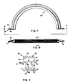
- the device as shown in Fig. 7 may be formed to take on an arcuate or circumferential shape and be used as two generally semi-circular halves to form a circle.
- base 52 extends circumferentially and is preferably sized to be slightly wider than the inside width of the holding channel 42 between the sides 44 and 45 so as to be resiliently held in the channel.
- the column or connecting means 54 extends from the base 52 in a radially inward direction toward the collar 29.
- the column is of a smaller or thinner cross sectional width or thickness (extending in an axial direction parallel to the rotational axis "A" of armature shaft 17) than base 52 and rim 53 and is defined on its sides by circumferential or arcuate grooves or relieved areas 57 (Fig. 9).
- the grooves 57 are formed by the underside wall 58 of rim 53 and a short top wall 59 of base 52, both walls being joined by a connecting side wall 61 of column 54.
- Rim 53 is connected to the column 54 and is located radially inwardly therefrom (toward collar 29). As shown in Figs. 4-6, rim 53 projects wider than column 54 and base 52 and preferably is generally at least as wide as the outside width of channel 42 (across channel sides 44 and 45). In other words, it extends under arcuate edges 60 of the holding channel sidewalls 44 and 45 which define the bore 28 (Figs. 4 & 6). Thus, the rim 53 extends wider than base 52 and preferably at least as wide as the outside width of channel 42 so as to bear against the channel edges 60 which provide support for the rim as will be discussed later.
- the lips 55 Extending from the radially inward side of rim 53 are the lips 55.
- the lips are formed to deformably engage the collar 29.
- a suitable lip shape is shown in Fig. 9 illustrativelying how the circumferentially or arcuately extending lips have a somewhat triangular cross section.
- the lips may have a wider base or bottom 62 extending from rim 53 and may taper radially inwardly to somewhat of a pointed edge or tip 63.
- the biasing means 56 which may include deformable resilient (Fig. 9).
- the inside edges 66 of the legs define a V-notch 67 with the apex 68 thereof extending into the base 52 with the wider open bottom facing radially outwardly toward the holding channel bottom 46.
- the outside tapered edges 70 of the legs together with a short axially extending outer wall 71 of base 52 define arcuately extending pockets 72 with somewhat of a triangular cross section opening toward the respective holding channel side walls 44 and 45.
- the V-notch apex 68 is radially inwardly toward the lips 55 farther than the outer wall 71 of base 52.
- shut off means 75 at the ends such as tabs or flaps (Figs. 7 and 8).
- the tabs project radially away from and at somewhat right angles to the base 52.
- the tabs block off the V-notch 67 in the base ends and' extend laterally away from the base 52 and generally parallel to the gear case split line 18 (Fig. 1). If two devices are mated together, the top surfaces 76 of the respective butting tabs 75 will engage one another. The underside tab surface 77, will then engage the gear case side sheet 20 and 23 of either the top or bottom gear case halves 11 and 12 along their mating split lines 18.
- the device can relieve itself by having the rim 53 bulge back into the side grooves 57 as at 81.
- column 54 can recede further into the channel 42.
- the column 54 can also bulge somewhat laterally into groove 57 and radially outwardly in the direction C into the base 53 as the V-notch 67 allows the base area under column 54 to deform between the resilient legs 56.
- the legs 56 can then bend or deflect into their side pockets 72, and the rim sides 83 can bulge laterally in an axial direction outwardly or beyond the outside of channel walls 44 and 45.
- FIG. 4 Another feature of the invention is illustrated in Fig. 4 wherein it is shown how the retaining device can adjust for misaligned or offset mounting of a gear case due to the excess clearance between the bracket mounting holes 48 and bolts 49.
- This view shows how the center lips indicated at 82 firmly engage the circumferential surface of collar 29 while at the same time another lip 84 straddles and engages side ridges of the collar.
- FIG. 6 A further advantage of the device is illustrated in Fig. 6 wherein it is shown how a gear case half 11 or 12 is often times tipped or jostled during the somewhat blind installation between the wheel 15 and traction motor frame 23. Because the rim underside wall 58 is in effect backed-up and supported by the channel edges 60 and because of the relatively short length of the lips 55, the tendency for the lips to fold under toward the center of the rim 53 is substantially reduced thereby helping to prevent improper lip contact with the collar 29 and also stabilizing the device.
Landscapes
- Engineering & Computer Science (AREA)
- General Engineering & Computer Science (AREA)
- Mechanical Engineering (AREA)
- General Details Of Gearings (AREA)
- Lubrication Of Internal Combustion Engines (AREA)
- Gears, Cams (AREA)
Applications Claiming Priority (2)
| Application Number | Priority Date | Filing Date | Title |
|---|---|---|---|
| US410083 | 1989-09-20 | ||
| US07/410,083 US5123297A (en) | 1989-09-20 | 1989-09-20 | Lubricant retaining device |
Publications (3)
| Publication Number | Publication Date |
|---|---|
| EP0419054A2 true EP0419054A2 (de) | 1991-03-27 |
| EP0419054A3 EP0419054A3 (en) | 1991-12-04 |
| EP0419054B1 EP0419054B1 (de) | 1994-11-30 |
Family
ID=23623132
Family Applications (1)
| Application Number | Title | Priority Date | Filing Date |
|---|---|---|---|
| EP90309249A Expired - Lifetime EP0419054B1 (de) | 1989-09-20 | 1990-08-23 | Schmierstoffabstreifring |
Country Status (12)
| Country | Link |
|---|---|
| US (1) | US5123297A (de) |
| EP (1) | EP0419054B1 (de) |
| JP (1) | JP2881588B2 (de) |
| AR (1) | AR247011A1 (de) |
| AU (1) | AU641681B2 (de) |
| BR (1) | BR9004662A (de) |
| CA (1) | CA2024176C (de) |
| DE (1) | DE69014515T2 (de) |
| ES (1) | ES2025988A6 (de) |
| IE (1) | IE70456B1 (de) |
| MX (1) | MX174289B (de) |
| ZA (1) | ZA906687B (de) |
Cited By (1)
| Publication number | Priority date | Publication date | Assignee | Title |
|---|---|---|---|---|
| US9605760B2 (en) | 2013-08-16 | 2017-03-28 | Electro-Motive Diesel, Inc. | Pinion seal for traction motor gear case |
Families Citing this family (6)
| Publication number | Priority date | Publication date | Assignee | Title |
|---|---|---|---|---|
| US7136753B2 (en) | 2002-12-05 | 2006-11-14 | Denso Corporation | Object recognition apparatus for vehicle, inter-vehicle control apparatus, and distance measurement apparatus |
| JP4525253B2 (ja) * | 2004-08-30 | 2010-08-18 | オムロン株式会社 | 光センサおよび測距方法 |
| US9897210B2 (en) * | 2014-12-08 | 2018-02-20 | United Technologies Corporation | Knife edge seal tree |
| CN105508578B (zh) * | 2015-12-19 | 2018-04-03 | 太原重工股份有限公司 | 开式齿轮总成及其密封装置 |
| CN107676472B (zh) * | 2017-11-14 | 2024-02-27 | 青岛理工大学 | 飞溅润滑自清洁减速器油箱 |
| CN111765240B (zh) * | 2020-07-14 | 2021-06-22 | 安徽聚源昕锐精密机械有限公司 | 一种自动供油的摇臂固定座组及其实施方法 |
Family Cites Families (12)
| Publication number | Priority date | Publication date | Assignee | Title |
|---|---|---|---|---|
| US3225175A (en) * | 1960-07-18 | 1965-12-21 | Scott Paper Co | Case selector |
| GB926789A (en) * | 1962-03-08 | 1963-05-22 | Cadillac Gage Co | Sealing device |
| US3144256A (en) * | 1962-08-06 | 1964-08-11 | Clarence E Wright | Free piston seal |
| US3445121A (en) * | 1967-02-09 | 1969-05-20 | Robert L Lineker | Rear seals for journal boxes |
| US3563557A (en) * | 1968-11-04 | 1971-02-16 | Scovill Manufacturing Co | Dual piston seal |
| US3776559A (en) * | 1970-10-20 | 1973-12-04 | Cooper Roller Bearings | Shaft seals |
| US3710646A (en) * | 1970-11-23 | 1973-01-16 | Bogan D Corp | Gear housing |
| US3727483A (en) * | 1971-09-27 | 1973-04-17 | Nl Industries Inc | Gear casing |
| US3854737A (en) * | 1974-01-21 | 1974-12-17 | Chemprene | Combination rotary and reciprocating unitary sealing mechanism |
| AT332687B (de) * | 1974-12-12 | 1976-10-11 | Vaillant Gmbh | Gliederkessel |
| GB1498181A (en) * | 1975-12-17 | 1978-01-18 | Pioneer Weston Ltd | Rotary shaft seals |
| US4877257A (en) * | 1987-08-19 | 1989-10-31 | Ide Russell D | Piston ring |
-
1989
- 1989-09-20 US US07/410,083 patent/US5123297A/en not_active Expired - Lifetime
-
1990
- 1990-08-22 ZA ZA906687A patent/ZA906687B/xx unknown
- 1990-08-23 EP EP90309249A patent/EP0419054B1/de not_active Expired - Lifetime
- 1990-08-23 DE DE69014515T patent/DE69014515T2/de not_active Expired - Lifetime
- 1990-08-28 CA CA002024176A patent/CA2024176C/en not_active Expired - Lifetime
- 1990-08-30 MX MX022153A patent/MX174289B/es unknown
- 1990-09-12 AR AR90317847A patent/AR247011A1/es active
- 1990-09-12 AU AU62454/90A patent/AU641681B2/en not_active Expired
- 1990-09-19 IE IE338790A patent/IE70456B1/en not_active IP Right Cessation
- 1990-09-19 BR BR909004662A patent/BR9004662A/pt not_active IP Right Cessation
- 1990-09-19 ES ES9002409A patent/ES2025988A6/es not_active Expired - Fee Related
- 1990-09-20 JP JP2249026A patent/JP2881588B2/ja not_active Expired - Fee Related
Cited By (1)
| Publication number | Priority date | Publication date | Assignee | Title |
|---|---|---|---|---|
| US9605760B2 (en) | 2013-08-16 | 2017-03-28 | Electro-Motive Diesel, Inc. | Pinion seal for traction motor gear case |
Also Published As
| Publication number | Publication date |
|---|---|
| JP2881588B2 (ja) | 1999-04-12 |
| EP0419054A3 (en) | 1991-12-04 |
| DE69014515T2 (de) | 1995-06-01 |
| EP0419054B1 (de) | 1994-11-30 |
| IE70456B1 (en) | 1996-11-27 |
| AU641681B2 (en) | 1993-09-30 |
| US5123297A (en) | 1992-06-23 |
| JPH03121399A (ja) | 1991-05-23 |
| CA2024176C (en) | 2001-03-06 |
| ES2025988A6 (es) | 1992-04-01 |
| DE69014515D1 (de) | 1995-01-12 |
| AR247011A1 (es) | 1994-10-31 |
| BR9004662A (pt) | 1991-09-10 |
| CA2024176A1 (en) | 1991-03-21 |
| IE903387A1 (en) | 1991-04-10 |
| AU6245490A (en) | 1991-03-28 |
| MX174289B (es) | 1994-05-03 |
| ZA906687B (en) | 1992-03-25 |
Similar Documents
| Publication | Publication Date | Title |
|---|---|---|
| EP0077617B1 (de) | Schmiermittelabweisungsvorrichtung und damit ausgerüstetes Getriebegehäuse | |
| US6471211B1 (en) | Seal assembly | |
| US6056446A (en) | Clutch release bearing | |
| US6450503B1 (en) | Box-type seal assembly, in particular for vehicle axles | |
| JP5748229B2 (ja) | 満液軸受アイソレータ | |
| US5511886A (en) | Bearing seal with oil deflectors | |
| CA1133727A (en) | Gear case | |
| US20080001362A1 (en) | Split bearing isolator and a method for assembling seal | |
| EP0419054B1 (de) | Schmierstoffabstreifring | |
| RU2771301C1 (ru) | Уплотнительное устройство роликового подшипника и его компонент | |
| EP0811790A1 (de) | Getriebegehäuse | |
| US6056293A (en) | Sealing assembly for a rotary shaft, in particular of an automotive engine water pump | |
| US6976681B2 (en) | Slide ring seal assembly including a radial, rotation preventing arrangement | |
| US3266269A (en) | Sealing element | |
| JPS6018665A (ja) | 流体シ−ル | |
| JPS608568A (ja) | 粘性流体継手 | |
| US6186511B1 (en) | Seal assembly with an interlocking load ring | |
| WO2020055799A1 (en) | Lip seal | |
| EP1049891B1 (de) | Dichtungsanordnung mit stabilisierten dichtungsringen | |
| CN218894948U (zh) | 轮系密封组件和推进轮系 | |
| US20260055792A1 (en) | Affirmatively retained self-sealing bearing cap | |
| AU2019338285A1 (en) | Lip seal | |
| AU2007202857A1 (en) | Split bearing isolator and a method for assembling seal | |
| GB2404229A (en) | A fluid-tight joint between two relatively rotating parts including a flange component with at least one aperture |
Legal Events
| Date | Code | Title | Description |
|---|---|---|---|
| PUAI | Public reference made under article 153(3) epc to a published international application that has entered the european phase |
Free format text: ORIGINAL CODE: 0009012 |
|
| AK | Designated contracting states |
Kind code of ref document: A2 Designated state(s): CH DE FR GB IT LI SE |
|
| PUAL | Search report despatched |
Free format text: ORIGINAL CODE: 0009013 |
|
| AK | Designated contracting states |
Kind code of ref document: A3 Designated state(s): CH DE FR GB IT LI SE |
|
| 17P | Request for examination filed |
Effective date: 19920408 |
|
| 17Q | First examination report despatched |
Effective date: 19930701 |
|
| GRAA | (expected) grant |
Free format text: ORIGINAL CODE: 0009210 |
|
| AK | Designated contracting states |
Kind code of ref document: B1 Designated state(s): CH DE FR GB IT LI SE |
|
| REF | Corresponds to: |
Ref document number: 69014515 Country of ref document: DE Date of ref document: 19950112 |
|
| ITF | It: translation for a ep patent filed | ||
| ET | Fr: translation filed | ||
| PLBE | No opposition filed within time limit |
Free format text: ORIGINAL CODE: 0009261 |
|
| STAA | Information on the status of an ep patent application or granted ep patent |
Free format text: STATUS: NO OPPOSITION FILED WITHIN TIME LIMIT |
|
| 26N | No opposition filed | ||
| REG | Reference to a national code |
Ref country code: GB Ref legal event code: IF02 |
|
| PGFP | Annual fee paid to national office [announced via postgrant information from national office to epo] |
Ref country code: FR Payment date: 20090723 Year of fee payment: 20 |
|
| PGFP | Annual fee paid to national office [announced via postgrant information from national office to epo] |
Ref country code: CH Payment date: 20090722 Year of fee payment: 20 Ref country code: DE Payment date: 20090727 Year of fee payment: 20 Ref country code: GB Payment date: 20090720 Year of fee payment: 20 Ref country code: SE Payment date: 20090722 Year of fee payment: 20 |
|
| PGFP | Annual fee paid to national office [announced via postgrant information from national office to epo] |
Ref country code: IT Payment date: 20090728 Year of fee payment: 20 |
|
| REG | Reference to a national code |
Ref country code: CH Ref legal event code: PL |
|
| REG | Reference to a national code |
Ref country code: GB Ref legal event code: PE20 Expiry date: 20100822 |
|
| EUG | Se: european patent has lapsed | ||
| PG25 | Lapsed in a contracting state [announced via postgrant information from national office to epo] |
Ref country code: GB Free format text: LAPSE BECAUSE OF EXPIRATION OF PROTECTION Effective date: 20100822 |
|
| PG25 | Lapsed in a contracting state [announced via postgrant information from national office to epo] |
Ref country code: DE Free format text: LAPSE BECAUSE OF EXPIRATION OF PROTECTION Effective date: 20100823 |