EP0419194A2 - Schloss mit Dienstschlüsselaussperrvorrichtung und Riegelschutz - Google Patents
Schloss mit Dienstschlüsselaussperrvorrichtung und Riegelschutz Download PDFInfo
- Publication number
- EP0419194A2 EP0419194A2 EP90310170A EP90310170A EP0419194A2 EP 0419194 A2 EP0419194 A2 EP 0419194A2 EP 90310170 A EP90310170 A EP 90310170A EP 90310170 A EP90310170 A EP 90310170A EP 0419194 A2 EP0419194 A2 EP 0419194A2
- Authority
- EP
- European Patent Office
- Prior art keywords
- deadbolt
- lock
- lever
- latch
- retracted
- Prior art date
- Legal status (The legal status is an assumption and is not a legal conclusion. Google has not performed a legal analysis and makes no representation as to the accuracy of the status listed.)
- Withdrawn
Links
Images


Classifications
-
- E—FIXED CONSTRUCTIONS
- E05—LOCKS; KEYS; WINDOW OR DOOR FITTINGS; SAFES
- E05B—LOCKS; ACCESSORIES THEREFOR; HANDCUFFS
- E05B47/00—Operating or controlling locks or other fastening devices by electric or magnetic means
- E05B47/06—Controlling mechanically-operated bolts by electro-magnetically-operated detents
- E05B47/0607—Controlling mechanically-operated bolts by electro-magnetically-operated detents the detent moving pivotally or rotatively
-
- E—FIXED CONSTRUCTIONS
- E05—LOCKS; KEYS; WINDOW OR DOOR FITTINGS; SAFES
- E05B—LOCKS; ACCESSORIES THEREFOR; HANDCUFFS
- E05B35/00—Locks for use with special keys or a plurality of keys ; keys therefor
- E05B35/08—Locks for use with special keys or a plurality of keys ; keys therefor operable by a plurality of keys
- E05B35/10—Locks for use with special keys or a plurality of keys ; keys therefor operable by a plurality of keys with master and pass keys
-
- E—FIXED CONSTRUCTIONS
- E05—LOCKS; KEYS; WINDOW OR DOOR FITTINGS; SAFES
- E05B—LOCKS; ACCESSORIES THEREFOR; HANDCUFFS
- E05B47/00—Operating or controlling locks or other fastening devices by electric or magnetic means
- E05B47/0001—Operating or controlling locks or other fastening devices by electric or magnetic means with electric actuators; Constructional features thereof
- E05B47/0002—Operating or controlling locks or other fastening devices by electric or magnetic means with electric actuators; Constructional features thereof with electromagnets
-
- E—FIXED CONSTRUCTIONS
- E05—LOCKS; KEYS; WINDOW OR DOOR FITTINGS; SAFES
- E05B—LOCKS; ACCESSORIES THEREFOR; HANDCUFFS
- E05B65/00—Locks or fastenings for special use
- E05B65/0032—Locks or fastenings for special use for hotel rooms
-
- Y—GENERAL TAGGING OF NEW TECHNOLOGICAL DEVELOPMENTS; GENERAL TAGGING OF CROSS-SECTIONAL TECHNOLOGIES SPANNING OVER SEVERAL SECTIONS OF THE IPC; TECHNICAL SUBJECTS COVERED BY FORMER USPC CROSS-REFERENCE ART COLLECTIONS [XRACs] AND DIGESTS
- Y10—TECHNICAL SUBJECTS COVERED BY FORMER USPC
- Y10S—TECHNICAL SUBJECTS COVERED BY FORMER USPC CROSS-REFERENCE ART COLLECTIONS [XRACs] AND DIGESTS
- Y10S70/00—Locks
- Y10S70/30—Switch lock
-
- Y—GENERAL TAGGING OF NEW TECHNOLOGICAL DEVELOPMENTS; GENERAL TAGGING OF CROSS-SECTIONAL TECHNOLOGIES SPANNING OVER SEVERAL SECTIONS OF THE IPC; TECHNICAL SUBJECTS COVERED BY FORMER USPC CROSS-REFERENCE ART COLLECTIONS [XRACs] AND DIGESTS
- Y10—TECHNICAL SUBJECTS COVERED BY FORMER USPC
- Y10T—TECHNICAL SUBJECTS COVERED BY FORMER US CLASSIFICATION
- Y10T70/00—Locks
- Y10T70/50—Special application
- Y10T70/5093—For closures
- Y10T70/5155—Door
- Y10T70/5199—Swinging door
- Y10T70/5226—Combined dead bolt and latching bolt
-
- Y—GENERAL TAGGING OF NEW TECHNOLOGICAL DEVELOPMENTS; GENERAL TAGGING OF CROSS-SECTIONAL TECHNOLOGIES SPANNING OVER SEVERAL SECTIONS OF THE IPC; TECHNICAL SUBJECTS COVERED BY FORMER USPC CROSS-REFERENCE ART COLLECTIONS [XRACs] AND DIGESTS
- Y10—TECHNICAL SUBJECTS COVERED BY FORMER USPC
- Y10T—TECHNICAL SUBJECTS COVERED BY FORMER US CLASSIFICATION
- Y10T70/00—Locks
- Y10T70/70—Operating mechanism
- Y10T70/7051—Using a powered device [e.g., motor]
- Y10T70/7057—Permanent magnet
-
- Y—GENERAL TAGGING OF NEW TECHNOLOGICAL DEVELOPMENTS; GENERAL TAGGING OF CROSS-SECTIONAL TECHNOLOGIES SPANNING OVER SEVERAL SECTIONS OF THE IPC; TECHNICAL SUBJECTS COVERED BY FORMER USPC CROSS-REFERENCE ART COLLECTIONS [XRACs] AND DIGESTS
- Y10—TECHNICAL SUBJECTS COVERED BY FORMER USPC
- Y10T—TECHNICAL SUBJECTS COVERED BY FORMER US CLASSIFICATION
- Y10T70/00—Locks
- Y10T70/70—Operating mechanism
- Y10T70/7051—Using a powered device [e.g., motor]
- Y10T70/7062—Electrical type [e.g., solenoid]
-
- Y—GENERAL TAGGING OF NEW TECHNOLOGICAL DEVELOPMENTS; GENERAL TAGGING OF CROSS-SECTIONAL TECHNOLOGIES SPANNING OVER SEVERAL SECTIONS OF THE IPC; TECHNICAL SUBJECTS COVERED BY FORMER USPC CROSS-REFERENCE ART COLLECTIONS [XRACs] AND DIGESTS
- Y10—TECHNICAL SUBJECTS COVERED BY FORMER USPC
- Y10T—TECHNICAL SUBJECTS COVERED BY FORMER US CLASSIFICATION
- Y10T70/00—Locks
- Y10T70/70—Operating mechanism
- Y10T70/7051—Using a powered device [e.g., motor]
- Y10T70/7062—Electrical type [e.g., solenoid]
- Y10T70/713—Dogging manual operator
Definitions
- This invention relates to electrically driven locking systems comprising an exterior operator which is only operable after a proper code input, such as a magnetic strip card or perforated card or manipulation of a keyboard is entered into the lock. More specifically, this invention relates to such a system additionally having means settable from the interior which maintains the exterior operator of the latch as inoperative despite the entry of the proper code input.
- the settable means may be set when a deadbolt is extended. The lockout is cancelled when the latch is retracted and in the deadbolt versions the deadbolt is retracted at the same time.
- the individual guest rooms are often equipped with electric lock systems which area operable from the hall side by a perforated card, a card having a magnetic strip, or a numerical keyboard.
- code input is received by the system and electronically compared with the preset code. If there is a "match", the exterior door operator is then made operable so that the room may be entered. At all times, of course, the lock is operable from the inside of the room so that the occupant can freely leave the room.
- the hotel manager for instance, to get into the room with his code input in the event that the occupant, for instance, has not been heard from for two or three days, in the event of fire, or other special incidents.
- US 4396 914 gives the outline of an electronic security system having key card input. code-receiving means are disclosed in US 4 488 036.
- the present invention is an electrically driven lock which has code-receiving and enabling means adapted to make operable the exterior operator upon receiving suitable code input on the outside of the door.
- the switch actuator preferably includes a pushbutton arrangement on the inside lock housing wherein the side of the pushbutton has an irregular profile which affect the position of a lever, one end of which operates the switch and the other end of which is exposed to the operation of a cancelling pin on the latch retractor.
- the switch is put in a lockout-engaged condition as the lever moves to one position.
- the latch retractor is retracted subsequently, the lever is moved to a second position which changes the switch to lockout-disengaged condition.
- the switch is electrically tied to the circuit board of the reader or other code-receiving circuit within the housing of the lock. Depending on how the switch is connected into the circuit the desired levels of master key will be blocked by the lockout system.
- the electric switch may be moved by a cam fixedly mounted on the operating shaft of a turnpiece for a deadbolt usually positioned above the latchbolt.
- the deadbolt may be biased toward the retracted position and when the bolt is extended, it may be held in that position against the force of a biasing spring by a lever similar to the one described above, the lever having a finger on its one end which fits into a notch in the periphery of the cam.
- the lockout switch is engaged by the can whenever the dead-bolt is extended, and the lockout is cancelled when the pin on the latch retractor moves the other end of the lever as described above.
- a detent holds the spring-biased deadbolt extended and the lever presses the deadbolt to overcome the detent and start the deadbolt on its travel toward retracted position.
- the invention relates to means for protecting the deadbolt and frame of the associated door against the inadvertent or purposeful attempt to close a door with the deadbolt extended for, as described immediately above, the latch, on being retracted, will move the lever causing the deadbolt to rapidly retract, driven by its biasing spring.
- the lip on the latchbolt strike may be slightly extended to assure that there is ample time for the deadbolt to retract before the deadbolt strikes the frame of the door.
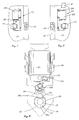
- Figs. 1 and 2 show views of the inside and outside respectively of a lock embodying the invention, the lock being generally designated 10.
- a latch 16 is provided in the end of the door.
- the exterior operator 12 passes through a housing 22 which may include a card reader as disclosed in butts above by which the lock may receive a code on the keycard K inserted into the slot 24.
- the housing 22 may also enclose appropriate circuit boards bearing the logic well described in US 4 396 914.
- a disabling or maid lockout button 28 is provided and projects out an opening in the inside housing 26.
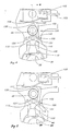
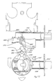
- Fig. 3 shows the base plate 30 as it would appear if the inside operator 14 and the inside housing 26 were removed.
- the plate is apertured as at 32 with an upward extension 34 to permit the passage of the tubular spindle 36 and threaded flange 38 of the interior operator.
- a cancelling pin 40 to be described is mounted on part of the latch retractor and operates freely in the aperture extension 34.
- a bracket 42 is provided with frictionally holds a pack of batteries B for the operation of blocking solenoid and the code-receiving and enabling means all as described in US 4 396 914.
- Suitable conductors may extend through an opening in the door and convey power over to the reader and circuit board within the housing 22.
- One of the wires may extend from the reader through the door to the solenoid 50 mounted inside the tubular spindle 36. These wires are generally not shown in order to avoid unnecessary complications of the drawings.
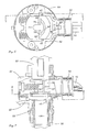
- a portion of the wire 52 to the solenoid is shown in fig. 7.
- FIG. 6 shows in section the housing 54 of a cylindrical lockset. It comprises a latch retractor 56 which is defined by a pair of legs 58 and 58′ are joined by the retractor plate 74 which is formed with a pair of angles 76 and 76′ which are alternately engaged between ends of the spindle pull-back scoops 78 and 80, one for each operator spindle 82 in the case of the exterior spindle and 36 for the interior spindle.
- the retractor will also move leftwardly if the latch is depressed as, for instance, when the latch bolt hits the strike in normal closing.
- retraction of the strike either in automatic closing of the door or movement of one of the operators 12, 14 will cause the cancelling pin 40 to move leftwardly (Fig. 6,7) for purposes which will appear.
- the pin 40′ (Fig. 3) serves as cancelling pin if the hand of the door is reversed so that the latch, for instance, in Fig. 7 would extend to the left instead of the right. In that event pin 40′ would be above the spindle 36.
- the lockout means is best shown in fig. 4. It comprises a microswitch 102′ mounted on the plate 30 just under the battery bracket 42. It has a lead 103 and is provided with a spring operating arm 104 so that when the arm is in the upward position, the switch engages the lockout and when the arm is down, the lockout is disengaged.
- the actuator for changing the position of the switch features the pushbutton 28 and the lever 106.
- Lever 106 comprises a lower portion 108 which is apertured at 110 and received a fulcrum pin 112 (Fig. 8).
- the pin as shown is formed with an enlarged hub 114 which fits snugly in an opening 116 in the plate 30.
- the hub 114 may have a suitable enlarged flange 118 which abutts the plate 30 and is sandwiched between the plate and the door (not shown in fig. 8).
- the pin is reduced to provide a shoulder 119 against which the lever 106 abutts.
- the upper portion 120 of the lever has at its bottom a dovetail fitting 122 which fits into a complementary opening 124 in the lower portion 108. Note that a similar complementary opening 124′ is provided on the opposite side of the lower half 108 to receive the dovetail fitting 122 in the event of change of hand of the door.
- the upper portion 120 has an inward finger 126 which abutts the switch arm 104.
- the pushbutton 28 is mounted on a fixed stem 130 (Fig. 8).
- the stem passes through a suitable opening 132 in the plate 30 and a flange 134 butts up against the plate 30.
- the stem is tubular, its central bore 136 being reduced outwardly of plate 30 to present a shoulder 138 against which the head 140 is screwed into a tapped opening 144 in the inside of the button 28.
- a spring 146 which bottoms on a shoulder 148 in the stem on one side and the floor 150 of the opening 152 on the other side biases the button in the up position.
- the profile of the button includes a peripheral land 154 which normally engages the upper end 120 of the lever 106 and a depressed peripheral land 156 which engages the lever when the button 28 is depressed.
- a spiral spring 160 winds about the hub 114 of the pin 112 and one end 162 is bent to engage in an opening in the upper portion 120 of the lever. The other end abutts against the stem (Fig. 8). This biases the arm so that its upper end engages the selected land 154 or 156.
- the guest pushes the button 28.
- This moves the button against the bias of spring 146 so that the upper portion 120 of the arm 106 snaps down on to the peripheral land 156, driven by spring 160.
- the finger 126 moves the switch 102 to a position in which the lockout is engaged.
- the code- receiving and enabling means does not effect the unblocking of the exterior operator 12 despite the entry of a suitable code, for instance, into the slot 24 (Fig. 2).
- cancelling operation can also be effected as the pin 40 moves leftwardly in the retraction of the latch as it engages the strike mounted on the door frame.
- the automatic closing will cancel the lockout as the latch retracts in latching.
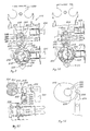
- FIG. 9 through 12 A modified form of the invention is shown in Fig. 9 through 12 wherein the lock is generally designated 210. It comprises a base plate 230 mounted as in the earlier described embodiment on the opposite side of the door from the housing 22 and its accoutrements.
- Base plate 230 mounts a cylindrical lockset 232 having its associated latch 234 with a tubular housing 236 all of which is conventional.
- the cylindrical lockset comprises the U-shaped retractor 238 which engages the tailpiece 240 from the latchbolt in the conventional manner.
- the shoes 242 and 242′ are associated with a retractor so that when the pullback scoop 244 is operated by the inside or outside operator, the latch 234 is retracted.
- the cancelling pin 246 and 246′ which is mounted on the retractor 138 to move therewith.
- the deadbolt 250 Disposed above the latchbolt is the deadbolt 250 which has a tubular housing 252 secured to the base plate 230.
- the deadbolt is operated in the conventional way by a turnpiece 254 which is mounted on the outside of a housing 26 (Fig. 1) and which operates a shaft 256 journaled on the base plate 230.
- the deadbolt 250 is provided with a conventional rack 260 which is engaged by a pinion-like shape 262 on the inward end of the shaft 256.
- the base plate 230 is formed with a pin 270 to the outer end of which is pivoted a two-piece lever 272 and 274 similar to the structure 108 and 120 of the earlier embodiment.
- the shaft 256 has fixedly mounted thereon a cam 276.
- the cam assumes the position of Fig. 9 wherein it engages the actuator arm 278 of the switch 280 mounted on the base plate 230.
- the switch 280 is connected to the logic circuitry of the lock which is disposed inside a housing similar to housing 22 on the opposite side of the door in the same manner as switch 102 in the earlier version.
- a helical spring 282 surrounds the shaft 256 preferably between the cam 276 and the base plate 230.
- the opposite ends of the spring 282 engage respectively an anchor pin 284 and an opening 286 in the cam. This biases the cam in the counterclockwise direction, biasing the deadbolt in the retracted position.
- a second spring 290 surrounds the pin 270 of the lever 272, 274 with one end of the spring extending through an opening 292 in the upper end 274 of the lever and the other end engaging the leftward side of the anchoring pin 284 (Fig. 9). This biases the lever 272, 274 in a counterclockwise direction so that the upper end of the upper portion 274 of the lever rides against the periphery of the cam 276.
- the upper end 274 of the lever is formed with an inward finger 294 (Fig. 12) and the cam is formed with an inward notch 296 in its periphery in a position which works out to be opposite the latch lobe of the cam 276 because the switch arm 278 is on the other side of the cam from the notch (Fig. 9).
- the lockout is effected by turning the turnpiece 254 in a clockwise direction, extending the deadbolt 250 into its keeper in the door frame. This rotation of the turnpiece moves the cam 276 around to the position shown in Fig. 9 engaging the actuator 278 to move the switch 280 into lockout-engaged position.
- the switch 280 is connected to the circuit board in the housing 126 on the other side of the door so that, despite the otherwise suitable matter of the code fed into the lock, the outside operator continues to be disabled.
- the turnpiece 254 may be turned in a counterclockwise direction forcing the rounded finger 294 out of the notch 296 in the periphery of the cam 276. This causes the cam to rotate counterclockwise disengaging the actuator 278 on the switch 280 and reverting the logic circuitry to lock-out-disengaged condition.
- the lock out may be disengaged by simply operating the latch 234 by turning the inside operator. This causes the retractor 238 to move leftwardly along with pin 246 (Fig. 9). Pin 246 engages the lower end of the lower portion 272 of the lever and moves the lever against the urging of the spring 290 in a clockwise direction lifting the finger 294 radially outward from the notch 296 (Fig. 12) and permitting the spring 282 to rotate the shaft 256 in a counterclockwise direction retracting the deadbolt 250.
- the lockout may be cancelled (if the door is ajar) by merely closing the door.
- This causes the latchbolt 234 to retract as it engages its strike.
- This retraction drives leftwardly the retractor 238 and its pin 246.
- Leftward movement of pin 246 causes it to engage the leg 272, 274 of the lever (Fig. 10).
- the upper portion 274 of the lever moves rightwardly (Fig. 10) out of the recess 296 permitting the cam 276 to rotate counterclockwise, driven by the spring 282.
- This powers the deadbolt 250 into retracted position.
- the lobe of the cam 276 moves away from the arm 278, cancelling the lockout feature in the logic circuit in the housing 22 on the other side of the door. Thereafter the maid's keycard and other keycards which were "locked out" will be effective.
- the turnpiece drive shaft 256′ is, however, provided with a plate 306 which is thickened at its outer end to provide a curved cam 308. This cam is adapted to interact with the curved upper end 274a of the upper portion 274′ of the lever 272′, 274′.
- the actuator arm 278′ and the switch 280′ are positioned to be engaged by the cam 308 when the deadbolt 250′ is extended.
- a helical spring 282′ circumposes the turnpiece 256′ and has one end extending through a small opening 286′ in the plate 306. The other end of the spring 282′ engages the anchoring pin 284′ as in the Fig. 9 embodiment. As before, the spring 282′ urges the shaft 256′ in a counterclockwise direction biasing the deadbolt 250′ toward its retracted position.
- the maid lockout may be set by turning the turnpiece (not shown) on the shaft 246′. This drives the deadbolt 250′ outward into its keeper in the frame until its inner end is engaged by the detent 310, the latter holding the deadbolt in the extended position against the force of the spring 282.
- the retractor 238′ moves leftwardly (Fig. 13) and in doing so, contacts the leg 272′ of the lever 272′, 274′.
- the upper end 274a of the lever then moves rightwardly, engaging the underside of the cam 308 to give the turnpiece shaft 256 sufficient force to break the hold of the detent 310 and permit the deadbolt 250 to return leftwardly to its retracted position.
- the arm 278′ is disengaged by the cam 308 so that the lockout is cancelled.
- Figs. 14 through 16 show a still further embodiment of the invention which does not necessarily involve a code-receiving and enabling means. Rather it is directed to the cooperation between the operation of a latchbolt and deadbolt so that the retraction of the latchbolt automatically and immediately causes retraction of the deadbolt.
- This idea is broadly disclosed in the US 4183 563 but that device requires operation of the inside operator to retract the deadbolt.
- the latchbolt 412 is controlled in the conventional manner as described above by the retractor 414 inside the cylindrical lockset 416.
- the retractor includes the lateral deadbolt retraction pin 418 having a structure as described in earlier embodiments.
- a lever having lower portion 420 and upper portion 422 is pivoted as at 424 between the cylindrical lockset 416 and the deadlatch housing 426. It is biased by the helical spring 428 in a counterclockwise direction as described in earlier embodiments, one end of the spring 428 being tucked against the anchoring pin 430 and the other end passing through a smaller opening 432 in the upper end 422 of the lever.
- the upper end 422 is formed with a finger 434 which fits into a notch 435 in the periphery of a disk 436 on the turnpiece shaft 438.
- a second helical spring 440 has one end resting against th anchoring pin 430 and the other end passing through an opening 442 in the disk 436. This biases the shaft 438 of the turnpiece (not shown) in a counterclockwise direction so that the deadbolt 444 is biased in the retracted position.
- a further application of the concept of the Figs. 14, 15 embodiment is that the lip 510 of the strike 512 for the latchbolt 412 may be extended as shown in Fig. 16. With this structure when the latchbolt 412 engages the lip 512 in closing, it will be retracted and if, inadvertently or otherwise, the deadbolt 444 is in its extended position (Fig. 16) it will be retracted through the operation of the parts described in connection with fig. 14.
Landscapes
- Lock And Its Accessories (AREA)
Applications Claiming Priority (2)
| Application Number | Priority Date | Filing Date | Title |
|---|---|---|---|
| US408568 | 1989-09-18 | ||
| US07/408,568 US4979383A (en) | 1989-09-18 | 1989-09-18 | Lock having maid lockout and deadbolt protector |
Publications (2)
| Publication Number | Publication Date |
|---|---|
| EP0419194A2 true EP0419194A2 (de) | 1991-03-27 |
| EP0419194A3 EP0419194A3 (en) | 1992-08-19 |
Family
ID=23616798
Family Applications (1)
| Application Number | Title | Priority Date | Filing Date |
|---|---|---|---|
| EP19900310170 Withdrawn EP0419194A3 (en) | 1989-09-18 | 1990-09-18 | Lock having maid lock-out and deadbolt protector |
Country Status (4)
| Country | Link |
|---|---|
| US (1) | US4979383A (de) |
| EP (1) | EP0419194A3 (de) |
| AU (1) | AU623321B2 (de) |
| CA (1) | CA2018984A1 (de) |
Cited By (1)
| Publication number | Priority date | Publication date | Assignee | Title |
|---|---|---|---|---|
| SG158759A1 (en) * | 2004-01-30 | 2010-02-26 | Assa Abloy Australia Pty Ltd | A three mode lock |
Families Citing this family (24)
| Publication number | Priority date | Publication date | Assignee | Title |
|---|---|---|---|---|
| NO313761B1 (no) * | 1996-06-13 | 2002-11-25 | Vingcard As | Anordning ved lås, spesielt en elektromagnetisk låseenhet |
| US5775142A (en) * | 1996-12-03 | 1998-07-07 | Kim; Jitae | Electronic door lock |
| DE19754923C1 (de) * | 1997-12-10 | 1999-04-01 | Sesam Elektronische Sicherheit | Türbeschlag |
| CA2310971C (en) | 1999-09-22 | 2004-09-21 | Samuel Kennedy | Deadbolt cover |
| US6584818B2 (en) * | 2001-01-19 | 2003-07-01 | Schlage Lock Company | Interconnected lock with lock status sensor |
| US20050183480A1 (en) * | 2002-08-19 | 2005-08-25 | Hingston Neil R. | Electric lock |
| US7207199B2 (en) * | 2003-08-20 | 2007-04-24 | Master Lock Company. Llc | Dead locking deadbolt |
| US7963134B2 (en) * | 2003-08-20 | 2011-06-21 | Master Lock Company Llc | Deadbolt lock |
| NZ548681A (en) * | 2004-01-30 | 2007-12-21 | Assa Abloy Australia Pty Ltd | A three mode lock, including a passage mode, a privacy mode and a deadlock mode. |
| RU2266384C1 (ru) * | 2004-06-01 | 2005-12-20 | Рылеев Михаил Юрьевич | Замок и его защелка (варианты) |
| US7712343B2 (en) * | 2004-09-01 | 2010-05-11 | Master Lock Company Llc | Dead locking deadbolt |
| USD515401S1 (en) * | 2004-09-17 | 2006-02-21 | John D. Brush & Co., Inc. | Biometric interface for a locking mechanism |
| US20070125621A1 (en) * | 2005-12-06 | 2007-06-07 | Locknet, Llc | Token Operated Access Control System |
| US20070163863A1 (en) * | 2006-01-17 | 2007-07-19 | Computerized Security Systems, Inc. | Water resistant keycard reader assembly for an electronic lock |
| USD545662S1 (en) * | 2006-05-30 | 2007-07-03 | Xianhao Lu | Door lock with security key code |
| KR100756673B1 (ko) * | 2006-11-30 | 2007-09-07 | 주식회사 케이코하이텍 | 도어록킹장치 |
| US20090112346A1 (en) * | 2007-10-24 | 2009-04-30 | Steffen Tichatschke | Method and System for Adaptive Equipment Notifications |
| US8925809B2 (en) | 2008-10-20 | 2015-01-06 | Codman Neuro Sciences Sarl | Key-card access system for providing selective access to medical equipment |
| CA141216S (en) * | 2011-01-04 | 2014-01-23 | Guli Security Products Ltd | Electronic three pole lock |
| US8590948B2 (en) * | 2011-01-12 | 2013-11-26 | I-Tek Metal Mfg. Co., Ltd | Outer operational device for panic exit door lock |
| MX345362B (es) | 2011-12-09 | 2017-01-27 | Sargent Mfg Co | Mecanismo de liberación, accionado por incendio, para separar la cerradura electrónica de la puerta contra incendios. |
| US11306508B2 (en) * | 2018-06-23 | 2022-04-19 | Glen LU | Door locking system |
| US11821236B1 (en) | 2021-07-16 | 2023-11-21 | Apad Access, Inc. | Systems, methods, and devices for electronic dynamic lock assembly |
| US20240344357A1 (en) * | 2022-11-02 | 2024-10-17 | Zachary Dan Griffith | Universal door lock indicating devices, kits, and methods |
Family Cites Families (9)
| Publication number | Priority date | Publication date | Assignee | Title |
|---|---|---|---|---|
| US3228717A (en) * | 1963-07-05 | 1966-01-11 | Bull Dog Lock Company | Latch construction |
| US3194596A (en) * | 1963-08-15 | 1965-07-13 | Keeler Brass Co | Door handles |
| US3543546A (en) * | 1968-10-18 | 1970-12-01 | Louis J Gallo | Automobile door safety lock |
| DE1923172A1 (de) * | 1969-05-07 | 1970-11-19 | Eaton Yale & Towne Gmbh | Schliesseinrichtung fuer Riegelfallenschloesser,insbesondere fuer Hotelgastzimmertueren |
| US3967846A (en) * | 1974-04-08 | 1976-07-06 | Schlage Lock Company | Lock |
| US4125008A (en) * | 1975-05-13 | 1978-11-14 | Monitron Industries, Inc. | Electrically operated lock |
| US4183563A (en) * | 1977-11-25 | 1980-01-15 | Scovill Manufacturing Company | Panic-proof lockset |
| US4534194A (en) * | 1981-03-16 | 1985-08-13 | Kadex, Incorporated | Electronic lock system |
| US4967305A (en) * | 1989-01-06 | 1990-10-30 | Datatrak, Inc. | Electronic door lock apparatus, system and method |
-
1989
- 1989-09-18 US US07/408,568 patent/US4979383A/en not_active Expired - Lifetime
-
1990
- 1990-06-14 AU AU57133/90A patent/AU623321B2/en not_active Ceased
- 1990-06-14 CA CA002018984A patent/CA2018984A1/en not_active Abandoned
- 1990-09-18 EP EP19900310170 patent/EP0419194A3/en not_active Withdrawn
Cited By (1)
| Publication number | Priority date | Publication date | Assignee | Title |
|---|---|---|---|---|
| SG158759A1 (en) * | 2004-01-30 | 2010-02-26 | Assa Abloy Australia Pty Ltd | A three mode lock |
Also Published As
| Publication number | Publication date |
|---|---|
| AU5713390A (en) | 1991-03-21 |
| US4979383A (en) | 1990-12-25 |
| CA2018984A1 (en) | 1991-03-18 |
| AU623321B2 (en) | 1992-05-07 |
| EP0419194A3 (en) | 1992-08-19 |
Similar Documents
| Publication | Publication Date | Title |
|---|---|---|
| US4979383A (en) | Lock having maid lockout and deadbolt protector | |
| US5943888A (en) | Keyless entry mechanism | |
| US7069755B2 (en) | Deadbolt lock with electronic touch-key | |
| US4674776A (en) | Mortise lock having secured stops | |
| US4125008A (en) | Electrically operated lock | |
| US5852944A (en) | Remotely controlled door lock | |
| US4561684A (en) | Automatic deadbolt | |
| CA2331512C (en) | Interconnected lock with remote unlocking mechanism | |
| US6612141B2 (en) | Interconnected lock with remote locking mechanism | |
| CA1040233A (en) | Lock knob control mechanism | |
| WO1998006916A1 (en) | Axial moving pushbutton for a lock having rotary locking and release motions | |
| US5845523A (en) | Electronic input and dial entry lock | |
| US7007524B2 (en) | Dead bolt lock system having multiple security features | |
| US20020095958A1 (en) | Interconnected lock with lock status sensor | |
| GB2287981A (en) | Electronic input and dial entry lock | |
| US3954292A (en) | Door latch with turnable lock button | |
| US3866164A (en) | Security system and lock therefor | |
| US3284593A (en) | Alarm lock for doors having a key operated magnetic switch control | |
| EP0168884A2 (de) | Schlösser | |
| US5004278A (en) | Door lock having security device | |
| WO2010046677A1 (en) | Door or window security system for mounting at a door or window frame | |
| GB2039983A (en) | Automatic deadlock | |
| US7424814B2 (en) | Dead bolt lock system having multiple security features | |
| US4759575A (en) | Sliding door lock assembly | |
| US11459795B2 (en) | Electric strike |
Legal Events
| Date | Code | Title | Description |
|---|---|---|---|
| PUAI | Public reference made under article 153(3) epc to a published international application that has entered the european phase |
Free format text: ORIGINAL CODE: 0009012 |
|
| AK | Designated contracting states |
Kind code of ref document: A2 Designated state(s): DE FR GB IT |
|
| PUAL | Search report despatched |
Free format text: ORIGINAL CODE: 0009013 |
|
| AK | Designated contracting states |
Kind code of ref document: A3 Designated state(s): DE FR GB IT |
|
| STAA | Information on the status of an ep patent application or granted ep patent |
Free format text: STATUS: THE APPLICATION IS DEEMED TO BE WITHDRAWN |
|
| 18D | Application deemed to be withdrawn |
Effective date: 19930331 |