EP0419198A2 - Brenner zur Verbrennung von flÀ¼ssigem Brennstoff - Google Patents
Brenner zur Verbrennung von flÀ¼ssigem Brennstoff Download PDFInfo
- Publication number
- EP0419198A2 EP0419198A2 EP90310177A EP90310177A EP0419198A2 EP 0419198 A2 EP0419198 A2 EP 0419198A2 EP 90310177 A EP90310177 A EP 90310177A EP 90310177 A EP90310177 A EP 90310177A EP 0419198 A2 EP0419198 A2 EP 0419198A2
- Authority
- EP
- European Patent Office
- Prior art keywords
- liquid fuel
- burner
- injection holes
- atomization
- promoting fluid
- Prior art date
- Legal status (The legal status is an assumption and is not a legal conclusion. Google has not performed a legal analysis and makes no representation as to the accuracy of the status listed.)
- Granted
Links
Images


Classifications
-
- F—MECHANICAL ENGINEERING; LIGHTING; HEATING; WEAPONS; BLASTING
- F23—COMBUSTION APPARATUS; COMBUSTION PROCESSES
- F23D—BURNERS
- F23D11/00—Burners using a direct spraying action of liquid droplets or vaporised liquid into the combustion space
- F23D11/10—Burners using a direct spraying action of liquid droplets or vaporised liquid into the combustion space the spraying being induced by a gaseous medium, e.g. water vapour
- F23D11/101—Burners using a direct spraying action of liquid droplets or vaporised liquid into the combustion space the spraying being induced by a gaseous medium, e.g. water vapour medium and fuel meeting before the burner outlet
- F23D11/105—Burners using a direct spraying action of liquid droplets or vaporised liquid into the combustion space the spraying being induced by a gaseous medium, e.g. water vapour medium and fuel meeting before the burner outlet at least one of the fluids being submitted to a swirling motion
Definitions
- the present invention relates to a fuel spraying method in a liquid fuel combustion burner used for a heating apparatus as a fleet source of a boiler, a heating furnace and the like, and a liquid fuel combustion burner. More particularly, the present invention relates to a fuel spraying method in a liquid fuel combustion burner having a structure in which a liquid fuel is sprayed together with a fluid flow of air, steam or misty water drop (hereinafter referred to as "atomization-promoting fluid") mixed into the fuel for promoting the atomization of the liquid fuel, and a liquid fuel combustion burner.
- atomization-promoting fluid a fluid flow of air, steam or misty water drop
- a liquid fuel combustion burner having a structure in which a liquid fuel is mixed with an atomization-promoting fluid such as steam or air and the mixed fluid is sprayed from a plurality of injection holes is known.
- the liquid fuel to be mixed with the atomization-promoting fluid is atomized and diffused.
- the present invention has been completed to solve the foregoing problem of the conventional technique, and it is a primary object of the present invention to simultaneously control generation of NO x and generation of soot in a fuel liquid fuel combustion burner having a structure in which a liquid fuel is sprayed together with an atomization-promoting fluid mixed in the liquid fuel and also in a fuel spraying method in this liquid fuel combustion burner.
- a fuel spraying method in a liquid fuel combustion burner which comprises turning a liquid fuel in a flow passage having a sectional area restricted for constringing a flow of the liquid fuel, simultaneously introducing an atomization-promoting fluid into said flow passage to mix the atomization-promoting fluid into the liquid fuel, injecting a plurality of streams of the mixture of the liquid fuel and atomization-promoting fluid from said flow passage, and causing the injected mixture streams to impinge against one another in the presence of combustion air.
- the liquid fuel and the atomization-promoting fluid such as steam are injected into the flow passage and they are mixed in the flow passage.
- the intermediate mixing method is adopted.
- this spraying method is advantageous in that the consumption of steam can be reduced and the atomizing effect can be improved.
- the atomizing effect can be further improved.
- the mixed streams of the liquid fuel and the atomization-promoting fluid be injected so that the crossing angle is in the range of 10 to 120°, preferably 20 to 90°.
- the crossing angle is thus adjusted, the stability of the combustion flame can be further increased.
- a liquid fuel combustion burner attached to the top end portion of a tube projected into the interior of a combustion apparatus proper and having a structure in which a liquid fuel supplied through a fuel passage formed in the interior of the tube is sprayed into the interior of the combustion apparatus proper together with an atomization-promoting fluid supplied through an atomization-promoting fluid passage formed in the interior of the tube and mixed with the fuel, said burner comprising a burner proper having, formed therein, a liquid fuel supply passage, an atomization-promoting fluid supply passage, a plurality of injection holes, a connecting passage connecting the downstream end of the atomization-promoting fluid passage to the injection holes and a connecting passage connecting the downstream end of the liquid fuel supply passage to the side portions of the injection holes, wherein the injection holes are arranged in the state divided into a plurality of groups, each group including a plurality of injection holes, and the respective injection holes are opened in such directions that in each group of the injection holes, the central axes of the injection holes extend to cross one another
- a liquid fuel supplied in the burner proper is introduced in the fuel supply passage, guided to the connecting passage from the fuel supply passage and injected into the injection holes from the side faces of the injection holes.
- the atomization-promoting fluid is introduced into the atomization-promoting fluid supply passage and injected into the interiors of the injection holes from this passage through the connecting passage.
- the liquid fuel flows in the injection hole in the form of a turning stream, is mixed with steam flowing into the injection hole and is sprayed from the top end of the injection hole.
- Streams injected from a plurality of injection holes in each group are caused to impinge against one another in the presence of combustion air in the combustion apparatus.
- the above-mentioned predetermined angle is in the range of from 10 to 120°, preferably from 20 to 90°.
- the respective injection holes be arranged to extend in such directions that in each group of the injection holes, the central axis of the burner proper forms a predetermined angle with the impinging point of the streams from the injection holes, and it is especially preferred that this predetermined angle be 20 to 40°.
- the injection holes are arranged in the vicinity of the peripheral portion of the burner proper and small flames can be formed in the dispersed state, and therefore, a good heat dissipation is attained and the flame temperature can be lowered. Accordingly, the residence time of gas in a high-temperature zone can be shortened.
- a circular recess can be formed as the atomization-promoting fluid supply passage at a central part of the rear end face of the burner proper.
- the productivity of the burner proper can be increased, and mass production and reduction of the cost become possible.
- An annular groove can be formed as the liquid fuel supply passage at a peripheral part of the rear end face of the burner proper.
- the productivity of the burner proper can be increased, and mass production and reduction of the cost become possible.
- the connecting passage connecting the downstream end to the side portions of the respective injection holes can be connected substantially in a tangential direction of each injection hole.
- the productivity of the burner proper can be increased, and mass production and reduction of the cost become possible.
- the burner proper can comprise a fuel supply member and a burner tip connected to the top end portion of the fuel supply member.
- the productivity of the burner proper can be increased, and mass production and reduction of the cost become possible.
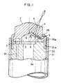
- a liquid fuel combustion burner is inserted through the peripheral wall of a furnace proper as a combustion apparatus proper not shown in the drawings and is used in the state where the top end side of the burner is fixed to the top end portion of a guide pipe 31 projected into the interior of the furnace proper.
- An adapter 32 is inserted and fixed in the guide pipe 31, and in the adapter 32, there are formed passages 33 and 34 connected to a fuel supply pipe and an atomization-promoting fluid supply pipe, which are extended from a fuel supply source and an atomization-promoting fluid supply source, not shown in the drawings.
- a cylindrical cap 35 is engaged with a proper 1 of the burner in the state where the top end face of the burner proper 1 is projected, and by fitting a male screw 35a formed on the peripheral face of the cap 35 to a female screw 31a formed on the inner circumferential face of the guide pipe 31, the burner proper 1 is fixed to the top end portion of the guide pipe 31.
- the passages 33 and 34 communicating with the fuel supply pipe and the atomization-promoting fluid supply pipe are connected to an annular groove 3 and a circular recess 2, described hereinafter, of the burner proper 1.
- the circular recess 2 is formed as the atomization-promoting fluid supply passage at a central part of the rear end face of the burner proper 1.
- This circular recess 2 is formed to have a shape of a circular cone.
- the annular groove 3 is formed at the liquid fuel supply passage at a peripheral part of the rear end face of the burner proper 1.
- an injection hole 4 having one end opened to the inner face of the circular recess 2 through a small-diameter hole 6 and the other end opened to the outer face of the top end portion of the burner proper 1 is formed to pierce between the circular recess 2 and annular groove 3 of the burner proper 1.
- the annular groove 3 and the injection hole 4 are connected to each other through a connecting hole 5 extending from the annular groove 3 substantially in the tangential direction of the injection hole.
- injection holes 4a through 4f are arranged and these injection holes 4a through 4f are divided into three groups, that is, a group of injection holes 4a and 4b, a group of injection holes 4c and 4d and a group of injection holes 4e and 4f. These groups are arranged at three positions spaced by 120° from one another with the central axis of the burner proper 1 being as the center. In each group, the injection holes 4a and 4b, 4c and 4d or 4e and 4f are arranged to extend in such directions that the central axes of the injection holes cross each other at a predetermined angle ⁇ and the central axis of the burner proper 1 forms a predetermined angle ⁇ with the impinging point of the streams injected from the injection holes.
- the predetermined angle ⁇ is 10 to 120°, preferably 20 to 90°, and the predetermined angle ⁇ is 20 to 40°.
- the liquid fuel supplied to the burner proper 1 is introduced into the annular groove 3, guided to the connecting hole 5 from the annular groove 3 and injected from the side face of the injection hole 4 into the interior thereof.
- Steam as the atomization-promoting fluid is introduced into the circular recess 2, guided into the small-diameter hole 6 from the circular recess 2 and injected into the interior of the injection hole 4 from the rear end face of the injection hole 4.
- the liquid fuel flows as a turning stream in the injection hole 4 and is mixed with steam which advances straight from the small-diameter hole 6 and flows into the injection hole 4, and the mixture is jetted from the top end of the injection hole 4.
- each group of the injection holes streams injected from two injection holes are caused to impinge against each other in the presence of combustion air in the combustion apparatus.
- the liquid fuel and the atomization-promoting fluid are injected into the injection hole and they are mixed in the injection hole. That is, the intermediate mixing method is adopted.
- the injection quantity is controlled by changing the pressure of the liquid fuel while maintaining the pressure of the atomization-promoting fluid at a certain level. Therefore, the consumption of the atomization-promoting fluid is advantageously reduced.
- the internal mixing method in which the injection quantity is controlled while maintaining a certain difference between the pressure of the atomization-promoting fluid and the pressure of the liquid fuel is defective in that the consumption of the atomization-promoting fluid is large.
- the atomizing effect is enhanced by a mutual shearing force generated at the impingement, and simultaneously, the contact with oxygen in a boiler or the like where the burner is arranged is promoted and the flame can be dispersed.
- a larger impinging angle of the injected streams is more effective for the atomization, but if the impinging angle is adjusted to 10 to 120°, preferably 20 to 90°, the stability of the combustion flame can be increased.
- the atomizing effect can be further enhanced if the speed of the stream injected from the injection stream 4 is adjusted to an ultrasonic speed.
- the injection holes are arranged 50 that the central axis of the burner proper 1 forms a predetermined angle with the impinging point of the streams injected from two injection holes of each group, dispersed small flames can be formed and a good heat dissipation can be attained, and therefore, the flame temperature can be lowered and the residence time of gas in a high-temperature zone can be shortened.
- the thickness of the flame layer can be reduced and the combustion speed can be increased, and generation of soot can be controlled while controlling generation of NO x can be controlled.
- Table 1 Conventional Burner Burner of Present Invention capacity of boiler 1.5 t/h 1.5 t/h spraying method internal mixing intermediate mixing arrangement of injection holes equidistantly arranged divided in three groups size of injection holes ⁇ 2.6 x 8 holes Fig. 10 ⁇ 2.6 x 6 holes Figs.
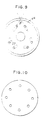
- the conventional burner is one having the injection hole arrangement shown in Fig. 10.
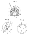
- a burner proper 7 comprises a fuel supply member 8 and a burner tip 9 connected to the fuel supply member 8.
- a circular recess 10 having a top end portion having a shape of a circular cone is formed as the atomization-promoting fluid supply passage at a central part of the fuel supply member 8.
- Three liquid fuel supply holes 11 are vertically formed as the liquid fuel supply passage around the circular recess 10 in the fuel supply member 8. A part of the top end face of the fuel supply member 8 is shaved off, and a vacant space 13 acting as the fuel supply passage is formed between this top end face and the bottom face of the burner tip 9.
- the burner tip 9 has a hole 15 having one end opened to the inner face of the circular recess 10 through a small-diameter hole 14 formed in the fuel supply member 8 and the other end opened to the outer face of the top end.
- the injection hole is constructed by the small-diameter hole 14 and the hole 15.
- the opening of the small-diameter hole 14 communicating with the hole 15 is formed on a convex portion 16 formed on the top end face of the fuel supply member 8.
- the vacant space 13 is connected to each small-diameter hole 14 through a pair of connecting grooves 17 formed on the convex portion 16 to extend from both the side faces of the convex portion 16 to both the sides of the small-diameter hole 14 substantially in the tangential direction.
- six injection holes are arranged and they are divided into three groups, which are located separately from one another by 120° in the circumferential direction with the control axis of the burner proper 7 being as the center.
- each group two injection holes are arranged in parallel in the radial direction of the burner proper 7, and these injection holes are extended in such directions that the central axes of the injection holes cross each other at a predetermined angle ⁇ and the central axis of the burner proper 7 forms a predetermined angle ⁇ with the impinging point of the streams injected from the injection holes.
- the predetermined angle ⁇ is 10 to 120°, preferably 20 to 90°, as in the embodiment shown in Figs. 1 through 3, and the predetermined angle is 20 to 40° as in the embodiment shown in Figs. 1 through 3.
- the liquid fuel supplied in the burner proper 7 is introduced into the liquid supply hole 11 and arrives at the vacant space 13 from the liquid fuel supply hole 11. Then, the liquid fuel is injected from both the sides of the small-diameter hole 14 through a pair of the connecting grooves 17 and arrives at the hole 15.
- the liquid fuel flows as a turning stream through the small-diameter hole 14 and hole 15, advance straight from the small-diameter hole 14 and is mixed with steam flowing into the hole 15, and the mixture is injected from the top end of the hole 15.
- a circular recess 20 is formed as the atomization-promoting fluid supply passage at a central part of the rear end face of a fuel supply member 19.
- the fuel supply member 19 has, formed therein, a small-diameter hole 21 having one end connected to the circular recess 20 and the other end opened to the inclined top end face of the fuel supply member 19, liquid fuel supply holes 22a and 22b as the liquid fuel supply passage located around the circular recess 20, a communicating hole 23 having one end communicating with one liquid fuel supply hole 22a and the other end opened to the top of the fuel supply member 19, and a communicating hole 30 having one end communicating with the other liquid fuel supply hole 22b and the other end opened to an annular groove 28 formed on the rear end face of a burner tip 24.
- a circular recess 25 communicating with the communicating hole 23 opened to the top of the fuel supply member 19 is formed at a central part of the rear face of the burner tip 24, and a vacant space 26 acting as the fuel supply passage is formed between the circular recess 25 and the top end face of the fuel supply member 8.
- a hole 27 having one end opened to the inner face of the circular recess 20 through the small-diameter hole 21 and the other end having a hole 27 opened to the outer face of the top thereof is formed to pierce through the burner tip 24.
- the injection hole is constructed by these small-diameter hole 21 and hole 27.
- a communicating groove 29a connecting the vacant space 26 to the hole 27 and a communicating groove 29b connecting the annular groove 28 to the hole 27 are formed.
- These communicating grooves 29a and 29b extend substantially in the tangential direction of the hole 27 and communicates with the hole 27.
- injection holes are formed and they are divided into three groups.
- the three groups of the injection holes are located separately from one another by 120° in the circumferential direction with the central axis of the burner proper 18 being as the center.
- the two injection holes are formed to extend in such directions that the central axes of the injection holes cross each other at a predetermined angle ⁇ and the center axis of the burner proper 18 forms a predetermined angle ⁇ with the impinging point of the streams injected from the injection holes.
- the predetermined angle ⁇ is 10 to 120°, preferably 20 to 90°, as in the embodiment shown in Figs. 1 through 3 and the embodiment shown in Figs. 4 through 6.
- the predetermined angle ⁇ is 20 to 40°, as in the foregoing embodiments,
- liquid fuel combustion burner having the above-mentioned structure
- a part of the liquid fuel supplied in the burner proper 18 is introduced into the liquid fuel supply hole 22a, arrives at the vacant space 26 through the communicating hole 26 and is then guided to the hole 27 through the communicating groove 29a.
- the remainder of the liquid fuel is introduced into the liquid fuel supply hole 22b, arrives at the annular groove 28 through the communicating hole 30 and is guided to hole 27 through the communicating groove 29b.
- the liquid fuel flows as a turning stream in the hole 27 and is mixed with steam which advances straight from the small-diameter hole 21 and flows into the hole 27, and the mixture is injected from the top end of the hole 27.
- a plurality of injection holes are divided into a plurality of groups, each consisting of two injection holes, but in the present invention, the injection holes can be divided into a plurality of groups, each consisting of 3 or 4 injection holes.
Landscapes
- Engineering & Computer Science (AREA)
- Chemical & Material Sciences (AREA)
- Combustion & Propulsion (AREA)
- Mechanical Engineering (AREA)
- General Engineering & Computer Science (AREA)
- Nozzles For Spraying Of Liquid Fuel (AREA)
Applications Claiming Priority (4)
| Application Number | Priority Date | Filing Date | Title |
|---|---|---|---|
| JP241672/89 | 1989-09-20 | ||
| JP1241672A JP2537411B2 (ja) | 1989-09-20 | 1989-09-20 | 液体燃料燃焼用バ―ナ― |
| JP265173/89 | 1989-10-13 | ||
| JP26517389A JPH0826969B2 (ja) | 1989-10-13 | 1989-10-13 | 液体燃料燃焼用バーナーにおける燃焼方法 |
Publications (3)
| Publication Number | Publication Date |
|---|---|
| EP0419198A2 true EP0419198A2 (de) | 1991-03-27 |
| EP0419198A3 EP0419198A3 (en) | 1992-01-22 |
| EP0419198B1 EP0419198B1 (de) | 1996-04-17 |
Family
ID=26535379
Family Applications (1)
| Application Number | Title | Priority Date | Filing Date |
|---|---|---|---|
| EP90310177A Expired - Lifetime EP0419198B1 (de) | 1989-09-20 | 1990-09-18 | Brenner zur Verbrennung von flüssigem Brennstoff |
Country Status (3)
| Country | Link |
|---|---|
| US (1) | US5176324A (de) |
| EP (1) | EP0419198B1 (de) |
| DE (1) | DE69026563T2 (de) |
Cited By (4)
| Publication number | Priority date | Publication date | Assignee | Title |
|---|---|---|---|---|
| EP0572223A1 (de) * | 1992-05-28 | 1993-12-01 | Nippon Oil Co. Ltd. | Brenner zur Verbrennung von flüssigem Brennstoff |
| WO1995007761A1 (en) * | 1993-09-15 | 1995-03-23 | Electric Power Research Institute | V-jet atomizer |
| EP1944066A2 (de) | 1999-12-22 | 2008-07-16 | Marioff Corporation Oy | Sprühkopf mit durch Bohrungen erzeugten Düsen |
| CN119594405A (zh) * | 2025-01-08 | 2025-03-11 | 宁波方太厨具有限公司 | 外环火盖 |
Families Citing this family (14)
| Publication number | Priority date | Publication date | Assignee | Title |
|---|---|---|---|---|
| DE4238736A1 (de) * | 1992-11-17 | 1994-05-19 | Babcock Feuerungssysteme | Zerstäuber für einen Ölbrenner |
| US5580237A (en) * | 1995-03-09 | 1996-12-03 | Praxair Technology, Inc. | Oxidant lancing nozzle |
| US5680765A (en) * | 1996-01-05 | 1997-10-28 | Choi; Kyung J. | Lean direct wall fuel injection method and devices |
| US5826798A (en) * | 1996-10-01 | 1998-10-27 | Todd Combustion | Atomizer with array of discharge holes to provide improved combustion efficiency and process |
| EP0924459A1 (de) * | 1997-12-17 | 1999-06-23 | Asea Brown Boveri AG | Verfahren und Vorrichtung zum Eindüsen eines Brennstoff-Flüssigkeitsgemisches in die Brennkammer eines Brenners |
| US6024083A (en) * | 1998-12-08 | 2000-02-15 | Eclipse Combustion, Inc. | Radiant tube burner nozzle |
| AU2212400A (en) * | 1998-12-23 | 2000-07-12 | Hanford N. Lockwood | Low pressure dual fluid atomizer |
| US6478239B2 (en) | 2000-01-25 | 2002-11-12 | John Zink Company, Llc | High efficiency fuel oil atomizer |
| DE10207311B4 (de) * | 2002-02-21 | 2005-06-09 | J. Eberspächer GmbH & Co. KG | Zerstäuberdüse für einen Brenner, insbesondere für ein an einem Fahrzeug einsetzbares Heizgerät |
| ITMI20020611A1 (it) * | 2002-03-22 | 2003-09-22 | Danieli Off Mecc | Bruciatore |
| US8070480B2 (en) * | 2003-11-21 | 2011-12-06 | Associated Physics Of America, Llc | Method and device for combusting liquid fuels using hydrogen |
| GB0803959D0 (en) * | 2008-03-03 | 2008-04-09 | Pursuit Dynamics Plc | An improved mist generating apparatus |
| CA2703402C (en) * | 2007-11-09 | 2016-06-14 | Pursuit Dynamics Plc | Misting decontamination system and method |
| US11305142B2 (en) * | 2018-01-12 | 2022-04-19 | Carrier Corporation | End cap agent nozzle |
Family Cites Families (10)
| Publication number | Priority date | Publication date | Assignee | Title |
|---|---|---|---|---|
| US2933259A (en) * | 1958-03-03 | 1960-04-19 | Jean F Raskin | Nozzle head |
| GB1165163A (en) * | 1966-04-30 | 1969-09-24 | Nat Res Dev | Improvements in and relating to Fuel Burning Equipment |
| US3643871A (en) * | 1970-01-30 | 1972-02-22 | Tescom Corp | Torch apparatus |
| FR2288940A1 (fr) * | 1974-10-24 | 1976-05-21 | Pillard Chauffage | Perfectionnements aux bruleurs de combustibles liquides pulverises par la detente d'un fluide auxiliaire et procede d'utilisation de ceux-ci |
| JPS5549162A (en) * | 1978-10-03 | 1980-04-09 | Ikeuchi:Kk | Mist producting device |
| SU787795A1 (ru) * | 1979-02-19 | 1980-12-15 | Запорожский индустриальный институт | Инжекционна горелка |
| US4356970A (en) * | 1979-05-18 | 1982-11-02 | Coen Company, Inc. | Energy saving fuel oil atomizer |
| US4310644A (en) * | 1980-08-14 | 1982-01-12 | Milliken Research Corporation | Vinyl ester resin compositions |
| JPS60126511A (ja) * | 1983-12-09 | 1985-07-06 | Haruji Kurogo | 霧化を促進し燃焼を改善するバ−ナ−・チップ装置 |
| JPS629111A (ja) * | 1985-07-04 | 1987-01-17 | Babcock Hitachi Kk | スラリ−用バ−ナ装置 |
-
1990
- 1990-09-18 EP EP90310177A patent/EP0419198B1/de not_active Expired - Lifetime
- 1990-09-18 DE DE69026563T patent/DE69026563T2/de not_active Expired - Fee Related
- 1990-09-20 US US07/585,786 patent/US5176324A/en not_active Expired - Fee Related
Cited By (6)
| Publication number | Priority date | Publication date | Assignee | Title |
|---|---|---|---|---|
| EP0572223A1 (de) * | 1992-05-28 | 1993-12-01 | Nippon Oil Co. Ltd. | Brenner zur Verbrennung von flüssigem Brennstoff |
| WO1995007761A1 (en) * | 1993-09-15 | 1995-03-23 | Electric Power Research Institute | V-jet atomizer |
| US5685706A (en) * | 1993-09-15 | 1997-11-11 | Electric Power Research Institute | V-jet atomizer |
| EP1944066A2 (de) | 1999-12-22 | 2008-07-16 | Marioff Corporation Oy | Sprühkopf mit durch Bohrungen erzeugten Düsen |
| EP1944066A3 (de) * | 1999-12-22 | 2009-04-15 | Marioff Corporation Oy | Sprühkopf mit durch Bohrungen erzeugten Düsen |
| CN119594405A (zh) * | 2025-01-08 | 2025-03-11 | 宁波方太厨具有限公司 | 外环火盖 |
Also Published As
| Publication number | Publication date |
|---|---|
| DE69026563T2 (de) | 1996-09-12 |
| EP0419198B1 (de) | 1996-04-17 |
| EP0419198A3 (en) | 1992-01-22 |
| DE69026563D1 (de) | 1996-05-23 |
| US5176324A (en) | 1993-01-05 |
Similar Documents
| Publication | Publication Date | Title |
|---|---|---|
| EP0419198B1 (de) | Brenner zur Verbrennung von flüssigem Brennstoff | |
| EP0340424B1 (de) | Sauerstoffstrahlbrenner und Verbrennungsverfahren | |
| US4601428A (en) | Burner tip | |
| US5567141A (en) | Oxy-liquid fuel combustion process and apparatus | |
| CA1294208C (en) | Fuel jet burner and combustion method | |
| EP1443271B1 (de) | Langlocheinspritzdüse und brennervorrichtung mit niedrigen nox emissionen | |
| US6551095B2 (en) | Combustion process and fuel injection burner for implementing such a process | |
| US5147200A (en) | Method of operating a firing installation | |
| US4842509A (en) | Process for fuel combustion with low NOx soot and particulates emission | |
| JP3322887B2 (ja) | 燃料燃焼装置及び方法 | |
| US20030155325A1 (en) | Integrated fluid injection air mixing system | |
| JPH01127067A (ja) | 噴霧ノズル | |
| JPWO1998029690A1 (ja) | 燃料燃焼装置及び方法 | |
| JP2003021309A (ja) | 多流体噴霧ノズルおよび水添加燃焼方法 | |
| EP0419197B1 (de) | Brenner zur Verbrennung von flüssigem Brennstoff | |
| EP0572223A1 (de) | Brenner zur Verbrennung von flüssigem Brennstoff | |
| US5284437A (en) | Method of minimizing the NOx emissions from a combustion | |
| US5681162A (en) | Low pressure atomizer | |
| US20010050318A1 (en) | Integrated fuel injection and mixing system with impingement cooling face | |
| JP3677961B2 (ja) | バーナーにおける燃料霧滴形成方法およびバーナー装置 | |
| KR100231975B1 (ko) | 선화분사 구멍을 가진 질소산화물 저감형 이단노즐 | |
| RU2047049C1 (ru) | Форсунка | |
| JPH03129203A (ja) | 液体燃料燃焼用バーナーにおける燃焼方法 | |
| JPH04371706A (ja) | 液体燃料燃焼用バーナー | |
| CN1072999A (zh) | 产生过程用热的方法与设备 |
Legal Events
| Date | Code | Title | Description |
|---|---|---|---|
| PUAI | Public reference made under article 153(3) epc to a published international application that has entered the european phase |
Free format text: ORIGINAL CODE: 0009012 |
|
| AK | Designated contracting states |
Kind code of ref document: A2 Designated state(s): DE GB IT |
|
| PUAL | Search report despatched |
Free format text: ORIGINAL CODE: 0009013 |
|
| AK | Designated contracting states |
Kind code of ref document: A3 Designated state(s): DE GB IT |
|
| 17P | Request for examination filed |
Effective date: 19920625 |
|
| 17Q | First examination report despatched |
Effective date: 19930804 |
|
| GRAA | (expected) grant |
Free format text: ORIGINAL CODE: 0009210 |
|
| AK | Designated contracting states |
Kind code of ref document: B1 Designated state(s): DE GB IT |
|
| ITF | It: translation for a ep patent filed | ||
| REF | Corresponds to: |
Ref document number: 69026563 Country of ref document: DE Date of ref document: 19960523 |
|
| PGFP | Annual fee paid to national office [announced via postgrant information from national office to epo] |
Ref country code: GB Payment date: 19960917 Year of fee payment: 7 |
|
| PGFP | Annual fee paid to national office [announced via postgrant information from national office to epo] |
Ref country code: DE Payment date: 19961017 Year of fee payment: 7 |
|
| PLBE | No opposition filed within time limit |
Free format text: ORIGINAL CODE: 0009261 |
|
| STAA | Information on the status of an ep patent application or granted ep patent |
Free format text: STATUS: NO OPPOSITION FILED WITHIN TIME LIMIT |
|
| 26N | No opposition filed | ||
| PG25 | Lapsed in a contracting state [announced via postgrant information from national office to epo] |
Ref country code: GB Free format text: LAPSE BECAUSE OF NON-PAYMENT OF DUE FEES Effective date: 19970918 |
|
| GBPC | Gb: european patent ceased through non-payment of renewal fee |
Effective date: 19970918 |
|
| PG25 | Lapsed in a contracting state [announced via postgrant information from national office to epo] |
Ref country code: DE Free format text: LAPSE BECAUSE OF NON-PAYMENT OF DUE FEES Effective date: 19980603 |
|
| PG25 | Lapsed in a contracting state [announced via postgrant information from national office to epo] |
Ref country code: IT Free format text: LAPSE BECAUSE OF NON-PAYMENT OF DUE FEES Effective date: 20050918 |