EP0419280A1 - Appareil de mélange - Google Patents
Appareil de mélange Download PDFInfo
- Publication number
- EP0419280A1 EP0419280A1 EP90310360A EP90310360A EP0419280A1 EP 0419280 A1 EP0419280 A1 EP 0419280A1 EP 90310360 A EP90310360 A EP 90310360A EP 90310360 A EP90310360 A EP 90310360A EP 0419280 A1 EP0419280 A1 EP 0419280A1
- Authority
- EP
- European Patent Office
- Prior art keywords
- flow
- inlet
- tub
- liquid
- mixing
- Prior art date
- Legal status (The legal status is an assumption and is not a legal conclusion. Google has not performed a legal analysis and makes no representation as to the accuracy of the status listed.)
- Granted
Links
- 238000002156 mixing Methods 0.000 title claims abstract description 98
- 239000004568 cement Substances 0.000 claims abstract description 49
- 239000007788 liquid Substances 0.000 claims abstract description 28
- 239000000203 mixture Substances 0.000 claims abstract description 28
- 239000000126 substance Substances 0.000 claims abstract description 26
- 238000000034 method Methods 0.000 claims description 8
- 230000003134 recirculating effect Effects 0.000 claims description 6
- 238000004891 communication Methods 0.000 claims description 5
- XLYOFNOQVPJJNP-UHFFFAOYSA-N water Substances O XLYOFNOQVPJJNP-UHFFFAOYSA-N 0.000 abstract description 64
- 239000002002 slurry Substances 0.000 description 48
- 239000012530 fluid Substances 0.000 description 7
- 230000008569 process Effects 0.000 description 7
- 230000002829 reductive effect Effects 0.000 description 7
- 230000004044 response Effects 0.000 description 7
- 239000000463 material Substances 0.000 description 6
- 230000009471 action Effects 0.000 description 5
- 238000010276 construction Methods 0.000 description 5
- 238000013461 design Methods 0.000 description 4
- 239000000428 dust Substances 0.000 description 4
- 238000005096 rolling process Methods 0.000 description 4
- 230000015572 biosynthetic process Effects 0.000 description 3
- 239000000306 component Substances 0.000 description 3
- 238000005755 formation reaction Methods 0.000 description 3
- 239000008240 homogeneous mixture Substances 0.000 description 3
- 239000002184 metal Substances 0.000 description 3
- 239000011268 mixed slurry Substances 0.000 description 3
- 238000009736 wetting Methods 0.000 description 3
- 230000002411 adverse Effects 0.000 description 2
- 238000013019 agitation Methods 0.000 description 2
- 230000008859 change Effects 0.000 description 2
- 230000008878 coupling Effects 0.000 description 2
- 238000010168 coupling process Methods 0.000 description 2
- 238000005859 coupling reaction Methods 0.000 description 2
- 238000001739 density measurement Methods 0.000 description 2
- 238000010410 dusting Methods 0.000 description 2
- 230000000694 effects Effects 0.000 description 2
- 239000002245 particle Substances 0.000 description 2
- 230000021715 photosynthesis, light harvesting Effects 0.000 description 2
- 238000005086 pumping Methods 0.000 description 2
- 238000005070 sampling Methods 0.000 description 2
- 238000004513 sizing Methods 0.000 description 2
- 238000003466 welding Methods 0.000 description 2
- 238000012935 Averaging Methods 0.000 description 1
- 241000157049 Microtus richardsoni Species 0.000 description 1
- 230000002730 additional effect Effects 0.000 description 1
- 239000000654 additive Substances 0.000 description 1
- 229940000425 combination drug Drugs 0.000 description 1
- 239000000470 constituent Substances 0.000 description 1
- 230000002844 continuous effect Effects 0.000 description 1
- 238000005260 corrosion Methods 0.000 description 1
- 230000007797 corrosion Effects 0.000 description 1
- 230000003628 erosive effect Effects 0.000 description 1
- 239000007789 gas Substances 0.000 description 1
- 230000005484 gravity Effects 0.000 description 1
- 238000000265 homogenisation Methods 0.000 description 1
- 230000006872 improvement Effects 0.000 description 1
- 238000009533 lab test Methods 0.000 description 1
- 238000005259 measurement Methods 0.000 description 1
- 230000000717 retained effect Effects 0.000 description 1
- 230000002441 reversible effect Effects 0.000 description 1
- 238000012163 sequencing technique Methods 0.000 description 1
- 238000011144 upstream manufacturing Methods 0.000 description 1
- 239000011800 void material Substances 0.000 description 1
Images



Classifications
-
- B—PERFORMING OPERATIONS; TRANSPORTING
- B01—PHYSICAL OR CHEMICAL PROCESSES OR APPARATUS IN GENERAL
- B01F—MIXING, e.g. DISSOLVING, EMULSIFYING OR DISPERSING
- B01F23/00—Mixing according to the phases to be mixed, e.g. dispersing or emulsifying
- B01F23/20—Mixing gases with liquids
- B01F23/23—Mixing gases with liquids by introducing gases into liquid media, e.g. for producing aerated liquids
- B01F23/2366—Parts; Accessories
- B01F23/2368—Mixing receptacles, e.g. tanks, vessels or reactors, being completely closed, e.g. hermetically closed
-
- B—PERFORMING OPERATIONS; TRANSPORTING
- B01—PHYSICAL OR CHEMICAL PROCESSES OR APPARATUS IN GENERAL
- B01F—MIXING, e.g. DISSOLVING, EMULSIFYING OR DISPERSING
- B01F25/00—Flow mixers; Mixers for falling materials, e.g. solid particles
- B01F25/10—Mixing by creating a vortex flow, e.g. by tangential introduction of flow components
-
- B—PERFORMING OPERATIONS; TRANSPORTING
- B01—PHYSICAL OR CHEMICAL PROCESSES OR APPARATUS IN GENERAL
- B01F—MIXING, e.g. DISSOLVING, EMULSIFYING OR DISPERSING
- B01F25/00—Flow mixers; Mixers for falling materials, e.g. solid particles
- B01F25/10—Mixing by creating a vortex flow, e.g. by tangential introduction of flow components
- B01F25/103—Mixing by creating a vortex flow, e.g. by tangential introduction of flow components with additional mixing means other than vortex mixers, e.g. the vortex chamber being positioned in another mixing chamber
-
- B—PERFORMING OPERATIONS; TRANSPORTING
- B01—PHYSICAL OR CHEMICAL PROCESSES OR APPARATUS IN GENERAL
- B01F—MIXING, e.g. DISSOLVING, EMULSIFYING OR DISPERSING
- B01F25/00—Flow mixers; Mixers for falling materials, e.g. solid particles
- B01F25/50—Circulation mixers, e.g. wherein at least part of the mixture is discharged from and reintroduced into a receptacle
- B01F25/53—Circulation mixers, e.g. wherein at least part of the mixture is discharged from and reintroduced into a receptacle in which the mixture is discharged from and reintroduced into a receptacle through a recirculation tube, into which an additional component is introduced
-
- B—PERFORMING OPERATIONS; TRANSPORTING
- B01—PHYSICAL OR CHEMICAL PROCESSES OR APPARATUS IN GENERAL
- B01F—MIXING, e.g. DISSOLVING, EMULSIFYING OR DISPERSING
- B01F27/00—Mixers with rotary stirring devices in fixed receptacles; Kneaders
- B01F27/80—Mixers with rotary stirring devices in fixed receptacles; Kneaders with stirrers rotating about a substantially vertical axis
- B01F27/90—Mixers with rotary stirring devices in fixed receptacles; Kneaders with stirrers rotating about a substantially vertical axis with paddles or arms
-
- B—PERFORMING OPERATIONS; TRANSPORTING
- B01—PHYSICAL OR CHEMICAL PROCESSES OR APPARATUS IN GENERAL
- B01F—MIXING, e.g. DISSOLVING, EMULSIFYING OR DISPERSING
- B01F33/00—Other mixers; Mixing plants; Combinations of mixers
- B01F33/80—Mixing plants; Combinations of mixers
- B01F33/82—Combinations of dissimilar mixers
- B01F33/821—Combinations of dissimilar mixers with consecutive receptacles
- B01F33/8212—Combinations of dissimilar mixers with consecutive receptacles with moving and non-moving stirring devices
-
- B—PERFORMING OPERATIONS; TRANSPORTING
- B01—PHYSICAL OR CHEMICAL PROCESSES OR APPARATUS IN GENERAL
- B01F—MIXING, e.g. DISSOLVING, EMULSIFYING OR DISPERSING
- B01F23/00—Mixing according to the phases to be mixed, e.g. dispersing or emulsifying
- B01F23/50—Mixing liquids with solids
- B01F23/56—Mixing liquids with solids by introducing solids in liquids, e.g. dispersing or dissolving
-
- B—PERFORMING OPERATIONS; TRANSPORTING
- B01—PHYSICAL OR CHEMICAL PROCESSES OR APPARATUS IN GENERAL
- B01F—MIXING, e.g. DISSOLVING, EMULSIFYING OR DISPERSING
- B01F27/00—Mixers with rotary stirring devices in fixed receptacles; Kneaders
- B01F27/05—Stirrers
- B01F27/11—Stirrers characterised by the configuration of the stirrers
- B01F27/112—Stirrers characterised by the configuration of the stirrers with arms, paddles, vanes or blades
- B01F27/1125—Stirrers characterised by the configuration of the stirrers with arms, paddles, vanes or blades with vanes or blades extending parallel or oblique to the stirrer axis
-
- B—PERFORMING OPERATIONS; TRANSPORTING
- B01—PHYSICAL OR CHEMICAL PROCESSES OR APPARATUS IN GENERAL
- B01F—MIXING, e.g. DISSOLVING, EMULSIFYING OR DISPERSING
- B01F27/00—Mixers with rotary stirring devices in fixed receptacles; Kneaders
- B01F27/60—Mixers with rotary stirring devices in fixed receptacles; Kneaders with stirrers rotating about a horizontal or inclined axis
- B01F27/61—Mixers with rotary stirring devices in fixed receptacles; Kneaders with stirrers rotating about a horizontal or inclined axis about an inclined axis
-
- B—PERFORMING OPERATIONS; TRANSPORTING
- B01—PHYSICAL OR CHEMICAL PROCESSES OR APPARATUS IN GENERAL
- B01F—MIXING, e.g. DISSOLVING, EMULSIFYING OR DISPERSING
- B01F33/00—Other mixers; Mixing plants; Combinations of mixers
- B01F33/80—Mixing plants; Combinations of mixers
- B01F33/82—Combinations of dissimilar mixers
Definitions
- This invention relates generally to apparatus for mixing at least two substances, especially but not exclusively dry cement and water to form a cement slurry for use in an oil or gas well.
- casing After the bore of an oil or gas well has been drilled, typically a tubular string, referred to as casing, is lowered and secured in the bore to prevent the bore from collapsing and to allow one or more indiividual zones in the geological formation or formations penetrated by the bore to be perforated so that oil or gas from only such zone or zones flows to the mouth of the well.
- casing is typically secured in the well bore by cement which is mixed at the surface, pumped down the open centre of the casing string and back up the annulus which exists between the outer diameter of the casing and the inner diameter of the well bore.
- the mixture of cement to be used at a particular well usually needs to have particular characteristics which make the mixture, referred to as a slurry, suitable for the downhole environment where it is to be used. For example, from one well to another, there can be differences in downhole pressures, temperatures and geological formations which call for different types of cement slurries. Through laboratory tests and actual field experience, a desired type of cement slurry, typically defined at least in part by its desired density, is selected for a particular job.
- the desired type of cement slurry Once the desired type of cement slurry has been selected, it must be accurately produced at the well location. If it is not, adverse consequences can result.
- the slurry density has typically been controlled with the amount of water. Insufficient water in the slurry can result in too high a density and, for example, insufficient volume of slurry being placed in the hole. Also, the completeness of the mixing process can affect the final properties of the slurry. A poorly mixed slurry can produce an inadequate bond between the casing and the well bore. Still another example of the desirability of correctly mixing a selected cement slurry is that additives, such as fluid loss materials and retarders, when used, need to be distributed evenly throughout the slurry to prevent the slurry from prematurely setting up.
- At least one prior system includes a primary water inlet valve which has an adjustable conical space that can become clogged by debris in the water.
- apparatus for producing a mixture from a dry substance and a liquid comprising: flow mixing means for mixing a dry substance and a liquid in a downwardly spiraling flow, said flow mixing means including at least two recirculation inlets; a tub having said flow mixing means disposed therein, said tub having a larger cross-sectional area at its top than at its bottom; an agitator disposed obliquely in said tub so that said agitator, when activated, circulates a mixture received in said tub from said flow mixing means; and recirculation means, connected to said tub and to said at least two recirculation inlets, for recirculating the mixture from said tub into the downwardly spiraling flow within said flow mixing means.
- the flow mixing means further includes a first inlet member, said first inlet member having defined therein an entry port, through which the liquid is received, and an axial opening, said axial opening including an exit port communicating with said entry port; a second inlet member, said second inlet member received in said axial opening of said first inlet member and said second inlet member having an axial passageway defined therethrough through which the dry substance is received; an orifice plate connected to said first inlet member, said orifice plate having defined therein a plurality of orifices disposed below said exit port of said first inlet member; and a valve plate having a plurality of apertures defined therein, said valve plate being disposed between said first inlet member and said orifice plate for movement relative thereto so that said apertures of said valve plate can be selectably registered with said orifices of said orifice plate to control the flow of the liquid communicated through said entry port of said first inlet member for mixing with the dry substance received through said axial passageway of said second inlet member.
- high mixing energy with increased slurry rolling action can be provided within the tub, with increased recirculation rates.
- the present invention can reduce air entrainment.
- the axial flow mixer further comprises an axial body connected to the orifice plate in coaxial relation to the second inlet member, which body has a plurality of grooves defined therein for directing streams of the liquid exiting the orifices with which the apertures register so that tle directed streams form a flow circulating about the axis of the axial body.
- This preferred embodiment further comprises at least two recirculation inlets connected to the axial body, and a diffuser member connected to the axial body so that the circulating flow engages the diffuser member for changing the direction of flow of the circulating flow.
- the present invention also provides a valve, comprising: an orifice plate having a plurality of orifices defined therein; and a valve plate pivotably connected to the orifice plate so that the position to which the valve plate is pivoted determines which of the orifices are open to pass a liquid.
- the valve further comprises jet means, connected to the orifice plate, for directing into a circulating flow liquid passed through open orifices of the orifice plate.
- the orifice plate defines orifice means for providing a selectable area through which a substance can be controllably flowed; and the valve plate defines adjustment means, connected to the orifice means, for permitting the opening of areas, An, through the orifice means, which areas permit flows of the substance at respective volumetric flow rates, Q n , so that the substance flows through the valve at a constant velocity, Q n /A n .
- FIG. 1 Schematically depicted in FIG. 1 is a mixing apparatus 102 of the present invention.
- the apparatus 102 produces a mixture of at least two constituent substances.
- the following description will refer to mixing cement and water to produce a slurry for use in cementing a casing in a well bore, for example; however, the present invention is not limited to such specific substances or application.
- the preferred embodiment of the present invention is particularly adapted for mixing a dry substance and a liquid, the present invention has broader utility (such as liquid and liquid, or liquid and gas).
- FIG. 1 The major components of the apparatus 102 are illustrated in FIG. 1. These include flow mixing means 104 for mixing the dry substance and the liquid in a downwardly spiraling flow; a tub 106 having the flow mixing means 104 disposed therein; an agitator 108 disposed obliquely in the tub 106 so that the agitator 108, when activated, circulates the mixture received in the tub from tle flow mixing means 104; and recirculation means 110, connected to the tub 106 and to the flow mixing means 104, for recirculating the mixture from the tub 106 into the downwardly spiraling flow within the flow mixing means 104.
- a cement slurry 112 is produced within the interior volume of the tub 106.
- FIG. 2 The preferred embodiment of the flow mixing means 104 is shown in FIG. 2, and the preferred embodiment of individual components thereof are more particularly shown in FIGS. 3-11, 16 and 17.
- the flow mixing means 104 is an axial flow mixer which conveys cement axially from the inlet to the outlet of the mixer. That is, there are no elbows or horizontal conduits through which the cement must be conveyed during its mixing with the w.ater prior to being input into the body of slurry 112 in the tub 106.
- Other principle functions of the mixer 104 include:
- the preferred embodiment of the flow mixing means 104 includes an inlet member 114 which in the preferred embodiment is an inlet manifold for the water.
- the inlet member 114 includes an annular top plate 116, an annular bottom plate 118 having a central opening with a larger diameter than the central opening of the plate 116, and a cylindrical side wall 120 connected, such as by welding, to and between the plates 116, 118. These components are disposed relative to each other as shown in FIG. 2 so that an axial opening 122 is defined.
- the bottom of the axial opening 122 provides an exit port 124 through which the water received by the manifold flows in a downward path prior to mixing with cement.
- This water is received through an entry port 126 defined by a horizontal (as disposed in FIG. 2) sleeve 128 connected to the side wall 120 in communication with an opening 130 defined therein.
- the exit port 124 communicates with the entry or inlet port 126 through an annular interior region 132 defined when the inlet member 114 is connected to an inlet member 134 received in the axial opening 122 as shown in FIG. 2.
- the inlet member 114 and the inlet member 134 are connected, such as by welding.
- the inlet member 134 is a sleeve having a cylindrical wall 136 which defines an axial passageway 138 between top and bottom (as oriented in FIG. 2) ends 140, 142 of the sleeve 134.
- the top end 140 is connectable to a conventional bulk cement valve (not shown) so that the sleeve 134 receives cement through the top end 140 and directs it in a downward flow through the bottom end 142.
- the sleeve 134 provides a straight flow path for the cement between the outlet of the bulk cement valve and the outlet of the sleeve 134 where the cement enters a valve 144 of the flow mixing means 104.
- the valve 144 meters the water to be mixed with dry cement coming from the inlet sleeve 134.
- the valve 144 includes an orifice plate 146, a valve plate 148 and means 150 for jetting liquid (specifically water in the example of this description) into admixture with the cement.
- the orifice plate 146 of a specific design contains eighteen orifices or holes, and the valve plate 148 is designed so that it opens six of the eighteen orifices first and then an additional six holes as the valve plate 148 is further rotated and ultimately the final six holes are opened upon further rotation. This allows a maximum hole dimension or passage diameter for a given flow rate as compared to a system which may have the entire passageway opening simultaneously. This controlled opening is important for contaminate passage which could block metering orifices.
- the mixing water as it exits the orifice plate 146, flows in an axial direction and is subsequently turned and directed toward the cement flow path coming from the sleeve 134.
- This turning of the water flow direction is produced by the jet means 150 which in the preferred embodiment has grooves coinciding with the orifice plate 146 orifices.
- the jet means 150 changes the direction of the mixing water from axially downward to slightly tangential and downward. This produces a downwardly spiraling column of fluid circulating about an open center or iris.
- the depths of the grooves of the jet means 150 are staggered so that with high flow rates, back flow up the passage 138 is prevented.
- the orifice plate 146 incluvers an annular member 152 having a central opening 153 defined by an inner periphery 154 about which the plurality of orifices are defined.
- the orifices of the preferred embodiment include three sets of differently sized orifices 156a, 156b, 156c. Each set includes six orifices of the same size. In the illustrated embodiment, the orifices 156a have the smallest diameter, orifices 156b have a larger diameter, and the orifices 156c have the largest diameter of the three sets. These are spaced sequentially and equiangularly around the inner periphery 154 as best seen in FIG. 3.
- the orifices can be the same size or of different sizes and different arrangements.
- a notch or shoulder defined by an annular surface 158 and an adjoining, perpendicularly extending cylindrical surface 160.
- the annular member 152 also has an outer periphery 162 through which holes 164 are defined.
- the holes 164 receive retaining bolts, two of which are shown in FIG. 2 and identified by the reference numeral 166, extending through spacers 186.
- the orifice plate 146 When the orifice plate 146 is connected to the inlet manifold 114 by the retaining bolts 166, the orifices 156 are disposed below the exit port 124 of the inlet manifold 114.
- the orifice plate 146 is also concentrically disposed about the inlet sleeve 134. As shown in FIG. 2, the bottom end 142 of the sleeve 134 abuts the annular surface 158 at the inner periphery 154 of the orifice plate 146. This permits a seal ring 168 to seal against the cylindrical surface 160 of the orifice plate 146 as illustrated in FIG. 2. This also disposes the orifice plate below and adjacent the valve plate 148.
- valve plate 148 The disposition of the valve plate 148 concentrically about the inlet sleeve 134 adjacent the exit port 124 of the inlet manifold 116 is shown in FIG. 2. As disposed, the valve plate 148 is pivotably connected to the orifice plate 146 so that the position to which the valve plate 148 is pivoted determines which of the orifices 156 are open to pass liquid.
- the overall construction of the valve plate 148 is more clearly shown in FlGS. 5 and 6. From these drawings, it is apparent that the preferred embodiment of the valve plate 148 includes a ring 170 from which an actuating arm 172 extends radially outwardly. The arm 172 can be engaged by a suitable actuating device (not shown).
- the ring 170 has an outer periphery from which the arm 172 extends.
- the ring 170 also includes a central opening 173 defined by an inner periphery which has a notched or toothed configuration as most clearly seen in FIG. 5.
- This configuration includes a set of teeth 174a, a set of teeth 174b and a set of teeth 174c.
- Each of the teeth within a respective set has the same width, and the width of each of the teeth 174c is larger than the width of each of the teeth 174b.
- Each of the teeth 174b has a width larger than the width of each of the teeth 174a.
- This sizing corresponds to the different size orifices 156a, 156b, 156c of the orifice plate 146 and the desired sequencing for opening the orifices 156a, 156b, 156c.
- each of the teeth 174a overlies a respective orifice 156a
- each of the teeth 174b overlies a respective orifice 156b
- each of tle teeth 174c overlies a respective orifice 156c.
- This position is obtained by pivoting the valve plate 148 upwardly as shown in FIG. 5 or inwardly into the page of FIG. 2 .
- the respective bolt 166 which lies behind the right hand side bolt 166 shown in FIG.
- these elements of the valve plate 148 define means for simultaneously opening the orifices 156a, 156b, 156c of a respective set in response to pivotation of the valve plate 148.
- the sequence of opening the orifices is such that an overlap exists. For example, the set of orifices 156b starts to open before the set of orifices 156a is fully open. This overlap makes the flow area versus position much smoother, and it can be made to approximate a straight line response if desired.
- the groove 178 is in a surface of the ring 170 facing the orifice plate 146
- the groove 180 is in a surface of the ring 170 facing opposite or away from the orfice plate 146.
- These receive seals (such as O-rings) 182, 184, respectively, as shown in FIG. 2 to seal against the top surface of the orifice plate 146 and the bottom surface of the inlet manifold 114, respectively.
- the seal groove 180 is at a greater diameter than the groove 178, thus the groove 180 encompasses a greater area of the valve plate 148 than is encompassed by the groove 178.
- the pressure which exists during operation acts on the greater upper surface area of the valve plate 148 sealed by the seal 184 to bias the valve plate 148 downward against the orifice plate 146, thereby minimizing leakage between the orifice plate 146 and the valve plate 148.
- valve plate 148 is retained in position by its concentric positioning with the inlet sleeve 134. This main tains the openings 153 (orifice plate 146) and 173 (valve plate 148) aligned; however, it permits the valve plate 148 to be moved relative to the orifice plate 146 so that the apertures 176 of the valve plate 148 can be selectably registered with the orifices 156 of the orifice plate 146 to control the flow of the water received from the exit port 124 of the inlet manifold 114 for mixing with the cement axially received through the axial passageway 138 of the inlet sleeve 134.
- valve plate 148A Shown in FIGS. 16 and 17 is another embodiment of the valve plate, identified therein with the reference numeral 140A.
- the valve plate 148A has the same features as the valve plate 148 as indicated by the use of the same reference numerals; however, the ring 170 of the valve plate 140A includes two separable elements.
- One element is an annular outer support member 278 from which the actuating arm 172 extends.
- the support member 278 is preferably made of a suitable metal, as is the entire embodiment of the previously described valve plate 148.
- the other element is an annular insert 280 disposed within the support member 278 so that the insert 280 seals against the orifice plate 146 in response to pressure when a substance flows through the valve 144.
- the insert 280 is preferably made of a suitable material, such as a suitable plastic, which resists erosion and corrosion from substances flowing through the valve 144 and which exhibits at least some deformation to seal against the surface of the orifice plate 146 when there is flow through the valve 144. This is preferred because metal used at the inner periphery of the ring 170 can erode or corrode and also because metal-to-metal contact between the orifice plate 146 and the valve plate 148 might not create a desired seal.
- a suitable material such as a suitable plastic
- the insert 280 defines the inner periphery of the ring 170 in which the teeth 174 and the apertures 176 are defined.
- the insert 180 itself, has an outer periphery from which protuberances 282 extend. These are releasably received in indentaions 284 defined about the inner periphery of the outer support member 278. These form mortise and tenon joints which hold the insert 280 so that it rotates in response to rotation of the support member 278, but which permit the insert 280 to be separately movable linearly relative to the support member 278 ( e.g ., the insert 280 can be "punched out" of the joints and freed from the support member 278 When the valve 144 is disassembled).
- valve plate 148 (or 148A) are designed in the preferred embodiment to provide a valve through which fluid can be flowed at a constant velocity for different volumetric flow rates.
- constant velocity does not mean absolutely no velocity difference, but rather the term encompasses small velocity differences which are not significant for practical purposes to which the invention is put.
- a design achieving a velocity within five percent of nominal velocity can be considered one which provides "constant velocity," for example.
- K a constant (coefficient of discharge)
- A the flow cross-sectional area (feet 2, 1ft2-.093m2)
- P the pressure differetial.
- the P factor can be considered substantially constant. The pump could be controlled to maintain constant pressure, but in the preferred emboidment of the valve 144 this is not deemed necessary because the effect of the actual pressure change in practice is not deemed significant.
- the orifice plate 146 defines a means for providing a selectable area through which a substance can be controllably flowed
- the valve plate 148 (or 148A) defines an adjustment means, connected to the orifice means, for permitting the opening of areas, A n , through the orifice means, which areas permit flows of the substance at respective volumetric flow rates, Q n , so that the substance flows through the valve 144 at a constant velocity, Q n /A n .
- the liquid jet means 150 is disposed adjacent the bottom end 142 of the inlet sleeve 134 and in communication with the orifice plate 146.
- the liquid jet means 150 directs into a circulating flow water passed through the orifice plate 146 from the downward flow from the inlet manifold 114 so that the downward flow of the cement from the inlet sleeve 134 mixes with the water in the circulating flow.
- the circulating flow is caused by the construction of the jet means 150 which includes an axial body 188 having a plurality of grooves defined therein for directing streams of the water exiting the orifices 156 with which the apertures 176 of the valve plate 148 register so that the directed streams form a flow circulating about an axis 190 of the axial body 188.
- the axis 190 is aligned with the axis of the inlet sleeve 134 so that the axial body 188 is coaxially related to the inlet sleeve 134.
- the axial body 188 of the preferred embodiment is a flanged sleeve wherein the flange is engaged by the collar 192 as shown in FIG. 2.
- the sleeve includes an interior surface 196 in which the plurality of grooves are defined at the flanged end of the jet means sleeve which is secured adjacent the bottom end 142 of the inlet sleeve 134, from which the sleeve or axial body 188 forms an extension.
- the surface 196 defines an axial passageway through the sleeve 188.
- the sleeve is connected to the remainder of the valve 144 so that this axial passageway is aligned with the central openings 153, 173 of the orifice plate 146 and the valve plate 148.
- the grooves defined in the interior surface 196 are of three sizes and orientations to correspond to the orifices 156a, 156b, 156c overlaying and aligned and registering with the grooves.
- the grooves of these three sets are respectively identified by the reference numerals 198a, 198b, 198c. The shape of each of these is more clearly shown in FIGS. 8-10.
- Each of the grooves is formed at an angle to a radius of the cylindrical shape of the axial body 188.
- Each group 198 angles downwardly from a semicircular opening at the top in a manner which is oblique to the axis 190.
- the groove depths are staggered in sequential sets wherein each of three grooves within a set extends to a different depth (e.g. , sequentially deep, deeper, deepest). With high flow rates, this prevents backflow up the passage 138.
- the water received by the grooves is not angled directly down wardly or at the axis 190; rather, the water is directed at an angle as indicated by arrows 200a, 200b, 200c in FIG. 7.
- the result of this angular directing of the flow is to create a downwardly spiraling flow as indicated by the arrow 202 in FIG. 7.
- the valve 144 has a reduced susceptibility to clogging by particles in the mix water, it has a relatively fast opening response time, and it can be tailored to achieve different gains via the different orifice sizes in the orifice plate 146.
- This construction and operation also provides a single source of water control which permits easier manual or automatic control (i.e., only the valve plate 148 needs to be operated for water control). It also communicates more water energy from the same size pumps which have been used with prior systems.
- the downwardly spiraling flow created within the jet means 150, wherein an open iris is formed helps separate entrained air from the water/cement mixture and helps break up the cement.
- the flow mixer 104 also comprises at least two recirculation inlets 206, 208 substantially diametrically opposed and skewed towards the same direction as the water jetting grooves 198 of the jet means 150. That is, as illustrated in FIG. 2 the inlets 206, 208 are sleeves which are disposed in a downward direction and at a slightly tangential angle to create a circular flow pattern. Thus, when a recirculation fluid flows through the recirculation inlets 206, 208, the recirculation fluid enters the circulating flow below the jet means 150 in the same direction of circulation.
- the recirculation inlets 206, 208 are connected to the axial body 188 of the jet means 150 by a containment body or housing 210 as shown in FIG. 2. The containment body 210 extends below the jet means 150.
- a typical maximum recirculation rate in a prior system is 8-10 barrels per minute using a particular type of pump, whereas up to approximately 25 barrels (4000 dm3) per minute can be recirculated in a particular implementation of the present invention using the same type of pump.
- This increased volume and flow rate provides greater mixing energy within the axial flow mixer which improves wetting and breaking up of the dry material. It also permits the contents of the tub 106 to be rolled more quickly to mix the older slurry with the new mixture to make a more homogeneous product. It also enables the recirculation of thicker slurries which have been known to plug the single recirculation inlet of prior systems. Also, faster recirculation provides faster density measurement response (by means of sampling the tub contents faster).
- the flow mixing means 104 further comprises diffuser means 212 for diffusing the circulating, downwardly spiraling flow below the containment body 210 at the bottom of the mixer 104.
- the circulating flow is diffused by engaging the diffuser means whereupon the flow changes its direction of flow.
- the diffuser means 212 is a member which includes a washer-shaped or annular plate 214 to which a plurality of baffle plates 216 are connected.
- Each of the baffle plates 216 includes a concave surface 218 for receiving the circulating flow and changing its direction of flow.
- the baffle plates 216 are connected to the annular plate 214 at equally spaced intervals as best seen in FIG. 11.
- the diffuser means 212 can include a top plate to prevent or reduce vertical splashing.
- the diffuser means 212 is connected to the axial body 188 of the jet means 150 by the containment body 210 and adjustment means for adjusting the distance the diffuser means 212 is disposed below the containment body 210.
- the adjustment means includes a plurality of rods 220. The lower ends of the rods 220 are attached to the diffuser means 212; their upper ends are slideably received in thumbscrew brackets 222 attached to the lower end of the containment body 210.
- the adjustment means permits the diffuser means 212 to be adjusted to the surface of the body of slurry 112 when the flow mixing means 104 is disposed on the tub 106 as illustrated in FIG. 1.
- the outside diameter of the diffuser means 212 is larger than the diameter of the containment body 210.
- the diffuser means 212 has ahole 223 in the center which is approximately the same size as the cement delivery valve.
- the baffles, or vanes, 216 are mounted in a direction such that the direction of rotation of the slurry as it exits the mixer's lower housing defined by the containment body 210 is reversed, thereby aiding in energy dissipation.
- the diffuser means 212 dissipates energy at the surface of the body of slurry 112 when the tub 106 is up to its full operating capacity. This dissipation of energy helps reduce air entrainment. In a particular implementation, air entrainment was reduced by approximately 50% to 90% relative to the air entrainment found produced in a prior system. Having the slurry impact the diffuser means 212 also helps mixing by breaking lumps of dry material that previously have been wetted. It also causes additional mixing due to turbulence. Mixing is further enhanced by the drawing (educating) of slurry from below the diffuser through the hole 223 and mixing it with new slurry in the vane sections of the diffuser.
- the flow mixing means 104 In the operation of the flow mixing means 104, as cement is gravity fed through the inlet sleeve 134, it first encounters the high velocity mixing water jets created within the jet means 150.
- the flow of the mixing water is controlled by operation of the single valve plate 148. Even at low water rates, most of the passageway through the axial body 188 of the jet means 150 is covered by the mixing water. Thus, it is difficult for cement to pass the initial mixing water section without being wetted by water.
- the mixture of cement and water exiting the end of the axial body 188 of the jet means 150 is intersected by the jets of recirculated slurry flowing from the recirculation inlets 206, 208. Through this two-stage high velocity mixing, the slurry circulating down the containment housing 210 is thoroughly mixed and homogeneous.
- the diffuser means 212 is positioned below the containment body 210 approximately five inches (12.7cm), with the diffuser means 212 submerged approximately two inches (5.1cm) into the body of slurry 112 as depicted in FIG. 1.
- the slurry exits the containment housing 210 it has a downward and slightly spiral pattern. This fluid impacts the diffuser means 212 and the tub fluid and is deflected outwardly into the vanes or baffles 216.
- the baffles 216 reverse the flow direction from clockwise to counterclockwise (for the illustrated embodiment), thereby aiding in energy dissipation.
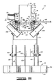
- the tub 106 of the preferred embodiment in which the mixer 104 is mounted has a shape as illustrated in FIGS. 12-15.
- This shape includes a cross-sectional area at its top or mouth which is larger than the cross-sectional area at the bottom of the tub 106. Having a larger area at the top helps expel entrained air, and a smaller area at the bottom enables a faster response time in turning over the slurry and making it into a homogeneous mixture.
- the larger area at the top of the tub 106 is maintained throughout a sufficient height of the tub 106 to accomodate receiving the lower portions of the mixer 104 which is shown in FIG. 12 installed on two mounting brackets 224, 226. Throughout this height, the tub 106 is defined by two curved ends 228, 230 connected by two straight side sections 232, 234 (in FIG. 13).
- the tub 106 can be used in a number of different ways known in the art. As illustrated in FIGs. 14 and 15, one way is to mount the tub on an underlying skid 242 by which the tub 106 can be mounted on a wheeled trailer (not shown).
- a mounting bracket 244 secures the agitator 108 to the tub 106 in the oblique relationship illustrated in the drawings. That is, the bracket 244 retains the agitator 108 so that its axis of rotation 246 is neither parallel nor perpendicular to an axis 248 of the tub 106.
- a hydraulic drive motor 250 to which a driven shaft 252 is connected through a flexible drive coupling 254.
- a paddle 256 Connected to the shaft 252 is a paddle 256.
- the shaft 252 is journaled opposite the coupling 254 in a bearing 258 connected by a bracket 260 to a side wall of the tapered portion 236 of the tub 106.
- the paddle 256 of a particular embodiment has a twenty-two inch diameter versus a more conventional twelve-inch diameter paddle used in one or more prior systems.
- the larger diameter paddle of the present invention in combination with the torque which can be generated by the motor 250 enable more viscous slurries to be agitated using the present invention.
- the agitation which typically occurs includes a flow pattern as illustrated in FIG. 1 by the arrows drawn within the body of slurry 112. This arises from the action of the paddle 256 in combination with a baffle 262 and the incoming mixture received from the mixer 104.
- the circulation illustrated in FIG. 1 shows that the present invention imparts a high rolling action to thoroughly mix the body of slurry 112 into a homogeneous mixture.
- the recirculation means 110 of the mixing apparatus 102 has a preferred embodiment illustrated in FIG. 12.
- This includes a pump 264 having a suction side connected to an outlet 266 of the tub 106 and a pressure side connected to a conduit 268 in which a densimeter 270 is disposed.
- the conduit 268 has a Y-connection 272 to provide two lines for connecting to the two recirculation inlets 206, 208.
- Other configurations, such as having the Y-connector between the pump 264 and the densimeter 270, can be used.
- a pump 274 for pumping mix water through a conduit 276 into the inlet port 126 of the inlet manifold 114 of the mixer 104.
- the operation of the overall mixing apparatus 2 of the preferred embodiment includes circulating the body of slurry 112 in the manner described and illustrated in FIG. 1 and recirculating that body through the recirculation means 110 for remixing in the mixer 104 whose operation has already been described.
- New mixing water is added via the pump 274 and conduit 276, and new cement is added through a cement inlet valve (not shown) in a manner known in the art.
- the cement inlet valve is coupled to the top end 140 of the inlet sleeve 134.
- cementing job quality can be improved and thicker slurries can be mixed at higher rates with the mixing apparatus 102.
- Thick slurries can be mixed at higher rates by using the high-energy initial mixer 104, by increasing the rolling action in the tub 106 by using the larger and higher horsepower agitator 108 and by increasing the recirculation rate through the recirculation means 110.
Landscapes
- Chemical & Material Sciences (AREA)
- Chemical Kinetics & Catalysis (AREA)
- Dispersion Chemistry (AREA)
- Accessories For Mixers (AREA)
- Processing Of Solid Wastes (AREA)
- Confectionery (AREA)
- Mixers Of The Rotary Stirring Type (AREA)
- Preparation Of Clay, And Manufacture Of Mixtures Containing Clay Or Cement (AREA)
Applications Claiming Priority (2)
| Application Number | Priority Date | Filing Date | Title |
|---|---|---|---|
| US07/412,231 US5114239A (en) | 1989-09-21 | 1989-09-21 | Mixing apparatus and method |
| US412231 | 1989-09-21 |
Publications (2)
| Publication Number | Publication Date |
|---|---|
| EP0419280A1 true EP0419280A1 (fr) | 1991-03-27 |
| EP0419280B1 EP0419280B1 (fr) | 1994-11-09 |
Family
ID=23632151
Family Applications (1)
| Application Number | Title | Priority Date | Filing Date |
|---|---|---|---|
| EP90310360A Expired - Lifetime EP0419280B1 (fr) | 1989-09-21 | 1990-09-21 | Appareil de mélange |
Country Status (6)
| Country | Link |
|---|---|
| US (1) | US5114239A (fr) |
| EP (1) | EP0419280B1 (fr) |
| AT (1) | ATE113862T1 (fr) |
| CA (1) | CA2025792A1 (fr) |
| DE (1) | DE69014052T2 (fr) |
| DK (1) | DK0419280T3 (fr) |
Cited By (5)
| Publication number | Priority date | Publication date | Assignee | Title |
|---|---|---|---|---|
| EP0570335A1 (fr) * | 1992-04-30 | 1993-11-18 | Urs Liechti | Dispositif et procédé pour mélanger un composant pulvérulent solide dans un matériau liquide |
| EP0783365A4 (fr) * | 1994-09-30 | 1998-08-12 | Semi Bulk Systems Inc | Module de melange portable |
| WO2000056432A1 (fr) * | 1999-03-19 | 2000-09-28 | Termoelettronica S.P.A. | Dispositif permettant de mettre des matieres en suspension dans un liquide et systeme permettant de preparer des melanges liquide-matieres destines a la teinture au moyen de ce dispositif |
| US9010989B2 (en) | 2008-04-14 | 2015-04-21 | Schlumberger Technology Corporation | Container system |
| JPWO2019087559A1 (ja) * | 2017-10-30 | 2020-12-03 | 日本スピンドル製造株式会社 | スラリー製造装置、およびスラリー製造装置の運転方法 |
Families Citing this family (103)
| Publication number | Priority date | Publication date | Assignee | Title |
|---|---|---|---|---|
| US5503473A (en) * | 1989-08-02 | 1996-04-02 | Stewart & Stevenson Services, Inc. | Automatic cementing system for precisely obtaining a desired cement density |
| US5624182A (en) * | 1989-08-02 | 1997-04-29 | Stewart & Stevenson Services, Inc. | Automatic cementing system with improved density control |
| US5265247A (en) * | 1990-08-15 | 1993-11-23 | Halliburton Company | Laboratory data storage and retrieval system and method |
| US5190374A (en) * | 1991-04-29 | 1993-03-02 | Halliburton Company | Method and apparatus for continuously mixing well treatment fluids |
| DE4217373C2 (de) * | 1992-05-26 | 2003-02-20 | Klaus Obermann Gmbh | Vorrichtung zur Aufbereitung und Bereitstellung von wenigstens einen flüssigen Bestandteil enthaltenden Mischungen oder Suspensionen |
| US5289877A (en) * | 1992-11-10 | 1994-03-01 | Halliburton Company | Cement mixing and pumping system and method for oil/gas well |
| US5382411A (en) * | 1993-01-05 | 1995-01-17 | Halliburton Company | Apparatus and method for continuously mixing fluids |
| US5365435A (en) * | 1993-02-19 | 1994-11-15 | Halliburton Company | System and method for quantitative determination of mixing efficiency at oil or gas well |
| US5522459A (en) * | 1993-06-03 | 1996-06-04 | Halliburton Company | Continuous multi-component slurrying process at oil or gas well |
| US5538341A (en) * | 1995-05-12 | 1996-07-23 | Halliburton Company | Apparatus for mixing |
| US5571281A (en) * | 1996-02-09 | 1996-11-05 | Allen; Thomas E. | Automatic cement mixing and density simulator and control system and equipment for oil well cementing |
| US5701924A (en) * | 1996-10-30 | 1997-12-30 | Caterpillar Inc. | Apparatus and method for detecting and handling liquid separation in liquid emulsions |
| US6592246B2 (en) * | 2000-08-28 | 2003-07-15 | Csir | Method and installation for forming and maintaining a slurry |
| AU2003219848A1 (en) | 2002-02-22 | 2003-09-09 | Flotek Indutries, Inc. | Mobile blending apparatus |
| US20030161211A1 (en) * | 2002-02-28 | 2003-08-28 | Duell Alan B. | Control system and method for forming slurries |
| WO2004003672A1 (fr) * | 2002-06-27 | 2004-01-08 | Hydromix Inc. | Systeme de melange de laitier de ciment |
| CN1332741C (zh) * | 2002-07-19 | 2007-08-22 | 动力系统有限公司 | 混合过程原料的方法和设备 |
| US6932169B2 (en) | 2002-07-23 | 2005-08-23 | Halliburton Energy Services, Inc. | System and method for developing and recycling drilling fluids |
| US7344299B2 (en) * | 2003-10-21 | 2008-03-18 | Mp Equipment Company | Mixing system and process |
| US20080112259A1 (en) * | 2003-10-21 | 2008-05-15 | Mp Equipment Company | Mixing system and process |
| US7284898B2 (en) * | 2004-03-10 | 2007-10-23 | Halliburton Energy Services, Inc. | System and method for mixing water and non-aqueous materials using measured water concentration to control addition of ingredients |
| US20050241545A1 (en) * | 2004-04-28 | 2005-11-03 | Vargo Richard F Jr | Methods of extending the shelf life of and revitalizing lightweight beads for use in cement compositions |
| US20050241538A1 (en) * | 2004-04-28 | 2005-11-03 | Vargo Richard F Jr | Methods of making cement compositions using liquid additives containing lightweight beads |
| US7488141B2 (en) * | 2004-07-14 | 2009-02-10 | Halliburton Energy Services, Inc. | Automated control methods for dry bulk material transfer |
| US7178974B1 (en) * | 2004-08-06 | 2007-02-20 | Bell Marcus O | Plural component polymer grout plant |
| US20060093536A1 (en) * | 2004-11-02 | 2006-05-04 | Selby Daniel R | System and method for mixing a slurry |
| US20060112701A1 (en) * | 2004-11-30 | 2006-06-01 | Halliburton Energy Services, Inc. | Methods and systems for controlling rate and output of heat exchanger fluids |
| US7373981B2 (en) * | 2005-02-14 | 2008-05-20 | Halliburton Energy Services, Inc. | Methods of cementing with lightweight cement compositions |
| US7390356B2 (en) * | 2005-03-11 | 2008-06-24 | Halliburton Energy Services, Inc. | Compositions for high temperature lightweight cementing |
| US7398827B2 (en) * | 2005-03-11 | 2008-07-15 | Halliburton Energy Services, Inc. | Methods for high temperature lightweight cementing |
| DE102005017075A1 (de) * | 2005-04-13 | 2006-10-19 | Ekato Unimix Gmbh | Vorrichtung zum Homogenisieren und/oder Dispergieren fliessfähiger Stoffe |
| US7494263B2 (en) * | 2005-04-14 | 2009-02-24 | Halliburton Energy Services, Inc. | Control system design for a mixing system with multiple inputs |
| US7353874B2 (en) * | 2005-04-14 | 2008-04-08 | Halliburton Energy Services, Inc. | Method for servicing a well bore using a mixing control system |
| EP1745840A1 (fr) * | 2005-07-22 | 2007-01-24 | Services Petroliers Schlumberger | Appareil et procédé de mélange d'un matériau liquide et d'un matériau fluide pulvérulent pour obtenir une suspension |
| US20110235460A1 (en) * | 2005-07-22 | 2011-09-29 | Schlumberger Technology Corporation | Method and apparatus to optimize the mixing process |
| US7567856B2 (en) * | 2005-12-30 | 2009-07-28 | Halliburton Energy Services, Inc. | Methods for determining a volumetric ratio of a material to the total materials in a mixing vessel |
| US7561943B2 (en) * | 2005-12-30 | 2009-07-14 | Halliburton Energy Services, Inc. | Methods for volumetrically controlling a mixing apparatus |
| US20070171765A1 (en) * | 2005-12-30 | 2007-07-26 | Dykstra Jason D | Systems for volumetrically controlling a mixing apparatus |
| US20070153624A1 (en) * | 2005-12-30 | 2007-07-05 | Dykstra Jason D | Systems for determining a volumetric ratio of a material to the total materials in a mixing vessel |
| US7464757B2 (en) * | 2006-06-16 | 2008-12-16 | Schlumberger Technology Corporation | Method for continuously batch mixing a cement slurry |
| US7614276B2 (en) * | 2006-09-06 | 2009-11-10 | Allen Thomas E | Method for determining absolute density of cement slurry |
| US7620481B2 (en) * | 2007-01-10 | 2009-11-17 | Halliburton Energy Services, Inc. | Systems for self-balancing control of mixing and pumping |
| US8177411B2 (en) * | 2009-01-08 | 2012-05-15 | Halliburton Energy Services Inc. | Mixer system controlled based on density inferred from sensed mixing tub weight |
| US9789629B2 (en) | 2010-06-23 | 2017-10-17 | Verifi Llc | Method for adjusting concrete rheology based upon nominal dose-response profile |
| US8311678B2 (en) * | 2010-06-23 | 2012-11-13 | Verifi Llc | Method for adjusting concrete rheology based upon nominal dose-response profile |
| US8899823B2 (en) | 2011-12-09 | 2014-12-02 | Advanced Stimulation Technology, Inc. | Gel hydration unit |
| US10407990B2 (en) | 2012-11-16 | 2019-09-10 | U.S. Well Services, LLC | Slide out pump stand for hydraulic fracturing equipment |
| US11959371B2 (en) | 2012-11-16 | 2024-04-16 | Us Well Services, Llc | Suction and discharge lines for a dual hydraulic fracturing unit |
| US10036238B2 (en) | 2012-11-16 | 2018-07-31 | U.S. Well Services, LLC | Cable management of electric powered hydraulic fracturing pump unit |
| US10232332B2 (en) | 2012-11-16 | 2019-03-19 | U.S. Well Services, Inc. | Independent control of auger and hopper assembly in electric blender system |
| US9995218B2 (en) | 2012-11-16 | 2018-06-12 | U.S. Well Services, LLC | Turbine chilling for oil field power generation |
| US9745840B2 (en) | 2012-11-16 | 2017-08-29 | Us Well Services Llc | Electric powered pump down |
| US9893500B2 (en) | 2012-11-16 | 2018-02-13 | U.S. Well Services, LLC | Switchgear load sharing for oil field equipment |
| US10254732B2 (en) | 2012-11-16 | 2019-04-09 | U.S. Well Services, Inc. | Monitoring and control of proppant storage from a datavan |
| US11449018B2 (en) | 2012-11-16 | 2022-09-20 | U.S. Well Services, LLC | System and method for parallel power and blackout protection for electric powered hydraulic fracturing |
| US11476781B2 (en) | 2012-11-16 | 2022-10-18 | U.S. Well Services, LLC | Wireline power supply during electric powered fracturing operations |
| US10020711B2 (en) | 2012-11-16 | 2018-07-10 | U.S. Well Services, LLC | System for fueling electric powered hydraulic fracturing equipment with multiple fuel sources |
| US9410410B2 (en) | 2012-11-16 | 2016-08-09 | Us Well Services Llc | System for pumping hydraulic fracturing fluid using electric pumps |
| US9970278B2 (en) | 2012-11-16 | 2018-05-15 | U.S. Well Services, LLC | System for centralized monitoring and control of electric powered hydraulic fracturing fleet |
| US9452394B2 (en) | 2013-06-06 | 2016-09-27 | Baker Hughes Incorporated | Viscous fluid dilution system and method thereof |
| US9447313B2 (en) * | 2013-06-06 | 2016-09-20 | Baker Hughes Incorporated | Hydration system for hydrating an additive and method |
| WO2015094323A1 (fr) * | 2013-12-20 | 2015-06-25 | Halliburton Energy Services, Inc. | Procédé et appareil permettant d'améliorer le mélange de coulis de ciment |
| CN107208385B (zh) * | 2014-08-19 | 2020-02-07 | 阿特拉斯·詹姆斯·拉塞尔 | 用于再利用沥青油毡瓦以及生产沥青混合物的系统、方法和设备 |
| CA2908276C (fr) | 2014-10-14 | 2022-11-01 | Us Well Services Llc | Alimentation parallele et protection contre une panne totale pour la fracturation hydraulique electrique |
| US12078110B2 (en) | 2015-11-20 | 2024-09-03 | Us Well Services, Llc | System for gas compression on electric hydraulic fracturing fleets |
| US12027831B2 (en) | 2016-04-15 | 2024-07-02 | U.S. Well Services, LLC | Switchgear load sharing for oil field equipment |
| US11181107B2 (en) | 2016-12-02 | 2021-11-23 | U.S. Well Services, LLC | Constant voltage power distribution system for use with an electric hydraulic fracturing system |
| EP3551410A4 (fr) * | 2016-12-12 | 2020-08-19 | Services Petroliers Schlumberger | Mélange automatisé de ciment |
| US11371314B2 (en) | 2017-03-10 | 2022-06-28 | Schlumberger Technology Corporation | Cement mixer and multiple purpose pumper (CMMP) for land rig |
| US10280724B2 (en) | 2017-07-07 | 2019-05-07 | U.S. Well Services, Inc. | Hydraulic fracturing equipment with non-hydraulic power |
| US11067481B2 (en) | 2017-10-05 | 2021-07-20 | U.S. Well Services, LLC | Instrumented fracturing slurry flow system and method |
| CA3078879A1 (fr) | 2017-10-13 | 2019-04-18 | U.S. Well Services, LLC | Systeme et procede de fracturation automatique |
| WO2019084283A1 (fr) | 2017-10-25 | 2019-05-02 | U.S. Well Services, LLC | Système et procédé de fracturation intelligente |
| CN107899495B (zh) * | 2017-10-30 | 2024-03-22 | 中冶南方都市环保工程技术股份有限公司 | 场地修复药剂配制系统及其使用方法 |
| US10648311B2 (en) | 2017-12-05 | 2020-05-12 | U.S. Well Services, LLC | High horsepower pumping configuration for an electric hydraulic fracturing system |
| WO2019113147A1 (fr) | 2017-12-05 | 2019-06-13 | U.S. Well Services, Inc. | Pompes à pistons multiples et systèmes d'entraînement associés |
| WO2019140331A1 (fr) * | 2018-01-12 | 2019-07-18 | Mgb Oilfield Solutions, Llc | Additif sec et système, ensemble et procédé de mélange de fluide |
| US11114857B2 (en) | 2018-02-05 | 2021-09-07 | U.S. Well Services, LLC | Microgrid electrical load management |
| US11035207B2 (en) | 2018-04-16 | 2021-06-15 | U.S. Well Services, LLC | Hybrid hydraulic fracturing fleet |
| WO2019241783A1 (fr) | 2018-06-15 | 2019-12-19 | U.S. Well Services, Inc. | Unité d'alimentation mobile intégrée pour fracturation hydraulique |
| US11032964B2 (en) | 2018-06-27 | 2021-06-15 | Cnh Industrial Canada, Ltd. | Flow splitting control valve for secondary header |
| WO2020056258A1 (fr) | 2018-09-14 | 2020-03-19 | U.S. Well Services, LLC | Support de colonne montante pour sites de puits |
| WO2020072845A1 (fr) * | 2018-10-05 | 2020-04-09 | University Of Baltimore | Systèmes, procédés et appareil pour utiliser un réservoir de remise en suspension |
| CA3115669A1 (fr) | 2018-10-09 | 2020-04-16 | U.S. Well Services, LLC | Systeme de commutation modulaire et distribution d'energie pour equipement electrique de champ petrolifere |
| WO2020081313A1 (fr) | 2018-10-09 | 2020-04-23 | U.S. Well Services, LLC | Système de pompe de fracturation hydraulique électrique comprenant des remorques de fracturation pour pompe à pistons multiples à alimentation électrique unique, unités de filtration, et plate-forme coulissante |
| US11420167B2 (en) | 2018-10-19 | 2022-08-23 | Phillip J. Bonner | Mobile chemical mixing plant |
| US11578577B2 (en) | 2019-03-20 | 2023-02-14 | U.S. Well Services, LLC | Oversized switchgear trailer for electric hydraulic fracturing |
| US11728709B2 (en) | 2019-05-13 | 2023-08-15 | U.S. Well Services, LLC | Encoderless vector control for VFD in hydraulic fracturing applications |
| CN110156098B (zh) * | 2019-06-03 | 2024-06-18 | 中山市雅乐思净水科技有限公司 | 一种净水机的自清洗系统及其自清洗方法 |
| AR119134A1 (es) | 2019-06-10 | 2021-11-24 | U S Well Services Llc | Calentador integrado de gas de combustión para equipos móviles de acondicionamiento de combustible |
| WO2021022048A1 (fr) | 2019-08-01 | 2021-02-04 | U.S. Well Services, LLC | Système de stockage d'énergie à haute capacité pour fracturation hydraulique électrique |
| US11459863B2 (en) | 2019-10-03 | 2022-10-04 | U.S. Well Services, LLC | Electric powered hydraulic fracturing pump system with single electric powered multi-plunger fracturing pump |
| US12012952B2 (en) | 2019-11-18 | 2024-06-18 | U.S. Well Services, LLC | Electrically actuated valves for manifold trailers or skids |
| US11009162B1 (en) | 2019-12-27 | 2021-05-18 | U.S. Well Services, LLC | System and method for integrated flow supply line |
| US12509974B2 (en) | 2019-12-27 | 2025-12-30 | U.S. Well Services, LLC | Systems and methods for fluid end health monitoring |
| US11846167B2 (en) * | 2019-12-30 | 2023-12-19 | U.S. Well Services, LLC | Blender tub overflow catch |
| US11885206B2 (en) | 2019-12-30 | 2024-01-30 | U.S. Well Services, LLC | Electric motor driven transportation mechanisms for fracturing blenders |
| US11560887B2 (en) | 2019-12-31 | 2023-01-24 | U.S. Well Services, LLC | Segmented fluid end plunger pump |
| US11492886B2 (en) | 2019-12-31 | 2022-11-08 | U.S. Wells Services, LLC | Self-regulating FRAC pump suction stabilizer/dampener |
| US11960305B2 (en) | 2019-12-31 | 2024-04-16 | U.S. Well Services, LLC | Automated blender bucket testing and calibration |
| CN112892359B (zh) * | 2021-01-29 | 2022-10-25 | 湖北润泛生物科技有限公司 | 一种饲料加工用搅拌混合设备 |
| JP7847807B2 (ja) * | 2021-04-16 | 2026-04-20 | 国立研究開発法人日本原子力研究開発機構 | 液液系多段装置及びそれを用いた特定物質の製造方法 |
| US12378841B2 (en) | 2023-03-17 | 2025-08-05 | Schlumberger Technology Corporation | Methodology and system for utilizing rig power and mud pump assembly |
Citations (12)
| Publication number | Priority date | Publication date | Assignee | Title |
|---|---|---|---|---|
| US1947851A (en) * | 1930-01-31 | 1934-02-20 | Nat Aniline & Chem Co Inc | Mixing apparatus |
| FR1307158A (fr) * | 1960-12-05 | 1962-10-19 | Pittsburgh Plate Glass Co | Procédé de préparation de pigment siliceux |
| CH370057A (de) * | 1959-05-21 | 1963-06-30 | Buss Ag | Verfahren zum Inkontaktbringen eines Gases mit einer Flüssigkeit und Einrichtung zur Ausübung des Verfahrens |
| US3128995A (en) * | 1964-04-14 | Portable mixing machine | ||
| US3145877A (en) * | 1961-08-25 | 1964-08-25 | Gulf Research Development Co | Apparatus for the proportioning and blending of fluids |
| DE1179913B (de) * | 1955-12-06 | 1964-10-22 | Forschungsgesellschaft Der Iaw | Vorrichtung zum Dispergieren pulverfoermiger Stoffe |
| FR1450789A (fr) * | 1965-07-15 | 1966-06-24 | Trompe tourbillonnaire d'atomisation et de mélange | |
| US4125331A (en) * | 1977-05-09 | 1978-11-14 | The Dow Chemical Company | Mixing apparatus |
| GB2077125A (en) * | 1980-05-16 | 1981-12-16 | Draiswerke Gmbh | Apparatus for feeding flowable solids and liquids to treatment machines |
| EP0110530A2 (fr) * | 1982-10-21 | 1984-06-13 | Pilkington Brothers P.L.C. | Mélangeur pour mélanger des fibres dans une bouillie |
| US4688945A (en) * | 1985-10-02 | 1987-08-25 | Stranco, Inc. | Mixing apparatus |
| EP0263996A2 (fr) * | 1986-10-17 | 1988-04-20 | Hoechst Aktiengesellschaft | Entonnoir de mélange |
Family Cites Families (4)
| Publication number | Priority date | Publication date | Assignee | Title |
|---|---|---|---|---|
| US3231245A (en) * | 1963-10-10 | 1966-01-25 | James A Harvey | Mobile grouting plant |
| US4184771A (en) * | 1978-08-24 | 1980-01-22 | Geosource Inc. | Centrifugal mud mixer |
| US4764019A (en) * | 1987-09-01 | 1988-08-16 | Hughes Tool Company | Method and apparatus for mixing dry particulate material with a liquid |
| US4863277A (en) * | 1988-12-22 | 1989-09-05 | Vigoro Industries, Inc. | Automated batch blending system for liquid fertilizer |
-
1989
- 1989-09-21 US US07/412,231 patent/US5114239A/en not_active Expired - Fee Related
-
1990
- 1990-09-20 CA CA002025792A patent/CA2025792A1/fr not_active Abandoned
- 1990-09-21 DE DE69014052T patent/DE69014052T2/de not_active Expired - Fee Related
- 1990-09-21 DK DK90310360.4T patent/DK0419280T3/da active
- 1990-09-21 EP EP90310360A patent/EP0419280B1/fr not_active Expired - Lifetime
- 1990-09-21 AT AT90310360T patent/ATE113862T1/de not_active IP Right Cessation
Patent Citations (12)
| Publication number | Priority date | Publication date | Assignee | Title |
|---|---|---|---|---|
| US3128995A (en) * | 1964-04-14 | Portable mixing machine | ||
| US1947851A (en) * | 1930-01-31 | 1934-02-20 | Nat Aniline & Chem Co Inc | Mixing apparatus |
| DE1179913B (de) * | 1955-12-06 | 1964-10-22 | Forschungsgesellschaft Der Iaw | Vorrichtung zum Dispergieren pulverfoermiger Stoffe |
| CH370057A (de) * | 1959-05-21 | 1963-06-30 | Buss Ag | Verfahren zum Inkontaktbringen eines Gases mit einer Flüssigkeit und Einrichtung zur Ausübung des Verfahrens |
| FR1307158A (fr) * | 1960-12-05 | 1962-10-19 | Pittsburgh Plate Glass Co | Procédé de préparation de pigment siliceux |
| US3145877A (en) * | 1961-08-25 | 1964-08-25 | Gulf Research Development Co | Apparatus for the proportioning and blending of fluids |
| FR1450789A (fr) * | 1965-07-15 | 1966-06-24 | Trompe tourbillonnaire d'atomisation et de mélange | |
| US4125331A (en) * | 1977-05-09 | 1978-11-14 | The Dow Chemical Company | Mixing apparatus |
| GB2077125A (en) * | 1980-05-16 | 1981-12-16 | Draiswerke Gmbh | Apparatus for feeding flowable solids and liquids to treatment machines |
| EP0110530A2 (fr) * | 1982-10-21 | 1984-06-13 | Pilkington Brothers P.L.C. | Mélangeur pour mélanger des fibres dans une bouillie |
| US4688945A (en) * | 1985-10-02 | 1987-08-25 | Stranco, Inc. | Mixing apparatus |
| EP0263996A2 (fr) * | 1986-10-17 | 1988-04-20 | Hoechst Aktiengesellschaft | Entonnoir de mélange |
Non-Patent Citations (2)
| Title |
|---|
| PATENT ABSTRACTS OF JAPAN, page 1987 M 77; & JP-A-52 28 768 (KIYO IMAI) 03-03-1977 * |
| PATENT ABSTRACTS OF JAPAN, page 2385 M 76; & JP-A-51 145 966 (KURITA KOGYO K.K.) 15-12-1976 * |
Cited By (6)
| Publication number | Priority date | Publication date | Assignee | Title |
|---|---|---|---|---|
| EP0570335A1 (fr) * | 1992-04-30 | 1993-11-18 | Urs Liechti | Dispositif et procédé pour mélanger un composant pulvérulent solide dans un matériau liquide |
| EP0783365A4 (fr) * | 1994-09-30 | 1998-08-12 | Semi Bulk Systems Inc | Module de melange portable |
| WO2000056432A1 (fr) * | 1999-03-19 | 2000-09-28 | Termoelettronica S.P.A. | Dispositif permettant de mettre des matieres en suspension dans un liquide et systeme permettant de preparer des melanges liquide-matieres destines a la teinture au moyen de ce dispositif |
| US9010989B2 (en) | 2008-04-14 | 2015-04-21 | Schlumberger Technology Corporation | Container system |
| JPWO2019087559A1 (ja) * | 2017-10-30 | 2020-12-03 | 日本スピンドル製造株式会社 | スラリー製造装置、およびスラリー製造装置の運転方法 |
| JP7155140B2 (ja) | 2017-10-30 | 2022-10-18 | 日本スピンドル製造株式会社 | スラリー製造装置、およびスラリー製造装置の運転方法 |
Also Published As
| Publication number | Publication date |
|---|---|
| DE69014052D1 (de) | 1994-12-15 |
| ATE113862T1 (de) | 1994-11-15 |
| US5114239A (en) | 1992-05-19 |
| DK0419280T3 (da) | 1995-02-27 |
| CA2025792A1 (fr) | 1991-03-22 |
| EP0419280B1 (fr) | 1994-11-09 |
| DE69014052T2 (de) | 1995-03-23 |
Similar Documents
| Publication | Publication Date | Title |
|---|---|---|
| EP0419280B1 (fr) | Appareil de mélange | |
| US5046855A (en) | Mixing apparatus | |
| US5190374A (en) | Method and apparatus for continuously mixing well treatment fluids | |
| CA2382708C (fr) | Malaxeur de ciment d'obturation de puits | |
| US5571281A (en) | Automatic cement mixing and density simulator and control system and equipment for oil well cementing | |
| CA2256387C (fr) | Appareil melangeur ou dissolveur | |
| US6357906B1 (en) | Method and device for mixing a bulk material with a fluid | |
| US7866881B2 (en) | Dry polymer hydration apparatus and methods of use | |
| US6065860A (en) | Recirculation apparatus and method for dissolving particulate solids in a liquid | |
| US4930576A (en) | Slurry mixing apparatus | |
| US4345841A (en) | Multi-stage centrifugal mixer | |
| US4125331A (en) | Mixing apparatus | |
| CA2114294A1 (fr) | Methode et dispositif de melange continu de liquides | |
| KR102146030B1 (ko) | 원료 용해 및 혼합교반장치 | |
| US5538341A (en) | Apparatus for mixing | |
| US5026168A (en) | Slurry mixing apparatus | |
| US7273313B2 (en) | Mixing device for mixing bulk and liquid material | |
| CA1163263A (fr) | Malaxeur et conditionneur a injecteur peripheriques et couteaux pour les boues de forage | |
| US4989987A (en) | Slurry mixing apparatus | |
| US4951262A (en) | Agitator and baffles for slurry mixing | |
| US8596857B2 (en) | Means and method for mixing a particulate material and a liquid | |
| US6454457B1 (en) | Mixing apparatus with rotary jet water valve | |
| CA1300599C (fr) | Melangeur | |
| CN212440905U (zh) | 一种固井外加剂混合装置 | |
| AU734918B2 (en) | A mixing or dissolving apparatus |
Legal Events
| Date | Code | Title | Description |
|---|---|---|---|
| PUAI | Public reference made under article 153(3) epc to a published international application that has entered the european phase |
Free format text: ORIGINAL CODE: 0009012 |
|
| AK | Designated contracting states |
Kind code of ref document: A1 Designated state(s): AT DE DK FR GB IT NL |
|
| 17P | Request for examination filed |
Effective date: 19910514 |
|
| 17Q | First examination report despatched |
Effective date: 19930311 |
|
| GRAA | (expected) grant |
Free format text: ORIGINAL CODE: 0009210 |
|
| ITF | It: translation for a ep patent filed | ||
| AK | Designated contracting states |
Kind code of ref document: B1 Designated state(s): AT DE DK FR GB IT NL |
|
| REF | Corresponds to: |
Ref document number: 113862 Country of ref document: AT Date of ref document: 19941115 Kind code of ref document: T |
|
| REF | Corresponds to: |
Ref document number: 69014052 Country of ref document: DE Date of ref document: 19941215 |
|
| ET | Fr: translation filed | ||
| REG | Reference to a national code |
Ref country code: DK Ref legal event code: T3 |
|
| PLBE | No opposition filed within time limit |
Free format text: ORIGINAL CODE: 0009261 |
|
| STAA | Information on the status of an ep patent application or granted ep patent |
Free format text: STATUS: NO OPPOSITION FILED WITHIN TIME LIMIT |
|
| 26N | No opposition filed | ||
| PGFP | Annual fee paid to national office [announced via postgrant information from national office to epo] |
Ref country code: FR Payment date: 19970909 Year of fee payment: 8 |
|
| PGFP | Annual fee paid to national office [announced via postgrant information from national office to epo] |
Ref country code: GB Payment date: 19970912 Year of fee payment: 8 Ref country code: DK Payment date: 19970912 Year of fee payment: 8 Ref country code: AT Payment date: 19970912 Year of fee payment: 8 |
|
| PGFP | Annual fee paid to national office [announced via postgrant information from national office to epo] |
Ref country code: DE Payment date: 19970926 Year of fee payment: 8 |
|
| PGFP | Annual fee paid to national office [announced via postgrant information from national office to epo] |
Ref country code: NL Payment date: 19970929 Year of fee payment: 8 |
|
| PG25 | Lapsed in a contracting state [announced via postgrant information from national office to epo] |
Ref country code: GB Free format text: LAPSE BECAUSE OF NON-PAYMENT OF DUE FEES Effective date: 19980921 Ref country code: DK Free format text: LAPSE BECAUSE OF NON-PAYMENT OF DUE FEES Effective date: 19980921 Ref country code: AT Free format text: LAPSE BECAUSE OF NON-PAYMENT OF DUE FEES Effective date: 19980921 |
|
| PG25 | Lapsed in a contracting state [announced via postgrant information from national office to epo] |
Ref country code: NL Free format text: LAPSE BECAUSE OF NON-PAYMENT OF DUE FEES Effective date: 19990401 |
|
| GBPC | Gb: european patent ceased through non-payment of renewal fee |
Effective date: 19980921 |
|
| PG25 | Lapsed in a contracting state [announced via postgrant information from national office to epo] |
Ref country code: FR Free format text: LAPSE BECAUSE OF NON-PAYMENT OF DUE FEES Effective date: 19990531 |
|
| NLV4 | Nl: lapsed or anulled due to non-payment of the annual fee |
Effective date: 19990401 |
|
| PG25 | Lapsed in a contracting state [announced via postgrant information from national office to epo] |
Ref country code: DE Free format text: LAPSE BECAUSE OF NON-PAYMENT OF DUE FEES Effective date: 19990701 |
|
| REG | Reference to a national code |
Ref country code: FR Ref legal event code: ST |
|
| REG | Reference to a national code |
Ref country code: DK Ref legal event code: EBP |
|
| PG25 | Lapsed in a contracting state [announced via postgrant information from national office to epo] |
Ref country code: IT Free format text: LAPSE BECAUSE OF NON-PAYMENT OF DUE FEES Effective date: 20050921 |