EP0419287B1 - Méthode de correction de l'astigmatisme d'un faisceau dont la section présente une forme variable - Google Patents
Méthode de correction de l'astigmatisme d'un faisceau dont la section présente une forme variable Download PDFInfo
- Publication number
- EP0419287B1 EP0419287B1 EP90310390A EP90310390A EP0419287B1 EP 0419287 B1 EP0419287 B1 EP 0419287B1 EP 90310390 A EP90310390 A EP 90310390A EP 90310390 A EP90310390 A EP 90310390A EP 0419287 B1 EP0419287 B1 EP 0419287B1
- Authority
- EP
- European Patent Office
- Prior art keywords
- astigmatism
- focus
- directions
- obtaining
- values
- Prior art date
- Legal status (The legal status is an assumption and is not a legal conclusion. Google has not performed a legal analysis and makes no representation as to the accuracy of the status listed.)
- Expired - Lifetime
Links
- 201000009310 astigmatism Diseases 0.000 title claims description 183
- 238000000034 method Methods 0.000 title claims description 55
- 238000001514 detection method Methods 0.000 claims description 17
- 238000012886 linear function Methods 0.000 claims description 8
- 238000007493 shaping process Methods 0.000 claims description 6
- 230000003287 optical effect Effects 0.000 claims description 4
- PCHJSUWPFVWCPO-UHFFFAOYSA-N gold Chemical compound [Au] PCHJSUWPFVWCPO-UHFFFAOYSA-N 0.000 description 17
- 239000010931 gold Substances 0.000 description 17
- 229910052737 gold Inorganic materials 0.000 description 17
- 239000002245 particle Substances 0.000 description 17
- 238000005259 measurement Methods 0.000 description 12
- 238000010894 electron beam technology Methods 0.000 description 11
- 238000012887 quadratic function Methods 0.000 description 10
- 238000009826 distribution Methods 0.000 description 6
- 238000004364 calculation method Methods 0.000 description 3
- 239000004065 semiconductor Substances 0.000 description 2
- 230000015556 catabolic process Effects 0.000 description 1
- 230000003247 decreasing effect Effects 0.000 description 1
- 238000006731 degradation reaction Methods 0.000 description 1
- 238000006073 displacement reaction Methods 0.000 description 1
- 230000000694 effects Effects 0.000 description 1
- 125000001475 halogen functional group Chemical group 0.000 description 1
- 238000010884 ion-beam technique Methods 0.000 description 1
- 230000002035 prolonged effect Effects 0.000 description 1
Images


Classifications
-
- H—ELECTRICITY
- H01—ELECTRIC ELEMENTS
- H01J—ELECTRIC DISCHARGE TUBES OR DISCHARGE LAMPS
- H01J37/00—Discharge tubes with provision for introducing objects or material to be exposed to the discharge, e.g. for the purpose of examination or processing thereof
- H01J37/02—Details
- H01J37/04—Arrangements of electrodes and associated parts for generating or controlling the discharge, e.g. electron-optical arrangement or ion-optical arrangement
- H01J37/153—Electron-optical or ion-optical arrangements for the correction of image defects, e.g. stigmators
Definitions
- the present invention relates to a method of scanning a charged beam to draw a micropattern of an LSI or the like on a target and, more particularly, to a method of automatically correcting astigmatism of a variable shaped beam.
- the Applicants have proposed and considered an electron beam lithographic apparatus using a variable shaped electron beam, for drawing a desired pattern on a target such as a semiconductor wafer.
- a beam emitted from an electron gun and passing through an aperture is focused by various electron lenses, and the focused beam is radiated onto the target. Since any electron lens has astigmatism, the shaped beam also has astigmatism. Astigmatism in the beam causes degradation of drawing precision, and this astigmatism must be eliminated.
- the following method is employed. A mark on a target is scanned with a shaped beam to obtain a back-scattered or secondary electron signal, and the resolution of the shaped beam is measured by using this signal. The measured resolution is then utilized to correct astigmatism by astigmatism correction coils arranged near an objective lens.
- US-A-4,791,295 discloses an apparatus using an electron beam for repeatedly scanning a specimen.
- the apparatus has an xy stigmator equipped with x-axis and y-axis coils to which correcting currents I x and I y are respectively fed. The values of these correcting currents are systematically varied for every scan.
- the signal emanating from the specimen is converted into a signal D indicating the diameter of the beam moving in a direction during each scan. When the signal D indicates that the diameter of the beam assumes its minimum value, the values of the correcting currents fed to the x-axis and y-axis coils are determined about two perpendicular directions of scan.
- a method of correcting astigmatism of a variable shaped beam which uses a charged beam lithographic apparatus having first and second shaping apertures, a deflector for generating the shaped beam by an optical superposition, a focus correction coil for adjusting a focus of the shaped beam, and astigmatism correction coils for correcting the astigmatism of the shaped beam, the method comprising the steps of: adjusting the focus of the shaped beam by using said focus correction coil; and correcting the astigmatism of the shaped beam by using said astigmatism correction coils, the step of correcting the astigmatism of the shaped beam including the substeps of measuring first edge resolutions of the shaped beam in an arbitrary first direction and a second direction perpendicular to the first direction, and correcting first astigmatism in the first and second directions on the basis of the first edge resolutions, and measuring second edge resolutions in a third direction oblique to the first direction and a fourth direction perpendicular to the
- the method is also characterized in that the step of correcting the astigmatism of the shaped beam includes the substeps of generating a rectangular beam having sides in 0° and 90° first and second directions to measure the said edge resolutions of the said rectangular beam on a target and triangular beams having an oblique side extending in 45° and 135° third and fourth directions to measure the said second resolutions of the triangular beams and the target, and correcting the astigmatism in the 0° and 90° directions on the basis of the first edge resolutions and the astigmatism in the 45° and 135° directions on the basis of the second edge resolutions.
- triangle beams having oblique sides in directions of 45° and 135° are generated in addition to the rectangular beam.
- a gold particle located on a target is scanned with the triangle beams in the directions of 45° and 135°.
- Beam edge resolutions in all the directions of 0°, 90°, 45°, and 135° are measured.
- an intensity distribution signal of the shaped beam is A/D-converted.
- a difference signal (differential) between the obtained wave data and data obtained by delaying the wave data is calculated.
- Difference signal data of a predetermined threshold level or more are accumulatively summed. The summed difference signal is used in place of the beam resolution.
- the focus is changed to accumulatively sum the difference signals, and a point corresponding to a maximum accumulated summation value is given as a just focus value.
- a focus difference in the directions of 45° and 135° is calculated while the astigmatism corrected value is changed. Then a corrected value of astigmatism corresponding to a zero focus difference is obtained. Corrected values of astigmatism in the directions of 0° and 90° are obtained in the same manner as described above.
- Edge resolutions of triangle beams having oblique sides to a side of a shaped beam are measured. For example, when a shaped beam has sides in the directions of 0° and 90°, a triangle beam having an oblique side in the direction of 45° and 135° is used. Astigmatism correction of the triangle beam is performed by using an astigmatism correction coil oblique in the direction of 45° and 135°, and therefore astigmatism in the directions of 45° and 135° in addition to that in the direction of 0° and 90° can be accurately corrected. In addition, in a method according to the present invention, astigmatism correction does not greatly depend on wave noise, and astigmatism can be corrected at high speed. A complicated processing circuit or software for calculating the beam resolution is not required, and data corresponding to the beam resolution can be obtained by simple calculations. Therefore, correction can be accurately performed within a short period of time.
- the step of adjusting the focus preferably includes the substep of scanning a mark on the target with the shaped beam, obtaining just focus values corresponding to minimum edge resolution values in two orthogonal directions upon changes in current value of the focus correction coil, and setting the just focus values in the focus correction coil.
- the step of correcting astigmatism preferably includes the substeps of calculating a focus difference between focus values in the directions of 0° and 90° by using a rectangular beam and a focus difference in the directions of 45° and 135° by using triangle beams having oblique sides in the directions of 45° and 135°, the focus differences being differences between just focus values in the two directions, and setting current values for the astigmatism correction coils so that the focus differences in the two directions are zero.
- the step of setting the current values in the astigmatism correction coils preferably comprises the substeps of sequentially changing the current values of the astigmatism correction coils to obtain the focus differences for a plurality of current values for the astigmatism correction coils, representing each relationship of the focus differences by a linear function to obtain current values to be set in the astigmatism correction coils from a cross point between the linear functions, and setting the obtained current values in the astigmatism correction coils.
- the step of setting the current values of the astigmatism correction coils may further include the substeps of shifting the focus by a predetermined value after the step of adjusting the focus, obtaining the edge resolutions in two orthogonal directions subjected to astigmatism correction while the current values of the astigmatism correction coils are changed, and obtaining a corrected value of astigmatism when the edge resolutions in the two directions coincide with each other.
- the step of setting the current values of the astigmatism correction coils may include the substeps of shifting the focus by the predetermined value after the step of adjusting the focus, obtaining accumulated summation values in the two orthogonal directions subjected to astigmatism correction while the current values of the astigmatism correction coils are changed, and obtaining a corrected value of astigmatism when the accumulated summation values in the two directions coincide with each other.
- the step of obtaining the accumulated summation values preferably comprises the substeps of scanning the mark on the target with the charged beam while the current flowing through the astigmatism correction coils is changed, detecting back-scattered or secondary electrons back-scattered by the mark and generating a detection signal, and calculating a difference signal (differential) between wave data obtained by A/D-converting the detection signal and data obtained by delaying the wave data, and accumulatively summing difference signal data of not less than a predetermined threshold level.
- Another method of correcting astigmatism of a variable shaped beam uses a charged beam lithographic apparatus having a deflector, arranged between first and second apertures, for variably controlling the size and shape of a charged beam to generate the shaped beam, a focus correction coil, arranged near an objective lens, for adjusting a focus of the shaped beam, and astigmatism correction coils, arranged near the objective lens, for correcting astigmatism of the shaped beam, and the method comprises the steps of: adjusting a focus of the shaped beam by using the focus correction coil; and correcting the astigmatism of the shaped beam by using the astigmatism correction coils, the step of correcting the astigmatism of the shaped beam including the substeps of generating a rectangular beam having adjacent sides in directions of 0° and 90° and measuring first edge resolutions of the rectangular beam on a target, correcting astigmatism in the directions of 0° and 90° on the basis of the first edge resolutions, generating a triangle beam
- the step of adjusting the focus comprises the substeps of scanning a mark formed on the target with a charged beam while a current flowing through the focus correction coil is changed, detecting back-scattered or secondary electrons back-scattered by the mark and generating a detection signal, and accumulatively summing wave data obtained by A/D-converting the detection signal, which is not less than a predetermined threshold level, and obtaining as a just focus value a current which maximizes the accumulated summation value.
- the threshold level is an average value between maximum and minimum values of the wave data.
- Fig. 1 is a schematic view of an electron beam lithographic apparatus used in the first embodiment of the present invention.
- a target table 12 which supports a target 11 such as a semiconductor wafer is stored in a target chamber 10.
- the target table 12 can be moved in the X direction (right-and-left direction) and the Y direction (direction from the lower surface to the upper surface of the drawing sheet) by a table drive circuit 31 which receives a command from a computer 30.
- the displacement position of the target table 12 is measured by a laser interferometer system 32, and the measured data is transmitted to the computer 30 and a deflection control circuit 33.
- An electron lens barrel 20 including an electron gun 21, lenses 22a, 22b, 22c, 22d, and 22e, deflectors 23, 24, 25, and 26, and beam shaping aperture masks 27a and 27b is arranged above the target chamber 10.
- the deflector 23 is a blanking deflecting plate for controlling an ON/OFF operation of the beam.
- a blanking signal is applied from a blanking control circuit 34 to the deflector 23.
- the deflector 24 is a variable beam size deflecting plate for variably controlling a beam size by utilizing overlapping of optical apertures of the aperture masks 27a and 27b.
- a deflecting signal is applied from a variable shaped beam control circuit 35 to the deflector 24.
- the deflectors 25 and 26 are beam scanning deflecting plates for scanning the beam on the target 11. Deflection signals are applied from the deflection control circuit 33 to the deflectors 25 and 26.
- Astigmatism correction coils 28 (to be described later) and a focus correction coil (not shown) are arranged near the objective lens 22e.
- An astigmatism axial correction signal is input from the computer 30 to the astigmatism correction coils 28 through a D/A converter 50 and an amplifier 52.
- An astigmatism diagonal correction signal is input from the computer 30 to the astigmatism correction coils 28 through a D/A converter 54 and an amplifier 56.
- a focus correction signal is input from the computer 30 to the focus correction coil (not shown) through a D/A converter and an amplifier.
- An electron detector 37 is arranged in the target chamber 10 to detect electrons and the like back-scattered by the target 11.
- the electron detector 37 is used to detect the back-scattered electrons and the like upon scanning of a positioning mark on the target 11 with an electron beam and to measure a mark position.
- a detection signal from the electron detector 37 is sent to the computer 30 through an amplifier 40, an A/D converter 42, and a signal processing circuit 44.
- the electron beam lithographic apparatus can generate a rectangular beam and four triangle beams by using rectangular first shaping apertures and an arrow-like second shaping aperture, as shown in Fig. 2.
- the astigmatism correction coils 28 are arranged near the objective lens 22e and comprise an astigmatism correction coil for correcting astigmatism in the 0° and 90° directions (axial-direction) in the target coordinate system, as shown in Fig. 3A and an astigmatism correction coil for correcting astigmatism in the 45° and 135° directions (diagonal-direction), as shown in Fig. 3B.
- the astigmatism correction coils are interlocked to independently correct astigmatism in the axial- and diagonal-directions.
- the astigmatism in the axial-direction can be corrected by measuring changes in edge resolution of the rectangular beam in the 0° and 90° directions.
- the astigmatism in the diagonal-direction can be corrected such that changes in beam edge resolution in the diagonal-direction are measured by using right-angled triangles having 45° and 135° oblique sides.
- focus adjustment and astigmatism correction are performed according to a gold particle method.
- the gold particle method is defined as a method of obtaining a beam intensity distribution from a back-scattered electron signal obtained upon scanning of a gold particle on a target with a shaped beam.
- focus adjustment is performed.
- the focus can be adjusted by measuring a beam resolution derived from the beam intensity distribution obtained according to the gold particle method.
- the beam resolution is defined as a distance corresponding to a change in peak value of the beam intensity distribution from 10% to 90%.
- the beam resolution is measured while the focus is changed, and the measured data are represented by a quadratic function.
- a peak value corresponding to a minimum beam resolution is a just focus value. For example, as shown in Fig.
- the gold particle is scanned with the rectangular beam in the 0° and 90° directions. As shown in Fig. 6, beam edge resolutions in these directions are measured.
- Just focus values f p1 and f p2 in the 0° and 90° directions are obtained, and a value of (f p1 + f p2 )/2 as a focus value is set in the focus correction coil.
- the just focus values f p1 and f p2 can be expressed as current values flowing through the focus correction coil. The above description is concerned with focus adjustment.
- Astigmatism correction is then performed.
- a difference between the just focus values f p1 and f p2 is defined as a focus difference. If the focus difference is set to zero, the astigmatism is corrected.
- Corrected values of astigmatism in the axial-direction are determined.
- a current value of the astigmatism correction coil is fixed to a predetermined value, while the current value of the focus correction coil is changed, thereby obtaining just focus values f p1 and f p2 in the 0° and 90° directions in the same manner as described above.
- the just focus values f p1 and f p2 can be expressed by current values of the focus correction coil.
- Another value is set in the astigmatism correction coil, and the same measurement as described above is performed to obtain just focus values f p1 and f p2 .
- Fig. 7 When this operation is repeated to obtain a relationship between the just focus values f p1 and f p2 and the corrected values of astigmatism, the result shown in Fig. 7 can be obtained.
- the corrected values of astigmatism in the axial-direction are plotted along the abscissa, and the just focus values f p1 and f p2 (peak values) are plotted along the ordinate, two linear functions are obtained, as shown in Fig. 7.
- a corrected value of astigmatism is obtained by a cross point of these two linear functions and is set in the astigmatism correction coil, thereby correcting the astigmatism in the axial-direction.
- the right-angled triangle beams can be used to correct astigmatism in the diagonal-direction.
- right-angled triangle beams 1 and 2 are generated to scan the gold particle on the target. More specifically, the gold particle is scanned with beam 1 in the 45° direction and beam 2 in the 135° direction. Resolutions of 135° and 45° edges of beams 1 and 2 are measured from the back-scattered electron signals from the gold particle. Just focus values in the 45° and 135° directions are obtained while the current values of the astigmatism correction coil in the diagonal-direction are changed, thereby obtaining a graph similar to that in Fig. 7. A focus difference is measured from this graph, and a corrected value of astigmatism which nullifies this focus difference is obtained. The astigmatism in the diagonal-direction is corrected by using this value.
- the focus is finely adjusted to highly precisely perform focus adjustment and astigma-tism correction of the shaped beam. As a result, forming precision of a drawing pattern can be greatly improved.
- the focus of the shaped beam can be corrected.
- the astigmatism in the 45° and 135° directions in addition to the astigmatism in the 0° and 90° directions can be accurately corrected.
- a rectangular beam having sides in the 0° and 90° directions and triangle beams having oblique sides extending in the 45° and 135° directions are used.
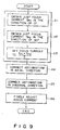
- Focusing is performed in step a1 to step a3 of Fig. 9.
- step a1 a just focus current f p1 in the 0° direction is obtained.
- step a2 a just focus current f p2 in the 90° direction is obtained.
- step a3 a value (f p1 + f p2 )/2 is obtained from the just focus current f p1 and f p2 , and a current value of the focus correction coil is set in (f p1 + f p2 )/2.
- step a4 astigmatism in the axial-direction is corrected using a rectangular beam.
- step a5 astigmatism in the diagonal-direction is performed using triangle beams.
- step a6 the focus current is finely adjusted to complete focus adjustment.
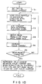
- step b1 an initial focus current is set.
- step b2 the gold particle is scanned with the shaped beam in a designated direction (0° or 90° direction).
- step b3 a back-scattered electron signal from the gold particle is A/D-converted.
- step b4 a beam resolution is obtained from the corresponding wave form data.
- step b5 the focus current is increased. It is then determined in step b6 whether a measurement of a relationship between the focus current and the beam resolution is completed.
- step b6 the flow returns to step b2.
- step b2 to step b5 are repeated until the relationship between the focus current and the beam resolution is completely measured.
- the relationship between the focus current and the beam resolution is represented by a quadratic function in step b7, and its peak value (-b/2a) is set in the focus coil as the just focus current. Therefore, the just focus current f p1 in the 0° direction and the just focus current f p2 in the 90° direction can be obtained.
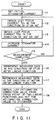
- step c1 an initial stigmator current is set.
- step c2 a just focus current f p1 in the 0° or 45° direction is obtained.
- step c3 a just focus current f p2 in the 90° or 135° direction is obtained.
- step c4 the stigmator current is increased. It is then determined in step c5 whether a measurement for obtaining a relationship between a corrected value of astigmatism and the just focus current is completed.
- step c5 If NO in step c5, the flow returns to step c2, and the operations in steps c2 to c4 are repeated. If YES in step c5, the flow advances to step c6 to represent the 0°- or 45°-direction measured data representing the relationship between the corrected value of astigmatism and the just focus current by a linear function. In step c7, the 90°- or 135°-direction measured data representing the relationship between the corrected value of astigmatism and the just focus current is represented by a linear function. The operations in steps c6 and c7 may be reversed. A just corrected value of astigmatism is obtained from a cross section of two lines and is set in the stigmator in step c8.
- equation (1) below is used in place of the beam resolution as a means for correcting a focus.
- the focus can be adjusted with higher precision at a higher speed.
- Fig. 12 shows a relationship between the accumulated sumnation value and the focus current.
- the basic flow of the second embodiment is the same as that shown in Fig. 10.
- a method of correcting astigmatism in the second embodiment is the same as that in Fig. 11.
- a characteristic feature of the second embodiment is a technique for calculating just focus current f p1 and f p2 , as will be described with reference to Fig. 14.
- step d1 an initial focus current is set in step d1.
- step d2 the gold particle is scanned with a shaped beam in a designated direction (0° or 90° direction).
- An electron signal back-scattered by the gold particle is A/D-converted in step d3.
- step d4 a wave form data signal is processed to obtain difference signal data, as shown in Figs. 12A to 12C.
- step d5 an accumulated summation value of the difference signal data equal to or more than a predetermined threshold level is obtained in step d5.
- steps d2 to d5 are continuously performed until the measurement is completed. If YES in step d6, the relationship between the focus current and the accumulated summation value is represented by a quadratic function, and the peak value (-b/2a) is set as a just focus current.
- Figs. 15A and 15B The third embodiment of the present invention will be described with reference to Figs. 15A and 15B.
- This embodiment exemplifies the following astigmatism correction.
- a focus is shifted by a predetermined value.
- Edge resolutions of a beam in the 0° and 90° directions are obtained while the corrected value of astigmatism is changed, thus obtaining a relationship shown in Fig. 15A.
- An accumulated summation value of difference signal data is obtained in place of the beam edge resolution to obtain a relationship shown in Fig. 15B.
- Relationships between the stigmator current and the beam edge resolutions, or between the stigmator current and the accumulated summation value of the difference signal data are measured in two orthogonal directions, e.g., in the 0° and 90° directions.
- the relationships of the measured values are represented by two quadratic functions, and a just corrected value of astigmatism is obtained by a cross point of the two quadratic functions, i.e., a point at which the edge resolutions or the accumulated summation values of the difference signal data in the 0° and 90° directions coincide with each other.
- This method is applicable to astigmatism correction in the 45° and 135° directions by using triangle beams.
- Fig. 16 shows a basic flow of the third embodiment.
- the focus correction is performed.
- the focus is obscured by a predetermined value in step e2.
- astigmatism of an axial-direction is corrected.
- astigmatism of a diagonal-direction is corrected.
- the operations in steps e3 and e4 may be reversed.
- a focus current is reset to an initial value in step e5.
- the focus current is finely adjusted.
- step f1 an initial stigmator current is set.
- step f2 a beam resolution or an accumulated summation value in the 0° or 45° direction is obtained.
- step f3 a beam resolution or an accumulated summation value in the 90° or 135° direction is obtained.
- step f4 the stigmator current is increased.
- step f6 the relationship between the stigmator current and the beam resolution obtained in the 0° or 45° direction or between the stigmator current and the accumulated summation value obtained in the 0° or 45° direction is represented by a quadratic function.
- step f7 the relationship between the stigmator current and the beam resolution obtained in the 90° or 135° direction or between the stigmator current and the accumulated summation value obtained in the 90° or 135° direction is represented by a quadratic function.
- the operations in steps f6 and f7 may be reversed.
- a cross point of the two quadratic functions is set in the astigmatism correction coil as a just astigmatism.
- the fourth embodiment of the present invention will be described with reference to Figs. 18, 19, and 20.
- This embodiment optimizes the focus adjustment and astigmatism correction sequence, thereby improving astigmatism correction.
- Wave form data shown in Fig. 18 is obtained by a rectangular beam.
- the wave form data are accumulatively summed with reference to a [(max + min)/2] threshold level.
- a peak value is obtained from a relationship between the focus and the accumulated sumnation value to coarsely adjust the focus.
- the focus is set at a position corresponding to (f p1 + f p2 )/2 in accordance with the relationship between the focus and the accumulated summation value of the difference signals shown in Figs. 12C and 13.
- Triangle beams are generated to correct astigmatism in the diagonal-direction, and then astigmatism in the axial-direction is corrected by the rectangular beam.
- a focus current corresponding to a zero focus difference obtained in astigmatism correction in the axial-direction is set in the focus coil.
- Fig. 19 shows a basic flow of the fourth embodiment.
- a focus point is coarsely adjusted.
- the focus is finely adjusted.
- astigmatism in the diagonal-direction is corrected using triangle beams.
- astigmatism in the axial-direction is corrected using a rectangular beam.
- the operations in steps g3 and g4 cannot be reversed.
- step g5 a focus current corresponding to a zero focus difference obtained from the astigmatism correction in axial direction is set in the focus adjustment coil.
- Fig. 20 is a flow of coarse focus adjustment of the fourth embodiment.
- step h1 an initial focus current is set in the focus adjustment.
- step h2 the gold particle is scanned with a shaped beam in a designated direction.
- a back-scattered electron signal from the gold particle upon its scanning is A/D-converted in step h3.
- step h4 a ⁇ (MAX + MIN)/2 ⁇ threshold level is set from the wave form data.
- An accumulated summation value of the wave form data equal to or more than this threshold level is obtained in step h5. If it is determined in step h6 that the above measurement is not completed, the flow returns to step h2.
- a series of operations in steps h2 to h5 are repeated until the measurement is completed.
- step h6 If YES in step h6, the flow advances to step h7.
- a relationship between the focus current and the accumulated summation value is represented by a quadratic function.
- a peak value is defined as a just focus current which is then set in the focus coil.
- each of the above embodiments exemplifies the electron beam lithographic apparatus.
- the present invention is also applicable to an ion beam lithographic apparatus.
- the arrangements of the optical systems and circuits are not limited to those in Fig. 1 and can be arbitrarily changed and modified in accordance with given technical specifications.
- an arrangement must have a function of shaping a rectangular beam having adjacent sides extending in, e.g., 0° and 90° directions and beams (e.g., two triangle beams) having sides oblique to the sides of the rectangular beam, e.g., sides extending in the 45° and 135° directions, and astigmatism correction coils for correcting astigmatism in the 0° and 90° direction and astigmatism in the 45° and 135° directions.
- beams e.g., two triangle beams
Landscapes
- Chemical & Material Sciences (AREA)
- Analytical Chemistry (AREA)
- Electron Beam Exposure (AREA)
- Exposure And Positioning Against Photoresist Photosensitive Materials (AREA)
Claims (18)
- Procédé de correction d'astigmatisme d'un faisceau dont la section a une forme variable, qui utilise un appareil de photogravure à faisceau de particules chargées ayant des première et seconde ouvertures de mise en forme, un déflecteur pour générer un faisceau mis en forme par une superposition optique, une bobine de correction de focalisation pour ajuster une focalisation du faisceau mis en forme, et des bobines de correction d'astigmatisme pour corriger l'astigmatisme du faisceau mis en forme,
le procédé comprenant les étapes de :
ajustage de focalisation du faisceau mis en forme en utilisant ladite bobine de correction de focalisation ; et
correction de l'astigmatisme du faisceau mis en forme en utilisant lesdites bobines de correction d'astigmatisme, l'étape de correction de l'astigmatisme du faisceau mis en forme comprenant les sous-étapes de :
mesure des premières résolutions de bord du faisceau mis en forme dans une première direction arbitraire et dans une seconde perpendiculaire à la première direction, et correction du premier astigmatisme dans les première et seconde directions sur la base des premières résolutions de bord, et
mesure d'une seconde résolution de bord dans une troisième direction oblique par rapport à la première direction et une quatrième direction perpendiculaire à la troisième direction, et correction du second astigmatisme dans les troisième et quatrième directions sur la base des secondes résolutions de bord. - Procédé selon la revendication 1 caractérisé en ce que l'étape de correction de l'astigmatisme du faisceau mis en forme comprend les sous-étapes de génération d'un faisceau rectangulaire ayant des côtés dans des première et seconde directions de 0° et 90° pour mesurer lesdites résolutions de bord dudit faisceau rectangulaire sur une cible et des faisceaux triangulaires ayant des côtés obliques s'étendant dans des troisième et quatrième directions de 45° et 135° pour mesurer lesdites secondes résolutions des faisceaux triangulaires et de la cible, et correction de l'astigmatisme dans les directions de 0° et 90° sur la base des premières résolutions de bord et de l'astigmatisme dans les directions de 45° à 135° sur la base des secondes résolutions de bord.
- Procédé selon la revendication 2, caractérisé en ce que ladite étape d'ajustage de focalisation du faisceau mis en forme comprend la sous-étape de balayage d'une marque sur la cible par un faisceau mis en forme, obtention des valeurs de focalisation exacte correspondant aux résolutions de bord minimum dans deux directions orthogonales alors que la valeur de courant de ladite bobine de correction de focalisation varie, et application de la valeur de focalisation exacte à ladite bobine de correction de focalisation ; et
l'étape de correction de l'astigmatisme comprend les sous-étapes de :
calcul d'une différence de focalisation dans les directions de 0° et 90° en utilisant un faisceau rectangulaire et une différence de focalisation dans la direction de 45° et 135° en utilisant des faisceaux triangulaires ayant des côtés obliques dans les directions de 45° et 135°, les différences de focalisation étant des différences entres des valeurs de focalisation exacte dans les deux directions, et
application des valeurs de courant auxdites bobines de correction d'astigmatisme pour que les différences de focalisation dans les deux directions soient nulles. - Procédé selon la revendication 3, caractérisé en ce que ladite étape d'application des valeurs de courant auxdites bobines de correction d'astigmatisme comprend les sous-étapes de :
variation de façon séquentielle des valeurs de courant desdites bobines de correction d'astigmatisme pour calculer la différence de focalisation entre la pluralité de valeurs de courant desdites bobines de correction d'astigmatisme ;
représentation de chaque relation de différences de focalisation par une fonction linéaire pour obtenir des valeurs de courant à appliquer auxdites bobines de correction d'astigmatisme à partir d'un point d'intersection entre les fonctions linéaires ; et
application des valeurs de courant résultantes aux bobines de correction d'astigmatisme. - Procédé selon la revendication 2, caractérisé en ce que ladite étape d'ajustage de focalisation du faisceau mis en forme comprend les sous-étapes de :
balayage d'une marque sur la cible par le faisceau de particules chargées alors qu'un courant passant à travers ladite bobine de correction de focalisation varie ;
détection des électrons rétrodiffusés ou secondaires rétrodiffusés par la marque et génération d'un signal de détection ; et
calcul d'un signal de différence (différentiel) entre des données d'onde obtenues par une conversion analogique - numérique du signal de détection, et des données obtenues en retardant les données d'onde, et d'une sommation accumulative des données de signal de différence non inférieures à une valeur de seuil prédéterminée, et obtention comme valeur de focalisation exacte d'un courant qui maximise la valeur accumulée de sommation. - Procédé selon la revendication 1, caractérisé en ce qu'il comprend en outre les étapes de :
décalage de la focalisation d'une valeur prédéterminée après l'étape d'ajustage de focalisation du faisceau mis en forme ;
obtention des résolutions de bord dans les deux directions orthogonales soumises à une correction de l'astigmatisme alors que les valeurs de courant desdites bobines de correction d'astigmatisme varient ; et
obtention d'une valeur corrigée d'astigmatisme lorsque les résolutions de bord dans les deux directions coïncident l'une avec l'autre. - Procédé selon la revendication 6, caractérisé en ce que ladite étape d'obtention de la valeur corrigée d'astigmatisme comprend la sous-étape de représentation d'une relation entre les valeurs de courant desdites bobines de correction d'astigmatisme et les résolutions de bord par des courbes quadratiques et obtention de la valeur corrigée d'astigmatisme par un point d'intersection de deux courbes.
- Procédé selon la revendication 6, caractérisé en ce qu'il comprend en outre les étapes de :
décalage de la focalisation d'une valeur prédéterminée après l'étape d'ajustage de la focalisation du faisceau mis en forme ;
obtention des valeurs accumulées de sommation dans deux directions orthogonales soumises à une correction de l'astigmatisme alors que les valeurs de courant desdites bobines de correction d'astigmatisme varient, l'étape d'obtention des valeurs accumulées de sommation dans les deux directions orthogonale comprend les sous-étapes de :
balayage d'une marque sur une cible par le faisceau de particules chargées alors que des courants passant à travers lesdites bobines de correction d'astigmatisme varient,
détection des électrons rétrodiffusés ou secondaires réfléchis par la marque et génération d'un signal de détection, et
calcul d'un signal de différence (différentiel) entre les données d'onde obtenues par une conversion analogique - numérique du signal de détection et les données obtenues en retardant les données d'onde, et d'une sommation accumulative des données de signal de différence non inférieures à un niveau de seuil prédéterminé ; et
obtention d'une valeur corrigée d'astigmatisme lorsque les valeurs accumulées de sommation dans les deux directions coïncident l'une avec l'autre. - Procédé selon la revendication 8, caractérisé en ce que ladite étape d'obtention de la valeur corrigée d'astigmatisme comprend la sous-étape de représentation d'une relation entre les valeurs de courant desdites bobines de correction d'astigmatisme et les valeurs accumulées de sommation par des courbes quadratiques, et obtention des valeurs corrigées d'astigmatisme par un point d'intersection des deux courbes.
- Procédé selon la revendication 2, caractérisé en ce qu'il comprend en outre les étapes de :
décalage de la focalisation d'une valeur prédéterminée après l'étape d'ajustage de la focalisation du faisceau mis en forme ;
obtention des résolutions de bord dans les deux directions orthogonales soumises à une correction de l'astigmatisme alors que les valeurs de courant desdites bobines de correction d'astigmatisme varient ; et
obtention d'une valeur corrigée d'astigmatisme lorsque les résolutions de bord dans les deux directions coïncident l'une avec l'autre. - Procédé selon la revendication 9, caractérisé en ce que ladite étape d'obtention de la valeur corrigée d'astigmatisme comprend la sous-étape de représentation d'une relation entre les valeurs de courant desdites bobines de correction d'astigmatisme et les résolutions de bord par des courbes quadratiques et obtention de la valeur corrigée d'astigmatisme par un point d'intersection des deux courbes.
- Procédé selon la revendication 2, caractérisé en ce qu'il comprend en outre les étapes de :
décalage de focalisation d'une valeur prédéterminée après l'étape d'ajustage de la focalisation du faisceau mis en forme ;
obtention des valeurs accumulées de sommation dans deux directions orthogonales soumises à une correction de l'astigmatisme alors que les valeurs de courant desdites bobines de correction d'astigmatisme varient, l'étape d'obtention des valeurs accumulées de sommation dans les deux directions orthogonales comprenant les sous-étapes de :
balayage d'une marque sur une cible par le faisceau de particules chargées alors que des courants passant à travers lesdites bobines de correction d'astigmatisme varient,
détection des électrons réfléchis ou secondaires réfléchis par la marque et génération d'un signal de détection, et
calcul d'un signal de différence (différentiel) entre les données d'onde obtenues par une conversion analogique - numérique du signal de détection et des données obtenues en retardant les données d'onde, et d'une sommation accumulative des données de signal de différence non inférieures à un niveau de seuil prédéterminé ; et
obtention d'une valeur corrigée d'astigmatisme lorsque les valeurs accumulées de sommation dans les deux directions coïncident l'une avec l'autre. - Procédé selon la revendication 12, caractérisé en ce que ladite étape d'obtention de la valeur corrigée d'astigmatisme comprend la sous-étape de représentation d'une relation entre les valeurs de courant desdites bobines de correction d'astigmatisme et les valeurs accumulées de sommation par des courbes quadratiques, et obtention de la valeur corrigée d'astigmatisme par un point d'intersection des deux courbes.
- Procédé selon la revendication 2, caractérisé en ce que ladite étape d'ajustage de la focalisation du faisceau mis en forme comprend les sous-étapes de :
balayage d'une marque sur la cible par le faisceau de particules chargées alors qu'un courant passant à travers ladite bobine de correction de focalisation varie ;
détection des électrons réfléchis ou secondaires réfléchis par la marque et génération d'un signal de détection ; et
sommation accumulative des données d'onde obtenues par une conversion analogique - numérique du signal de détection, qui ne sont pas inférieures à un niveau de seuil prédéterminé, et obtention comme valeur de focalisation exacte d'un courant qui maximise la valeur accumulée de sommation. - Procédé selon la revendication 14, caractérisé en ce que ledit niveau de seuil est une valeur moyenne des valeurs maximum et minimum des données d'onde.
- Procédé selon la revendication 1, caractérisé en ce que lesdites résolutions de bord des faisceaux mis en forme ayant des surfaces égales sont utilisées pour réaliser un ajustage de focalisation ou une correction de l'astigmatisme.
- Procédé selon la revendication 1, caractérisé en ce que les valeurs accumulées de sommation des faisceaux mis en forme ayant des surfaces égales sont utilisées pour ajuster la focalisation, les valeurs accumulées de sommation étant obtenues par les étapes de :
balayage d'une marque sur la cible par le faisceau de particules chargées alors que des courants passant à travers lesdites bobines de correction de focalisation varient,
détection des électrons réfléchis ou secondaires réfléchis par la marque et génération d'un signal de détection, et
calcul d'un signal de différence (différentiel) entre les données d'onde obtenues par une conversion analogique - numérique du signal de détection et les données obtenues en retardant les données d'onde, et d'une sommation accumulative des données de signal de différence non inférieures à un niveau de seuil prédéterminé. - Procédé selon la revendication 1, caractérisé en ce que les valeurs accumulées de sommation des faisceaux mis en forme ayant des surfaces égales sont utilisées pour corriger l'astigmatisme, les valeurs accumulées de sommation étant obtenues par les étapes de :
balayage d'une marque sur une cible par le faisceau de particules chargées alors que des courants passant à travers lesdites bobines de correction d'astigmatisme varient,
détection des électrons réfléchis ou secondaires réfléchis par la marque et génération d'un signal de détection, et
calcul d'un signal de différence (différentiel) entre des données d'onde obtenues par une conversion analogique - numérique du signal de détection et des données obtenues en retardant les données d'onde, et d'une sommation accumulative des données de signal de différence non inférieures à un niveau de seuil prédéterminé.
Applications Claiming Priority (2)
| Application Number | Priority Date | Filing Date | Title |
|---|---|---|---|
| JP1243313A JP2835097B2 (ja) | 1989-09-21 | 1989-09-21 | 荷電ビームの非点収差補正方法 |
| JP243313/89 | 1989-09-21 |
Publications (3)
| Publication Number | Publication Date |
|---|---|
| EP0419287A2 EP0419287A2 (fr) | 1991-03-27 |
| EP0419287A3 EP0419287A3 (en) | 1992-01-02 |
| EP0419287B1 true EP0419287B1 (fr) | 1995-11-15 |
Family
ID=17101977
Family Applications (1)
| Application Number | Title | Priority Date | Filing Date |
|---|---|---|---|
| EP90310390A Expired - Lifetime EP0419287B1 (fr) | 1989-09-21 | 1990-09-21 | Méthode de correction de l'astigmatisme d'un faisceau dont la section présente une forme variable |
Country Status (4)
| Country | Link |
|---|---|
| US (1) | US5047646A (fr) |
| EP (1) | EP0419287B1 (fr) |
| JP (1) | JP2835097B2 (fr) |
| DE (1) | DE69023592T2 (fr) |
Families Citing this family (23)
| Publication number | Priority date | Publication date | Assignee | Title |
|---|---|---|---|---|
| US5172331A (en) * | 1989-12-18 | 1992-12-15 | Fujitsu Limited | Apparatus and method for effecting exposure of sample to charged particle beam |
| US5283440A (en) * | 1990-10-05 | 1994-02-01 | Hitachi, Ltd. | Electron beam writing system used in a cell projection method |
| US5304811A (en) * | 1991-08-09 | 1994-04-19 | Fujitsu Ltd. | Lithography system using charged-particle beam and method of using the same |
| US5391886A (en) * | 1991-08-09 | 1995-02-21 | Fujitsu Limited | Charged particle beam exposure system and method of exposing a pattern on an object by such a charged particle beam exposure system |
| US5389858A (en) * | 1992-07-16 | 1995-02-14 | International Business Machines Corporation | Variable axis stigmator |
| JP3402868B2 (ja) * | 1995-09-14 | 2003-05-06 | 株式会社東芝 | 荷電粒子光学鏡筒における非点収差の補正及び焦点合わせ方法 |
| US20060060781A1 (en) * | 1997-08-11 | 2006-03-23 | Masahiro Watanabe | Charged-particle beam apparatus and method for automatically correcting astigmatism and for height detection |
| US6025600A (en) * | 1998-05-29 | 2000-02-15 | International Business Machines Corporation | Method for astigmatism correction in charged particle beam systems |
| DE19827819C2 (de) * | 1998-06-17 | 2003-07-03 | Equicon Software Gmbh Jena | Verfahren zur Steuerung von Elektronenstrahl-Belichtungsanlagen mit Formstrahlprinzip |
| US6825480B1 (en) * | 1999-06-23 | 2004-11-30 | Hitachi, Ltd. | Charged particle beam apparatus and automatic astigmatism adjustment method |
| WO2002013227A1 (fr) * | 2000-07-27 | 2002-02-14 | Ebara Corporation | Appareil d'analyse a faisceau plan |
| US7062091B2 (en) * | 2001-01-16 | 2006-06-13 | Applied Precision, Llc | Coordinate calibration for scanning systems |
| JP4006216B2 (ja) | 2001-10-26 | 2007-11-14 | 日本電子株式会社 | 可変面積型電子ビーム描画装置を用いた描画方法 |
| JP4158199B2 (ja) * | 2004-01-30 | 2008-10-01 | 株式会社島津製作所 | Tftアレイ検査装置 |
| JP4299293B2 (ja) * | 2005-11-17 | 2009-07-22 | 株式会社ニューフレアテクノロジー | 荷電ビーム描画装置 |
| JP4801996B2 (ja) * | 2006-01-05 | 2011-10-26 | 株式会社ニューフレアテクノロジー | 試料移動機構及び荷電粒子ビーム描画装置 |
| KR101350980B1 (ko) * | 2007-12-31 | 2014-01-15 | 삼성전자주식회사 | Cd 선형성을 보정할 수 있는 가변 성형 빔을 이용한 노광방법 및 이를 이용한 패턴 형성 방법 |
| JP2011171009A (ja) * | 2010-02-16 | 2011-09-01 | Sii Nanotechnology Inc | 集束イオンビーム装置 |
| US8760563B2 (en) | 2010-10-19 | 2014-06-24 | Hand Held Products, Inc. | Autofocusing optical imaging device |
| US8692927B2 (en) | 2011-01-19 | 2014-04-08 | Hand Held Products, Inc. | Imaging terminal having focus control |
| JP6349944B2 (ja) * | 2014-05-13 | 2018-07-04 | 株式会社ニューフレアテクノロジー | 電子ビーム描画装置及び電子ビーム描画方法 |
| JP7200062B2 (ja) * | 2019-07-26 | 2023-01-06 | 日本電子株式会社 | 荷電粒子ビーム装置 |
| CN116441562B (zh) * | 2023-06-16 | 2023-08-15 | 西安赛隆增材技术股份有限公司 | 一种电子束的束斑的校准装置及校准方法 |
Family Cites Families (14)
| Publication number | Priority date | Publication date | Assignee | Title |
|---|---|---|---|---|
| US4090077A (en) * | 1969-03-05 | 1978-05-16 | Siemens Aktiengesellschaft | Particle beam device with a deflection system and a stigmator |
| GB2002547B (en) * | 1977-07-30 | 1982-01-20 | Tee W | Investigation of astigmatism in electron beam probe instruments |
| JPS5613649A (en) * | 1979-07-12 | 1981-02-10 | Akashi Seisakusho Co Ltd | Correcting method and device for astigmatism in scanning type electron microscope and the like |
| JPS5693318A (en) * | 1979-12-10 | 1981-07-28 | Fujitsu Ltd | Electron beam exposure device |
| JPS56147350A (en) * | 1980-04-16 | 1981-11-16 | Nichidenshi Tekunikusu:Kk | Correction method and performing device of astigmatism |
| GB2123582B (en) * | 1982-06-18 | 1986-01-29 | Nat Res Dev | Correction of astigmatism in electron beam instruments |
| JPS60147117A (ja) * | 1984-01-10 | 1985-08-03 | Fujitsu Ltd | 電子ビ−ム装置の調整方法 |
| JPH0793253B2 (ja) * | 1986-10-31 | 1995-10-09 | 株式会社東芝 | 荷電ビ−ム露光装置 |
| GB2197751A (en) * | 1986-11-24 | 1988-05-25 | Philips Electronic Associated | Variable shaped spot electron beam pattern generator |
| JPS63200444A (ja) * | 1987-02-16 | 1988-08-18 | Jeol Ltd | 走査型電子顕微鏡等の自動非点収差補正方法 |
| JPH0756786B2 (ja) * | 1988-03-09 | 1995-06-14 | 株式会社日立製作所 | 電子顕微鏡の焦点合わせ装置 |
| JP2786660B2 (ja) | 1989-03-31 | 1998-08-13 | 株式会社東芝 | 荷電ビーム描画方法 |
| JP2786662B2 (ja) | 1989-03-31 | 1998-08-13 | 株式会社東芝 | 荷電ビーム描画方法 |
| JP2786661B2 (ja) | 1989-03-31 | 1998-08-13 | 株式会社東芝 | 荷電ビーム描画方法 |
-
1989
- 1989-09-21 JP JP1243313A patent/JP2835097B2/ja not_active Expired - Fee Related
-
1990
- 1990-08-20 US US07/570,024 patent/US5047646A/en not_active Expired - Lifetime
- 1990-09-21 EP EP90310390A patent/EP0419287B1/fr not_active Expired - Lifetime
- 1990-09-21 DE DE69023592T patent/DE69023592T2/de not_active Expired - Fee Related
Also Published As
| Publication number | Publication date |
|---|---|
| EP0419287A2 (fr) | 1991-03-27 |
| EP0419287A3 (en) | 1992-01-02 |
| JPH03108312A (ja) | 1991-05-08 |
| US5047646A (en) | 1991-09-10 |
| DE69023592T2 (de) | 1996-03-28 |
| DE69023592D1 (de) | 1995-12-21 |
| JP2835097B2 (ja) | 1998-12-14 |
Similar Documents
| Publication | Publication Date | Title |
|---|---|---|
| EP0419287B1 (fr) | Méthode de correction de l'astigmatisme d'un faisceau dont la section présente une forme variable | |
| JP5090887B2 (ja) | 電子ビーム描画装置の描画方法及び電子ビーム描画装置 | |
| KR102432752B1 (ko) | 멀티 하전 입자 빔 묘화 장치 및 멀티 하전 입자 빔 묘화 방법 | |
| US7511272B2 (en) | Method for controlling charged particle beam, and charged particle beam apparatus | |
| US6207965B1 (en) | Apparatus and method for electron beam lithography and semiconductor device | |
| JP3105670B2 (ja) | 荷電粒子ビーム露光装置及びその制御方法 | |
| JPH06124883A (ja) | 荷電ビーム補正方法及びマーク検出方法 | |
| US20210398770A1 (en) | Charged Particle Beam Apparatus | |
| US8008631B2 (en) | Method of acquiring offset deflection amount for shaped beam and lithography apparatus | |
| KR20190044508A (ko) | 하전 입자 빔 묘화 장치 및 하전 입자 빔 묘화 방법 | |
| EP0023810B1 (fr) | Procédé d'exposition d'un faisceau électronique | |
| US4891524A (en) | Charged particle beam exposure system and method of compensating for eddy current effect on charged particle beam | |
| US4684809A (en) | Method of adjusting optical column in energy beam exposure system | |
| JP3522045B2 (ja) | 荷電粒子ビーム露光装置及びその方法 | |
| US7049611B2 (en) | Charged-particle beam lithographic system | |
| US10211027B2 (en) | Method for measuring resolution of charged particle beam and charged particle beam drawing apparatus | |
| JP2786660B2 (ja) | 荷電ビーム描画方法 | |
| JP4980829B2 (ja) | 電子ビーム描画装置のビーム位置補正方法及び装置 | |
| JP3357181B2 (ja) | 電子線描画装置およびその調整方法 | |
| JP2786662B2 (ja) | 荷電ビーム描画方法 | |
| JP2002246303A (ja) | 焦点調整方法及び電子線描画装置 | |
| JP3101100B2 (ja) | 電子ビーム露光装置 | |
| JPH11224642A (ja) | 電子ビーム露光装置および電子ビーム露光方法 | |
| JP2786661B2 (ja) | 荷電ビーム描画方法 | |
| JPH10163089A (ja) | 電子線描画装置 |
Legal Events
| Date | Code | Title | Description |
|---|---|---|---|
| PUAI | Public reference made under article 153(3) epc to a published international application that has entered the european phase |
Free format text: ORIGINAL CODE: 0009012 |
|
| 17P | Request for examination filed |
Effective date: 19901011 |
|
| AK | Designated contracting states |
Kind code of ref document: A2 Designated state(s): DE FR GB |
|
| PUAL | Search report despatched |
Free format text: ORIGINAL CODE: 0009013 |
|
| AK | Designated contracting states |
Kind code of ref document: A3 Designated state(s): DE FR GB |
|
| 17Q | First examination report despatched |
Effective date: 19940317 |
|
| GRAA | (expected) grant |
Free format text: ORIGINAL CODE: 0009210 |
|
| AK | Designated contracting states |
Kind code of ref document: B1 Designated state(s): DE FR GB |
|
| REF | Corresponds to: |
Ref document number: 69023592 Country of ref document: DE Date of ref document: 19951221 |
|
| ET | Fr: translation filed | ||
| PLBE | No opposition filed within time limit |
Free format text: ORIGINAL CODE: 0009261 |
|
| STAA | Information on the status of an ep patent application or granted ep patent |
Free format text: STATUS: NO OPPOSITION FILED WITHIN TIME LIMIT |
|
| 26N | No opposition filed | ||
| REG | Reference to a national code |
Ref country code: GB Ref legal event code: 746 Effective date: 19980915 |
|
| REG | Reference to a national code |
Ref country code: FR Ref legal event code: D6 |
|
| REG | Reference to a national code |
Ref country code: GB Ref legal event code: IF02 |
|
| PGFP | Annual fee paid to national office [announced via postgrant information from national office to epo] |
Ref country code: FR Payment date: 20050823 Year of fee payment: 16 |
|
| PGFP | Annual fee paid to national office [announced via postgrant information from national office to epo] |
Ref country code: DE Payment date: 20050915 Year of fee payment: 16 |
|
| PGFP | Annual fee paid to national office [announced via postgrant information from national office to epo] |
Ref country code: GB Payment date: 20050921 Year of fee payment: 16 |
|
| PG25 | Lapsed in a contracting state [announced via postgrant information from national office to epo] |
Ref country code: DE Free format text: LAPSE BECAUSE OF NON-PAYMENT OF DUE FEES Effective date: 20070403 |
|
| GBPC | Gb: european patent ceased through non-payment of renewal fee |
Effective date: 20060921 |
|
| REG | Reference to a national code |
Ref country code: FR Ref legal event code: ST Effective date: 20070531 |
|
| PG25 | Lapsed in a contracting state [announced via postgrant information from national office to epo] |
Ref country code: GB Free format text: LAPSE BECAUSE OF NON-PAYMENT OF DUE FEES Effective date: 20060921 |
|
| PG25 | Lapsed in a contracting state [announced via postgrant information from national office to epo] |
Ref country code: FR Free format text: LAPSE BECAUSE OF NON-PAYMENT OF DUE FEES Effective date: 20061002 |