EP0419315B1 - Bewegungsdetektionsverfahren mit der gewünschten Hochbildfrequenz und Zeilenzahl sowie Einrichtung zur Durchführung dieses Verfahrens - Google Patents
Bewegungsdetektionsverfahren mit der gewünschten Hochbildfrequenz und Zeilenzahl sowie Einrichtung zur Durchführung dieses Verfahrens Download PDFInfo
- Publication number
- EP0419315B1 EP0419315B1 EP19900402464 EP90402464A EP0419315B1 EP 0419315 B1 EP0419315 B1 EP 0419315B1 EP 19900402464 EP19900402464 EP 19900402464 EP 90402464 A EP90402464 A EP 90402464A EP 0419315 B1 EP0419315 B1 EP 0419315B1
- Authority
- EP
- European Patent Office
- Prior art keywords
- output
- motion
- lines
- input
- circuit
- Prior art date
- Legal status (The legal status is an assumption and is not a legal conclusion. Google has not performed a legal analysis and makes no representation as to the accuracy of the status listed.)
- Expired - Lifetime
Links
- 238000000034 method Methods 0.000 title claims description 7
- 238000001514 detection method Methods 0.000 title description 20
- 230000015654 memory Effects 0.000 claims description 38
- 238000001914 filtration Methods 0.000 claims description 7
- 210000004027 cell Anatomy 0.000 description 12
- 238000006243 chemical reaction Methods 0.000 description 6
- 230000006870 function Effects 0.000 description 3
- 238000004364 calculation method Methods 0.000 description 2
- 238000010586 diagram Methods 0.000 description 2
- 230000006872 improvement Effects 0.000 description 2
- 230000003068 static effect Effects 0.000 description 2
- 230000001360 synchronised effect Effects 0.000 description 2
- 241001080024 Telles Species 0.000 description 1
- 230000009471 action Effects 0.000 description 1
- 230000008569 process Effects 0.000 description 1
- 239000004065 semiconductor Substances 0.000 description 1
- 210000000352 storage cell Anatomy 0.000 description 1
- 230000001131 transforming effect Effects 0.000 description 1
Images

Classifications
-
- H—ELECTRICITY
- H04—ELECTRIC COMMUNICATION TECHNIQUE
- H04N—PICTORIAL COMMUNICATION, e.g. TELEVISION
- H04N5/00—Details of television systems
- H04N5/14—Picture signal circuitry for video frequency region
- H04N5/144—Movement detection
Definitions
- the present invention relates to a motion detection method at the frame frequency and the number of desired lines as well as a device for its implementation. It relates more particularly to an improvement to the motion detection method and device described in the German patent application DE-A-38 09 249 in the name of Irish Thomson Brandt and in the French patent application N ° 89 03861 in the name of the Laboratory European Advanced Electronic Research (LEREA). In French patent application No.
- 89 03861 (FR-A-2 644 956) of 03/23/89 in the name of the Applicant, published on September 28, 1990, a device has been described making it possible to convert the video signals received into input from a high definition television receiver, including decoded 1250/2: 1 / 50Hz HD-MAC input signals or 625/2: 1 / 50Hz PAL, SECAM or MAC signals decoded into a high display signal definition, namely a signal allowing display on 1250 lines or 900 lines with 2: 1 interlacing at a frame frequency of 100Hz.
- This frame frequency conversion device includes a device for processing static type input signals and a device for processing dynamic type input signals. Switching between the dynamic type input signal processing device and the static type input signal processing device is controlled by a motion detection signal.
- the motion detection signal comes from a specific circuit called detector of movement.
- detector of movement Such a circuit is described in particular in the German patent application N ° 38 09 249 in the name of Deutsche Thomson Brandt or in the French patent application N ° 89 03861 in the name of LEREA
- the motion detection signal from the circuits described in these applications allows a display frequency of 100Hz on 1250 lines .
- the display is a 900/2: 1 / 100Hz type display, the motion detection signal is no longer synchronous with the display video signal.
- the object of the present invention is to propose an improvement to the motion detection method described in the patents mentioned above, which makes it possible to use the motion detection information during a high definition display of the 900 type. / 2: 1 / 100Hz.
- the present invention also aims to provide a device for transforming the conventional motion detector into a device giving a motion detection signal at the frame frequency and the desired number of lines.
- Another object of the present invention is to propose a motion detection device which can be used for a display of the 1250/2: 1 / 100Hz, 900/2: 1 / 100Hz type or having different characteristics in terms of the number of lines. .
- the subject of the present invention is a motion detection method giving motion information at the frame frequency and the number of desired lines, characterized in that it consists in applying to the level of the image points of the same corresponding spatial position.
- the following algorithm to two temporally different images given by a signal at the frame frequency and the number of lines of the input video signal, the following algorithm: (with y an integer corresponding to adjacent line addresses around a reference line, n and n-1 to two temporally different images and K y to the coefficient of vertical filtering of the line considered), - Then compare the value obtained DP on with a threshold value and send movement or non-movement information according to the result of the comparison.
- final movement information is obtained by taking a majority decision on the movement information given by several images of different spatial position belonging to the same image line.
- the memories are written in parallel with the frame frequency of the input signal and are read in parallel with the frame frequency of the signal output, writing and reading being performed under control of specific write and read command signals.
- the vertical filtering circuit consists of n delay cells giving a delay of a memory line, n + 1 multipliers each receiving on one input a specific multiplier coefficient and on the other input, ie the input of the first cell, ie the output of the n cells, a first adder adding the output of the first two multipliers and n adders adding the output of the preceding adder and that of the multiplier of rank n + 1.
- the display can be carried out on 1250 lines, 900 lines or on a different number of lines.
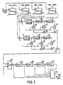
- the motion detection device comprises four frame memories 1, 2, 3, 4 making it possible to detect a movement between two images contained in a video signal at input E of type 625 / 2: 1 / 50Hz PAL, SECAM, MAC or similar.
- Each frame memory 1, 2, 3, 4 has a capacity of 288 x 720 x 8 (288 corresponding to the useful lines, 720 to the number of image points or useful pixels per line and 8 to the number of coding bits of each pixel) .
- the memories 1, 2, 3, 4 are written in parallel under the command of a write pulse and are read in parallel under the command of a read pulse.
- memories 1, 2, 3, 4 can be connected in series. In this case, it is necessary to use at least one additional memory to perform the 50Hz / 100Hz conversion.
- a first image (n) is stored in the odd frame memory 1 and the even frame memory 2 while a second image (n - 1) is subsequently stored in the memory of odd frame 3 and even frame memory 4. Storage is carried out, for example, as shown in FIG. 2.
- Signal E corresponds to an input video signal of type 625/2: 1 / 50Hz and represents the successive frames A, B, C, D, E, F, etc ... whose duration is 20 milliseconds.
- the odd frames A, C, E are stored in the frame memories 1 and 3 so that the frames A and E are stored in the memory 1, and the frame C in the memory 3.
- even frames B, D, F are stored in memories 2 and 4 so that frames B and F are stored in memory 2, and frame D in memory 4.
- have memories 1, 2, 3 , 4 are read at a frequency of 100Hz, i.e. in 10 milliseconds.
- memories 1, 2, 3, 4, eight frames A or B or C or D, ... are each maintained for 10 milliseconds.
- the motion detection device according to the present invention is used in a frame frequency conversion device as described in French patent application No. 89 03861, the memories 1, 2, 3, 4 are already part of the device frequency conversion. This makes it possible to reduce the memory capacity necessary for the whole of the device and thus to decrease the surface of semiconductor necessary for the realization of a television set.
- Each circuit at the output of circuits 6, 6 ' is identical. It consists of two delay cells 70, 71 or 70 ', 71'. Each cell has a delay of one line.
- the circuit includes three multipliers 80, 81, 82 or 80 ', 81', 82 '.
- the multipliers 80, 81, 82 or 80 ', 81', 82 ' receive respectively on one of their inputs a specific multiplier coefficient under the action of a control pulse C.
- the multiplier 80 or 80' receives on its other input the output of the 6 or 6 'absolute value circuit.
- the other multipliers 81 and 82 receive on their other inputs respectively the output of the delay cells 70, 71 or 70 ', 71'.
- the circuit includes two adders 90, 91, 90 ', 91'.
- the circuit 90 receives respectively the outputs of the multipliers 80, 81, 80 ', 81' while the adder 91, 91 'receives respectively on its inputs the outputs of the adder 90 or 90' and of the multiplier 82 or 82 '.
- the number of cells of the above circuit is in fact a function of the number of lines which it is desired to weight for the application of the motion detection method according to the present invention.
- the output of the adder 100 is sent to the input of the comparator 101 which compares the value A obtained with a threshold value B, giving at output "1" if A is greater than B, and "0" if A is less than or equal to B.
- the outputs of comparator 101 are sent in series in storage cells 102, 103, 104, 105 achieving a delay corresponding to the calculation of a DP on , so that after five calculations of DP on , a comparison is made in majority logic 106 so as to send majority movement information as a function of the five movement information, for example information of movement "1" if three of the movement information items from cells 102, 103, 104, 105 and comparator 101 are coded by "1".
- This motion information is used in particular by a frequency conversion device as described in French patent application No. 89 03861.
- a system has been described which performs motion detection using six memory lines. It is obvious to a person skilled in the art that by varying the number of delay cells 70, 71 or 70 ', 71' and / or possibly the number of delay cells 102, 103, 104, 105 , the movement information will be detected with more or less precision. In practice, it seems advantageous to detect the movement information based on a movement detection carried out for five adjacent lines and five adjacent points.
- the display can be carried out on a number of lines other than 900 lines, in particular 1250 lines, using the same motion detection device.
Landscapes
- Engineering & Computer Science (AREA)
- Multimedia (AREA)
- Signal Processing (AREA)
- Television Systems (AREA)
Claims (7)
- Bewegungsdetektionsverfahren, das eine Bewegungsinformation mit der gewünschten Teilbildfrequenz und Zeilenzahl ergibt, dadurch gekennzeichnet, daß es darin besteht, auf der Stufe der Bildpunkte mit der gleichen räumlichen Position, die zwei zeitlich unterschiedlichen Bildern entsprechen, die durch ein Signal mit der Teilbildfrequenz und der Zeilenzahl des Eingangs-Videosignals gegeben sind, und den folgenden Algorithmus anzuwenden:

dann den den erhaltenen Wert DPon mit einem Schwellenwert zu vergleichen und eine Information der Bewegung oder der Nichtbewegung abhängig vom Ergebnis des Vergleichs abzugeben. - Verfahren nach Anspruch 1, dadurch gekennzeichnet, daß der Algorithmus unter Verwendung der Punktbilder angewendet wird, die zu fünf aufeinanderfolgenden Bildzeilen gehören.
- Verfahren nach einem der Ansprüche 1 und 2, dadurch gekennzeichnet, daß eine End-Bewegungsinformation erhalten wird, in dem eine Majoritätsentscheidung über die Bewegungsinformationen getroffen wird, die durch mehrere einer gleichen Bildzeile angehörenden Bildpunkten mit unterschiedlicher räumlicher Position gegeben sind.
- Vorrichtung zur Durchführung des Verfahrens nach einem der Ansprüche 1 bis 3, dadurch gekennzeichnet, daß es enthält:- wenigstens vier Teilbildspeicher (1, 2, 3, 4) zum Speichern der geradzahligen und ungeradzahligen Teilbilder von zwei aufeinanderfolgenden Bildern,- zwei gleiche Verarbeitungsschaltungen (5, 6, 70, 71, 80, 81, 82, 90, 91 und 5', 6', 70', 71', 80', 81', 82', 90', 91'), die jeweils am Ausgang der Speicher gerader Teilbilder und der Speicher ungerader Teilbilder angeschlossen sind, wobei jede Schaltung von einer Subtrahiereinheit, einem Absolutwertdetektor und einer Vertikalfilterschaltung gebildet ist,- eine Addiereinheit (100), die die Ausgangssignale der zwei Verarbeitungsschaltungen empfängt, und- einen Komparator (101), der das Ausgangssignal der Addiereinheit mit einem Schwellenwert zur Abgabe einer Bewegungsinformation vergleicht.
- Vorrichtung nach Anspruch 4, dadurch gekennzeichnet, daß sie ferner ent hält:- n Verzögerungszellen (102, 103, 104, 105) (n>1), die am Ausgang des Komparators angeschlossen sind, und- eine Logikschaltung (106), die die Ausgangssignale des Komparators und der n Verzögerungszellen empfängt und eine Majoritätsentscheidung in der Weise trifft, daß eine End-Bewegungsinformation abgegeben wird.
- Vorrichtung nach einem der Ansprüche 4 und 5, dadurch gekennzeichnet, daß das Schreiben in die Speicher parallel mit der Teilbildfrequenz des Eingangssignals erfolgt und das Lesen mit der Teilbildfrequenz des Ausgangssignals erfolgt, wobei das Schreiben und das Lesen unter der Steuerung durch spezielle Schreib- und Lesesteuersignale erfolgt.
- Vorrichtung nach einem der Ansprüche 4 bis 6, dadurch gekennzeichnet, daß die Vertikalfilterschaltung gebildet ist aus n Verzögerungszellen (70, 71 und 70', 71'), die eine Verzögerung um eine Speicherzeile ergeben, n+1 Multipliziereinheiten (80, 81, 82 und 80', 81', 82'), die an einem Eingang jeweils einen speziellen Multiplikationskoeffizienten und am anderen Eingang entweder das Eingangssignal der ersten Zelle oder das Ausgangssignal von n Zellen empfängt, eine erste Addiereinheit (90 und 90'), die das Ausgangssignal der zwei ersten Multipliziereinheiten addiert, sowie n Addiereinheiten (91 und 91'), die das Ausgangssignal der vorhergehenden Addiereinheit und der Multipliziereinheit der Rangordnung n+1 empfängt.
Applications Claiming Priority (2)
| Application Number | Priority Date | Filing Date | Title |
|---|---|---|---|
| FR8911752A FR2651948B1 (fr) | 1989-09-08 | 1989-09-08 | Procede de detection de mouvement a la frequence trame et au nombre de lignes souhaites et dispositif pour sa mise en óoeuvre. |
| FR8911752 | 1989-09-08 |
Publications (2)
| Publication Number | Publication Date |
|---|---|
| EP0419315A1 EP0419315A1 (de) | 1991-03-27 |
| EP0419315B1 true EP0419315B1 (de) | 1994-03-30 |
Family
ID=9385251
Family Applications (1)
| Application Number | Title | Priority Date | Filing Date |
|---|---|---|---|
| EP19900402464 Expired - Lifetime EP0419315B1 (de) | 1989-09-08 | 1990-09-07 | Bewegungsdetektionsverfahren mit der gewünschten Hochbildfrequenz und Zeilenzahl sowie Einrichtung zur Durchführung dieses Verfahrens |
Country Status (4)
| Country | Link |
|---|---|
| EP (1) | EP0419315B1 (de) |
| DE (1) | DE69007724T2 (de) |
| ES (1) | ES2050977T3 (de) |
| FR (1) | FR2651948B1 (de) |
Families Citing this family (1)
| Publication number | Priority date | Publication date | Assignee | Title |
|---|---|---|---|---|
| DE4327779C1 (de) * | 1993-08-18 | 1994-12-08 | Siemens Ag | Verfahren und Schaltungsanordnung für ein Fernsehgerät zur Verminderung des Flimmerns |
Family Cites Families (4)
| Publication number | Priority date | Publication date | Assignee | Title |
|---|---|---|---|---|
| GB2031686B (en) * | 1978-09-14 | 1983-02-02 | Micro Consultants Ltd | Movement detection |
| DE3886144T2 (de) * | 1987-08-28 | 1994-07-14 | British Telecomm | Kodierung von Signalen. |
| FR2623040B1 (fr) * | 1987-11-09 | 1990-02-09 | France Etat | Procede et dispositif de traitement de signaux d'image a balayage de trame entrelace |
| DE3803835A1 (de) * | 1988-02-09 | 1989-08-17 | Thomson Brandt Gmbh | Transcoder |
-
1989
- 1989-09-08 FR FR8911752A patent/FR2651948B1/fr not_active Expired - Fee Related
-
1990
- 1990-09-07 ES ES90402464T patent/ES2050977T3/es not_active Expired - Lifetime
- 1990-09-07 EP EP19900402464 patent/EP0419315B1/de not_active Expired - Lifetime
- 1990-09-07 DE DE1990607724 patent/DE69007724T2/de not_active Expired - Fee Related
Also Published As
| Publication number | Publication date |
|---|---|
| EP0419315A1 (de) | 1991-03-27 |
| ES2050977T3 (es) | 1994-06-01 |
| DE69007724T2 (de) | 1994-08-04 |
| FR2651948B1 (fr) | 1995-07-28 |
| DE69007724D1 (de) | 1994-05-05 |
| FR2651948A1 (fr) | 1991-03-15 |
Similar Documents
| Publication | Publication Date | Title |
|---|---|---|
| EP0640908B1 (de) | Reduzierung des Rauschens in Bildsignalen | |
| Graham | Image transmission by two-dimensional contour coding | |
| US4953114A (en) | Image signal processing apparatus | |
| US4549212A (en) | Image processing method using a collapsed Walsh-Hadamard transform | |
| US20040189875A1 (en) | Processing a video signal using motion estimation to separate luminance information from chrominance information in the video signal | |
| GB2182521A (en) | Image motion detector for video signals | |
| FR2633137A1 (fr) | Systeme d'emission et reception de television a haute definition a estimateur de vitesses ameliore et a debit de donnees reduit | |
| US5406501A (en) | Method and device for use in detecting moving targets | |
| FR2651402A1 (fr) | Dispositif de conversion de frequence trame et du nombre de lignes pour un recepteur de television haute definition. | |
| EP0412003B1 (de) | Vorrichtung zur Umwandlung einer Bewegungsinformation in ein Bewegungsdetektionssignal mit gewünschter Zeilenanzahl und Halbbildfrequenz für einen Hochauflösungsfernsehempfänger | |
| FR2501944A1 (fr) | Dispositif pour la conversion du nombre de lignes de balayage | |
| US5206715A (en) | Circuit for separating luminance and chrominance signals | |
| FR2493086A1 (fr) | Correcteur de la chute hors limites d'un signal et procedes de compensation et de detection de chutes hors limites dans un signal | |
| US5416532A (en) | Adaptive video peaking circuitry using cross-faders | |
| EP0419315B1 (de) | Bewegungsdetektionsverfahren mit der gewünschten Hochbildfrequenz und Zeilenzahl sowie Einrichtung zur Durchführung dieses Verfahrens | |
| EP0294282B1 (de) | Verfahren zur temporalen Interpolation von Bildern und Einrichtung zur Durchführung dieses Verfahrens | |
| JP3486975B2 (ja) | ノイズ低減装置及び方法 | |
| BE898283A (fr) | Procédé pour le filtrage en peigne d'un signal composite de télévision et filtre en peigne à utiliser. | |
| JPS626273B2 (de) | ||
| EP0391760B1 (de) | Einrichtung zur Umwandlung der Bildfrequenz für einen HDTV-Fernsehempfänger und Verfahren zur Bewegungsdetektion in einem kodierten Fernsehbild | |
| FR2536941A1 (fr) | Procede pour le filtrage en peigne, d'une image a l'autre, d'un signal composite de television et filtre en peigne a y utiliser | |
| US5255078A (en) | Impulse noise detector for a video signal receiver | |
| Marcel et al. | An efficient algorithm for removal of impulse noise using Adaptive Fuzzy Switching Weighted Median Filter | |
| EP0550166B1 (de) | Verfahren und Filter zum Entfernen von Rauschen in einer Bildsequenz | |
| JP2565178B2 (ja) | 非線形フィルタ |
Legal Events
| Date | Code | Title | Description |
|---|---|---|---|
| PUAI | Public reference made under article 153(3) epc to a published international application that has entered the european phase |
Free format text: ORIGINAL CODE: 0009012 |
|
| AK | Designated contracting states |
Kind code of ref document: A1 Designated state(s): DE ES FR GB IT NL |
|
| 17P | Request for examination filed |
Effective date: 19910511 |
|
| 17Q | First examination report despatched |
Effective date: 19930803 |
|
| GRAA | (expected) grant |
Free format text: ORIGINAL CODE: 0009210 |
|
| AK | Designated contracting states |
Kind code of ref document: B1 Designated state(s): DE ES FR GB IT NL |
|
| PG25 | Lapsed in a contracting state [announced via postgrant information from national office to epo] |
Ref country code: NL Effective date: 19940330 |
|
| ITF | It: translation for a ep patent filed | ||
| REF | Corresponds to: |
Ref document number: 69007724 Country of ref document: DE Date of ref document: 19940505 |
|
| REG | Reference to a national code |
Ref country code: ES Ref legal event code: FG2A Ref document number: 2050977 Country of ref document: ES Kind code of ref document: T3 |
|
| GBT | Gb: translation of ep patent filed (gb section 77(6)(a)/1977) |
Effective date: 19940609 |
|
| NLV1 | Nl: lapsed or annulled due to failure to fulfill the requirements of art. 29p and 29m of the patents act | ||
| PLBE | No opposition filed within time limit |
Free format text: ORIGINAL CODE: 0009261 |
|
| STAA | Information on the status of an ep patent application or granted ep patent |
Free format text: STATUS: NO OPPOSITION FILED WITHIN TIME LIMIT |
|
| 26N | No opposition filed | ||
| REG | Reference to a national code |
Ref country code: FR Ref legal event code: CA Ref country code: FR Ref legal event code: CD |
|
| REG | Reference to a national code |
Ref country code: GB Ref legal event code: IF02 |
|
| REG | Reference to a national code |
Ref country code: FR Ref legal event code: D6 |
|
| PGFP | Annual fee paid to national office [announced via postgrant information from national office to epo] |
Ref country code: GB Payment date: 20050809 Year of fee payment: 16 |
|
| PGFP | Annual fee paid to national office [announced via postgrant information from national office to epo] |
Ref country code: DE Payment date: 20050906 Year of fee payment: 16 |
|
| PGFP | Annual fee paid to national office [announced via postgrant information from national office to epo] |
Ref country code: ES Payment date: 20050927 Year of fee payment: 16 |
|
| PGFP | Annual fee paid to national office [announced via postgrant information from national office to epo] |
Ref country code: FR Payment date: 20050929 Year of fee payment: 16 |
|
| PGFP | Annual fee paid to national office [announced via postgrant information from national office to epo] |
Ref country code: IT Payment date: 20060930 Year of fee payment: 17 |
|
| PG25 | Lapsed in a contracting state [announced via postgrant information from national office to epo] |
Ref country code: DE Free format text: LAPSE BECAUSE OF NON-PAYMENT OF DUE FEES Effective date: 20070403 |
|
| GBPC | Gb: european patent ceased through non-payment of renewal fee |
Effective date: 20060907 |
|
| REG | Reference to a national code |
Ref country code: FR Ref legal event code: ST Effective date: 20070531 |
|
| PG25 | Lapsed in a contracting state [announced via postgrant information from national office to epo] |
Ref country code: GB Free format text: LAPSE BECAUSE OF NON-PAYMENT OF DUE FEES Effective date: 20060907 |
|
| REG | Reference to a national code |
Ref country code: ES Ref legal event code: FD2A Effective date: 20060908 |
|
| PG25 | Lapsed in a contracting state [announced via postgrant information from national office to epo] |
Ref country code: ES Free format text: LAPSE BECAUSE OF NON-PAYMENT OF DUE FEES Effective date: 20060908 |
|
| PG25 | Lapsed in a contracting state [announced via postgrant information from national office to epo] |
Ref country code: FR Free format text: LAPSE BECAUSE OF NON-PAYMENT OF DUE FEES Effective date: 20061002 |
|
| PG25 | Lapsed in a contracting state [announced via postgrant information from national office to epo] |
Ref country code: IT Free format text: LAPSE BECAUSE OF NON-PAYMENT OF DUE FEES Effective date: 20070907 |