EP0419427A2 - Vorrichtung zum automatischen Einsetzen von Dichtungsringen in die Nuten von thermoplastischen Rohrmuffen - Google Patents
Vorrichtung zum automatischen Einsetzen von Dichtungsringen in die Nuten von thermoplastischen Rohrmuffen Download PDFInfo
- Publication number
- EP0419427A2 EP0419427A2 EP90830414A EP90830414A EP0419427A2 EP 0419427 A2 EP0419427 A2 EP 0419427A2 EP 90830414 A EP90830414 A EP 90830414A EP 90830414 A EP90830414 A EP 90830414A EP 0419427 A2 EP0419427 A2 EP 0419427A2
- Authority
- EP
- European Patent Office
- Prior art keywords
- plunger
- seal
- socket
- tubular element
- lever
- Prior art date
- Legal status (The legal status is an assumption and is not a legal conclusion. Google has not performed a legal analysis and makes no representation as to the accuracy of the status listed.)
- Granted
Links
Images
Classifications
-
- B—PERFORMING OPERATIONS; TRANSPORTING
- B23—MACHINE TOOLS; METAL-WORKING NOT OTHERWISE PROVIDED FOR
- B23P—METAL-WORKING NOT OTHERWISE PROVIDED FOR; COMBINED OPERATIONS; UNIVERSAL MACHINE TOOLS
- B23P19/00—Machines for simply fitting together or separating metal parts or objects, or metal and non-metal parts, whether or not involving some deformation; Tools or devices therefor so far as not provided for in other classes
- B23P19/04—Machines for simply fitting together or separating metal parts or objects, or metal and non-metal parts, whether or not involving some deformation; Tools or devices therefor so far as not provided for in other classes for assembling or disassembling parts
- B23P19/08—Machines for placing washers, circlips, or the like on bolts or other members
- B23P19/084—Machines for placing washers, circlips, or the like on bolts or other members for placing resilient or flexible rings, e.g. O-rings, circlips
-
- Y—GENERAL TAGGING OF NEW TECHNOLOGICAL DEVELOPMENTS; GENERAL TAGGING OF CROSS-SECTIONAL TECHNOLOGIES SPANNING OVER SEVERAL SECTIONS OF THE IPC; TECHNICAL SUBJECTS COVERED BY FORMER USPC CROSS-REFERENCE ART COLLECTIONS [XRACs] AND DIGESTS
- Y10—TECHNICAL SUBJECTS COVERED BY FORMER USPC
- Y10T—TECHNICAL SUBJECTS COVERED BY FORMER US CLASSIFICATION
- Y10T29/00—Metal working
- Y10T29/53—Means to assemble or disassemble
- Y10T29/53657—Means to assemble or disassemble to apply or remove a resilient article [e.g., tube, sleeve, etc.]
Definitions
- the present invention relates to a device by means of which to seat automatically in the grooves afforded by the socket ends of thermoplastic pipes.
- Fluid conveying pipelines are frequently assembled from lengths of thermoplastic pipe insertable one into the next, one end of each length being formed into a socket and provided internally with seating grooves in which to accommodate seals preventing egress of the conveyed fluid.
- the seals in question are typically annular in shape, and seated in the formed socket of the pipe using conventional means which may vary in construction, but will invariably operate by exploiting the flexible properties of the material from which the seal is fashioned.
- the object of the present invention is to overcome the basic drawback described above.
- the stated object is realized with a device as characterized in the appended claims, by which seals fashioned in any given type of material, i.e. including plastics, or seals fashioned in flexible materials but designed for use in conjunction with plastic backup rings, can be fitted automatically into the seating grooves of thermoplastic pipes.
- a device embodied according to the invention thus affords the following advantages: -complete independence from the flexible properties of materials, hence the ability to handle and fit a seal fashioned from whatever material may be most suitable for its application, not least according to the physical and chemical nature of the conveyed fluids; -significantly low outlay on construction, given the performance obtainable; -great versatility of application, even within the compass of a single socket diameter, by virtue of the fact that one device can be utilized to seat seals of any given section in grooves of any given geometry; -easy operational control over the device itself, with the option of full automation: incorporating pneumatic and/or electrical automation technology, for example, all that is required from the operator is to depress a button to start the cycle; -notable durability both of working parts and of actuators, which are subject to the minimum of wear during operation; -total constructional flexibility in respect of the size and shape of pipe socket, achieved simply by embodying one of the working parts of the device with separable and independently actuated component sections.
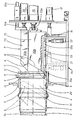
- 16 denotes a device by means of which to fit seals 6 automatically into the seating grooves 14 afforded by the sockets 3 of thermoplastic pipes 4.
- Such a device 16 essentially comprises: -a straight tubular element 1 offered immediately adjacent to and in alignment with the socket 3 of a pipe 4 and serving to support a seal 6 of external diameter greater than the internal diameter of the socket 3; -a plunger 7 capable of sliding movement within both the tubular element 1 and the socket 3, by which a seal 6 supported in the tubular element 1 is inserted into the seating groove 14; -means 10 by which to actuate the plunger 7 automatically.
- the tubular element 1 affords an internal cavity 2 with a cylindrical wall 20 of diameter identical to that of the socket 3, which in addition to its two open ends 5 is also accessible through a peripheral slot 11 of which the two edges 12 are designed to support a single seal 6 standing upright in a plane transverse to the axis 3a of the socket and resting on the internal wall 20 of the cavity 2 at bottom.
- the forwardmost end 8 of the plunger 7 directed toward the tubular element 1 presents an angled frontal surface 9; moreover, the cross section of the forwardmost end 8 is shaped in such a way as to interfere geometrically with a seal 6 occupying the slot 11 of the tubular element.
- the forwardmost end 8 of the plunger 7 is cylindrical and exhibits an external diameter identical to the diameter of the cavity 2, such that on insertion of the plunger 7 into the cavity, this same cylindrical end 8 will physically encounter a seal 6 currently occupying the slot 11.
- the plunger 7, actuated by automatic means 10 as aforementioned, reciprocates along a rectilinear trajectory coinciding substantially with the axis of alignment 3a between the tubular element 1 and the socket 3.
- such automatic actuator means 10 might be embodied simply as pneumatic cylinders, operated in conjunction with parallel guide rods 10a by which any unwarranted angular movement of the plunger 7 is prevented.
- the plunger 7 In a first stage of its forward stroke, the plunger 7 is moved away from the initial position toward the tubular element 1, and enters the cavity 2. On covering a short distance internally of the cavity 2, the angled surface 9 will impinge on the seal 6 and force it gradually forward until fully inside the cavity 2; needless to say, the seal 6 must necessarily assume an angled position in order to enable its insertion into the cavity 2, given its greater diametral dimensions. Thereafter, with the plunger 7 continuing to advance, the seal 6 is forced further to the point where its leading edge encounters the profile of the seating groove 14 afforded by the socket 3.
- the plunger 7 comprises a lever 13, accommodated internally of a longitudinal chase 15 formed in the surface of the plunger and extending back from the farthest extremity of the forwardmost end 8, which is anchored to the plunger 7 itself in such a manner as to permit both of rotation about a pivot 21 and of sliding longitudinally in relation to the plunger 7.
- the lever 13 is embodied with one end 13a formed as a seating element, and with its remaining end 13b connected to means 17 by which the lever itself is actuated prior to actuation of the plunger 7 as a whole.
- These further actuator means 17 enable the lever 13 both to pivot and to traverse in relation to the plunger 7 in such a way as to engage the seal 6 during the traverse movement and carry it forward by the leading edge through the tubular element 1, and by pivoting thereafter, to press the leading edge into the groove 14 in readiness for the full seating action performed by the plunger 7. It will be clear enough that the adoption of the lever 13 provides added positioning stability when locating the leading edge of the seal 6 in the groove 14 during this initial port of the seating operation.
- the plunger 7 can be embodied to advantage in a plurality of separable component section, and in the particular example of fig 1, in two sections 7S and 7I which combine to exhibit the same external geometry as that of a one-piece plunger 7, but are slidable in relation to one another along a plane disposed parallel to the trajectory of the plunger 7.
- the component sections 7S and 7I can therefore be actuated independently in such a way as to perform all the functions of the plunger 7 described thus far, while requiring a minimum of axial clearance internally of the socket 3.
- the two component sections 7S and 7I will be operated independently by the automatic actuator means 10, in such a way that the section 7S farthest removed from the lever 13 can be made to continue forward after movement of the other section 7I has already ceased.
Landscapes
- Engineering & Computer Science (AREA)
- Mechanical Engineering (AREA)
- Shaping Of Tube Ends By Bending Or Straightening (AREA)
- Lining Or Joining Of Plastics Or The Like (AREA)
- Sealing Material Composition (AREA)
- Automatic Assembly (AREA)
- Joints With Sleeves (AREA)
Applications Claiming Priority (2)
| Application Number | Priority Date | Filing Date | Title |
|---|---|---|---|
| IT362889 | 1989-09-22 | ||
| IT8903628A IT1235603B (it) | 1989-09-22 | 1989-09-22 | Dispositivo per l'introduziione automatica di guarnizioni in sedi scanalate di bicchieri di tubi termoplastici |
Publications (3)
| Publication Number | Publication Date |
|---|---|
| EP0419427A2 true EP0419427A2 (de) | 1991-03-27 |
| EP0419427A3 EP0419427A3 (en) | 1991-10-23 |
| EP0419427B1 EP0419427B1 (de) | 1994-07-27 |
Family
ID=11110872
Family Applications (1)
| Application Number | Title | Priority Date | Filing Date |
|---|---|---|---|
| EP90830414A Expired - Lifetime EP0419427B1 (de) | 1989-09-22 | 1990-09-21 | Vorrichtung zum automatischen Einsetzen von Dichtungsringen in die Nuten von thermoplastischen Rohrmuffen |
Country Status (6)
| Country | Link |
|---|---|
| US (1) | US5083354A (de) |
| EP (1) | EP0419427B1 (de) |
| JP (1) | JPH03208527A (de) |
| AT (1) | ATE109053T1 (de) |
| DE (1) | DE69011025T2 (de) |
| IT (1) | IT1235603B (de) |
Cited By (1)
| Publication number | Priority date | Publication date | Assignee | Title |
|---|---|---|---|---|
| FR2874344A1 (fr) * | 2004-08-17 | 2006-02-24 | Cms Automatisme Sarl | Procede pour placer la levre d'un joint circulaire dans une gorge circulaire |
Families Citing this family (6)
| Publication number | Priority date | Publication date | Assignee | Title |
|---|---|---|---|---|
| US6656582B2 (en) * | 2000-06-16 | 2003-12-02 | Tokai Rubber Industries, Ltd. | Rubber product with metallic structure and method of producing the same |
| IT1402619B1 (it) * | 2010-10-22 | 2013-09-13 | Ipm S R L | Sistema di inserimento guarnizione nel giunto a bicchiere di un tubo in materia plastica e contemporaneo controllo del suo posizionamento. |
| CN105290760A (zh) * | 2015-11-30 | 2016-02-03 | 中国北车集团大同电力机车有限责任公司 | 一种铁路机车悬挂臂压装装置 |
| DE102016104835B4 (de) * | 2016-03-16 | 2017-11-02 | Norma Germany Gmbh | Verfahren zum Einsetzen eines O-Ringes in einen Steckverbinder und Montagewerkzeug hierzu |
| JP6598895B2 (ja) * | 2018-02-13 | 2019-10-30 | 本田技研工業株式会社 | 可撓性リング嵌め込み装置 |
| CN115431217A (zh) * | 2022-10-17 | 2022-12-06 | 苏州伽利略智能自动化科技有限公司 | 内装式密封圈全自动安装装置及方法 |
Family Cites Families (7)
| Publication number | Priority date | Publication date | Assignee | Title |
|---|---|---|---|---|
| NL275549A (de) * | 1900-01-01 | |||
| US3553817A (en) * | 1968-04-10 | 1971-01-12 | Stanley M Lallak | Tool for installing resilient seals |
| CA999723A (en) * | 1973-04-27 | 1976-11-16 | Harald Eschholz | Apparatus for application of resilient seals |
| DE3336188A1 (de) * | 1983-10-05 | 1985-04-25 | Gebr. Ostendorf oHG, 2848 Vechta | Vorrichtung fuer das einsetzen eines mit einem stuetzring ausgeruesteten elastischen dichtringes in eine nut |
| GB2185294B (en) * | 1986-01-14 | 1988-08-24 | Taylor Clive Neal | O-ring insertion apparatus |
| DE3710829C2 (de) * | 1986-04-03 | 1993-12-02 | Coelestin Dipl Ing Ohrmann | Vorrichtung zum Einbringen von flexiblen Ringen, insbesondere Dichtungsringen |
| DE8710858U1 (de) * | 1987-07-13 | 1987-10-01 | Mertens, Peter, Dipl.-Ing. M.Sc. | O-Ring-Montagegreifer für Industrieroboter |
-
1989
- 1989-09-22 IT IT8903628A patent/IT1235603B/it active
-
1990
- 1990-09-19 US US07/585,300 patent/US5083354A/en not_active Expired - Fee Related
- 1990-09-21 AT AT90830414T patent/ATE109053T1/de not_active IP Right Cessation
- 1990-09-21 DE DE69011025T patent/DE69011025T2/de not_active Expired - Fee Related
- 1990-09-21 EP EP90830414A patent/EP0419427B1/de not_active Expired - Lifetime
- 1990-09-21 JP JP2250444A patent/JPH03208527A/ja active Pending
Cited By (1)
| Publication number | Priority date | Publication date | Assignee | Title |
|---|---|---|---|---|
| FR2874344A1 (fr) * | 2004-08-17 | 2006-02-24 | Cms Automatisme Sarl | Procede pour placer la levre d'un joint circulaire dans une gorge circulaire |
Also Published As
| Publication number | Publication date |
|---|---|
| JPH03208527A (ja) | 1991-09-11 |
| EP0419427A3 (en) | 1991-10-23 |
| IT8903628A0 (it) | 1989-09-22 |
| DE69011025T2 (de) | 1995-03-16 |
| EP0419427B1 (de) | 1994-07-27 |
| IT1235603B (it) | 1992-09-11 |
| DE69011025D1 (de) | 1994-09-01 |
| ATE109053T1 (de) | 1994-08-15 |
| US5083354A (en) | 1992-01-28 |
Similar Documents
| Publication | Publication Date | Title |
|---|---|---|
| CN105555207B (zh) | 一种外科夹具施夹器 | |
| US20210220928A1 (en) | Tool Head | |
| EP1171240B2 (de) | Pipettenspitze, pipettiervorrichtung und kombination aus pipettenspitze und pipettiervorrichtung | |
| EP1464283B1 (de) | Blutentnahmeeinrichtung mit einstellbarer Endkappe | |
| US8932304B2 (en) | Vascular graft | |
| EP0419427A2 (de) | Vorrichtung zum automatischen Einsetzen von Dichtungsringen in die Nuten von thermoplastischen Rohrmuffen | |
| CN105078533A (zh) | 手术仪器 | |
| EP3597357A1 (de) | Vorrichtung zum setzen von blindnietmuttern | |
| US5022421A (en) | Fluid connection method and assembly | |
| AU6561894A (en) | Screwdriver with replaceable bit assembly | |
| EP3476337A1 (de) | Verbindung zwischen drehgelenk und knöchel | |
| WO2008058704A1 (de) | Medizinische pumpe | |
| EP1557222A2 (de) | Pipettiervorrichtung mit einer Abwurfeinrichtung für Pipettenspitzen | |
| JPH1126137A (ja) | 端子アプリケータ | |
| EP0160559A1 (de) | Rohrverbindung | |
| US5100023A (en) | Rivet delivery device | |
| CA2448157A1 (en) | Assembly tool system and fixture | |
| CN101883660B (zh) | 机械的进给机构 | |
| KR101741250B1 (ko) | 누름자조절수단이 구비된 가스주입호스 및 이를 이용한 매니폴드게이지세트 | |
| DE3506967A1 (de) | Blindnietsetzwerkzeug | |
| CA2394461C (en) | Press and delivery system for a press | |
| US3967357A (en) | Wire skinning and wrapping tool | |
| NZ211853A (en) | Ear tag applicator with curved trocar | |
| WO2024215998A1 (en) | Pinch valve with convenient clamping mechanism | |
| JPS637475Y2 (de) |
Legal Events
| Date | Code | Title | Description |
|---|---|---|---|
| PUAI | Public reference made under article 153(3) epc to a published international application that has entered the european phase |
Free format text: ORIGINAL CODE: 0009012 |
|
| AK | Designated contracting states |
Kind code of ref document: A2 Designated state(s): AT DE DK ES FR GB GR NL SE |
|
| PUAL | Search report despatched |
Free format text: ORIGINAL CODE: 0009013 |
|
| AK | Designated contracting states |
Kind code of ref document: A3 Designated state(s): AT DE DK ES FR GB GR NL SE |
|
| 17P | Request for examination filed |
Effective date: 19920403 |
|
| 17Q | First examination report despatched |
Effective date: 19930510 |
|
| GRAA | (expected) grant |
Free format text: ORIGINAL CODE: 0009210 |
|
| AK | Designated contracting states |
Kind code of ref document: B1 Designated state(s): AT DE DK ES FR GB GR NL SE |
|
| PG25 | Lapsed in a contracting state [announced via postgrant information from national office to epo] |
Ref country code: GR Free format text: LAPSE BECAUSE OF FAILURE TO SUBMIT A TRANSLATION OF THE DESCRIPTION OR TO PAY THE FEE WITHIN THE PRESCRIBED TIME-LIMIT Effective date: 19940727 Ref country code: ES Free format text: THE PATENT HAS BEEN ANNULLED BY A DECISION OF A NATIONAL AUTHORITY Effective date: 19940727 Ref country code: DK Effective date: 19940727 |
|
| REF | Corresponds to: |
Ref document number: 109053 Country of ref document: AT Date of ref document: 19940815 Kind code of ref document: T |
|
| REF | Corresponds to: |
Ref document number: 69011025 Country of ref document: DE Date of ref document: 19940901 |
|
| PGFP | Annual fee paid to national office [announced via postgrant information from national office to epo] |
Ref country code: GB Payment date: 19940913 Year of fee payment: 5 |
|
| PGFP | Annual fee paid to national office [announced via postgrant information from national office to epo] |
Ref country code: NL Payment date: 19940930 Year of fee payment: 5 |
|
| PG25 | Lapsed in a contracting state [announced via postgrant information from national office to epo] |
Ref country code: SE Effective date: 19941027 |
|
| ET | Fr: translation filed | ||
| PLBE | No opposition filed within time limit |
Free format text: ORIGINAL CODE: 0009261 |
|
| STAA | Information on the status of an ep patent application or granted ep patent |
Free format text: STATUS: NO OPPOSITION FILED WITHIN TIME LIMIT |
|
| 26N | No opposition filed | ||
| PGFP | Annual fee paid to national office [announced via postgrant information from national office to epo] |
Ref country code: FR Payment date: 19950911 Year of fee payment: 6 |
|
| PGFP | Annual fee paid to national office [announced via postgrant information from national office to epo] |
Ref country code: AT Payment date: 19950914 Year of fee payment: 6 |
|
| PG25 | Lapsed in a contracting state [announced via postgrant information from national office to epo] |
Ref country code: GB Effective date: 19950921 |
|
| PGFP | Annual fee paid to national office [announced via postgrant information from national office to epo] |
Ref country code: DE Payment date: 19950928 Year of fee payment: 6 |
|
| PG25 | Lapsed in a contracting state [announced via postgrant information from national office to epo] |
Ref country code: NL Effective date: 19960401 |
|
| GBPC | Gb: european patent ceased through non-payment of renewal fee |
Effective date: 19950921 |
|
| NLV4 | Nl: lapsed or anulled due to non-payment of the annual fee |
Effective date: 19960401 |
|
| PG25 | Lapsed in a contracting state [announced via postgrant information from national office to epo] |
Ref country code: AT Effective date: 19960921 |
|
| PG25 | Lapsed in a contracting state [announced via postgrant information from national office to epo] |
Ref country code: FR Effective date: 19960930 |
|
| PG25 | Lapsed in a contracting state [announced via postgrant information from national office to epo] |
Ref country code: DE Effective date: 19970603 |
|
| REG | Reference to a national code |
Ref country code: FR Ref legal event code: ST |
|
| REG | Reference to a national code |
Ref country code: FR Ref legal event code: ST |