EP0419448A2 - Dispositif de purification de l'air dans des espaces individuels - Google Patents
Dispositif de purification de l'air dans des espaces individuels Download PDFInfo
- Publication number
- EP0419448A2 EP0419448A2 EP90890264A EP90890264A EP0419448A2 EP 0419448 A2 EP0419448 A2 EP 0419448A2 EP 90890264 A EP90890264 A EP 90890264A EP 90890264 A EP90890264 A EP 90890264A EP 0419448 A2 EP0419448 A2 EP 0419448A2
- Authority
- EP
- European Patent Office
- Prior art keywords
- air
- connection
- flow
- filter
- flow channel
- Prior art date
- Legal status (The legal status is an assumption and is not a legal conclusion. Google has not performed a legal analysis and makes no representation as to the accuracy of the status listed.)
- Withdrawn
Links
Images
Classifications
-
- F—MECHANICAL ENGINEERING; LIGHTING; HEATING; WEAPONS; BLASTING
- F24—HEATING; RANGES; VENTILATING
- F24F—AIR-CONDITIONING; AIR-HUMIDIFICATION; VENTILATION; USE OF AIR CURRENTS FOR SCREENING
- F24F8/00—Treatment, e.g. purification, of air supplied to human living or working spaces otherwise than by heating, cooling, humidifying or drying
- F24F8/10—Treatment, e.g. purification, of air supplied to human living or working spaces otherwise than by heating, cooling, humidifying or drying by separation, e.g. by filtering
- F24F8/117—Treatment, e.g. purification, of air supplied to human living or working spaces otherwise than by heating, cooling, humidifying or drying by separation, e.g. by filtering using wet filtering
- F24F8/125—Treatment, e.g. purification, of air supplied to human living or working spaces otherwise than by heating, cooling, humidifying or drying by separation, e.g. by filtering using wet filtering using wet filter elements
-
- F—MECHANICAL ENGINEERING; LIGHTING; HEATING; WEAPONS; BLASTING
- F24—HEATING; RANGES; VENTILATING
- F24F—AIR-CONDITIONING; AIR-HUMIDIFICATION; VENTILATION; USE OF AIR CURRENTS FOR SCREENING
- F24F11/00—Control or safety arrangements
- F24F11/70—Control systems characterised by their outputs; Constructional details thereof
- F24F11/72—Control systems characterised by their outputs; Constructional details thereof for controlling the supply of treated air, e.g. its pressure
- F24F11/74—Control systems characterised by their outputs; Constructional details thereof for controlling the supply of treated air, e.g. its pressure for controlling air flow rate or air velocity
-
- F—MECHANICAL ENGINEERING; LIGHTING; HEATING; WEAPONS; BLASTING
- F24—HEATING; RANGES; VENTILATING
- F24F—AIR-CONDITIONING; AIR-HUMIDIFICATION; VENTILATION; USE OF AIR CURRENTS FOR SCREENING
- F24F8/00—Treatment, e.g. purification, of air supplied to human living or working spaces otherwise than by heating, cooling, humidifying or drying
- F24F8/10—Treatment, e.g. purification, of air supplied to human living or working spaces otherwise than by heating, cooling, humidifying or drying by separation, e.g. by filtering
Definitions
- the invention relates to a device for cleaning the air from individual rooms, consisting of a housing which forms a flow channel with a fan and a filter device from a series connection of a coarse filter, an electrostatic filter and a carbon filter between two circulating air connections.
- Another way to keep the pollution and odor pollution of the air low in individual rooms is to convey the room air with the help of a circulating air blower through a filter device that contains a series connection of a coarse filter, an electrostatic filter and a carbon filter, so that dust, bacteria , Viruses, aerosols, odorants and. Like. Be filtered out effectively from the circulating air flow.
- the invention is therefore based on the object of providing a simply constructed device which allows air routing which is adapted to the respective conditions of an individual room and which ensures good air quality, with a comparatively low energy requirement for space heating or cooling.
- the invention achieves the object in that the flow channel has, at least on one side of the filter device, a device for dividing the flow between the associated circulating air connection and an external line connection.
- the air cleaning ensured by the filter device can also be used advantageously taking into account the respective fresh air requirement will.
- the external line connection is provided in the area of the exhaust air connection on the exhaust air side, i.e. in the flow direction upstream of the filter device, the size of the fresh air portion of the supply air intended for the room can be preselected via the device for flow distribution, the fresh air together with the exhaust air forming the recirculated air the room is subjected to appropriate cleaning.
- the excess pressure that builds up in the room determines the amount of air escaping from the room with such air guidance air, for which corresponding check valves or the like can be provided in a manner known per se.
- the heating or cooling of the supply air inevitably also detects the fresh air portion.
- the external line connection must be arranged downstream of the filter device, i.e. in the area of the supply air-side air connection of the housing, which means that part of the exhaust air sucked in from the room after it has been cleaned is blown out into the filter device as exhaust air in accordance with the flow distribution set.
- the negative pressure that arises in the room ensures an adapted supply of fresh air through existing room openings, which can again be equipped with a non-return flap.
- the device for flow distribution can be set manually.
- the device for flow distribution is adjusted by means of a control device as a function of at least one air parameter, preferably the temperature, which can be detected by a flow channel sensor, because in this case changes in the monitored air parameter can be taken into account immediately and automatically.
- the control of the flow distribution which is dependent on the air temperature, has the main effect of reducing the energy requirement, which is a priority in many applications.
- the flow mungskanalnetler monitors the exhaust air from the room and thus the room air with respect to the detected air parameter, and that unaffected by outside air, which is particularly important when fresh air supply via the external line connection.
- a further sensor for the parameter to be monitored can be arranged downstream of the external line connection in the flow direction in order to detect the influence of the fresh air supply on the parameter to be monitored.
- the device for flow distribution forms a structural unit which can be connected to the housing on the inlet or outlet side and which is attached to the housing on the exhaust air side or the air supply side as required.
- an additional blower with a controllable fresh air connection can be connected to the circulating air connection of the device for flow distribution provided on the outlet side, via which then the fresh air supply can also be finely regulated.
- the additional fan with the controllable fresh air connection forms a structural unit with an air heating or cooling device, so that the supply air for the room can be heated or cooled again as required.
- the training as a separate unit has the advantage that the basic unit for exhaust air control is modular can be expanded by a fresh air control.
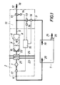
- the device for cleaning the air of an individual room 1 consists essentially of a dash-dot housing 2, which forms a flow channel 5 with a filter device 6 and a blower 7 between two recirculating air connections 3 and 4, so that the ambient air is sucked in via the recirculating air connection 3 on the exhaust air side, can be cleaned in the filter device 6 and can be blown into the individual room 1 again in a circulating air circuit via the supply air-side air connection 4.
- the filter device 6 has a series connection of a coarse filter 8, an electrostatic filter 9 and a carbon filter 10, which filters ensure adequate air purification.
- the flow channel 5 is provided, at least on one side of the filter device 6, with a device 11 for dividing the flow between the circulating air connection 3 or 4 and an external line connection 12.
- This device 11 consists, for example, of a control flap 13, which is assigned to the external line connection 12 and the associated recirculation connection 3 or 4, and which is actuated by an actuator 14 by a control device 15 as a function of an air parameter can be adjusted, which is detected via at least one flow channel sensor 16.
- the flow channel sensor 16 is preferably arranged in the flow direction in front of the external line connection 12.
- a flow channel sensor 17 can also be arranged downstream of the outer line connection 12 in the flow direction in order to be able to detect the influence of the outer line connection 12 on the supply air, as shown in FIG the filter device 6 is arranged.
- the supply of fresh air 18 can thus be controlled via this outer line connection 12, for example depending on the temperature of the exhaust air 19 of the room 1.
- the flow channel sensor 16 is in this case designed as a temperature sensor.
- the temperature of the supply air 20 flowing into the room is monitored via the flow channel sensor 17, which allows a sensitive regulation of the fresh air supply as a function of the respective temperature conditions.
- the circulating air conveyed through the filter device 6 with the admixed fresh air 18 can be heated or cooled as required via an air heating device 21 or a cooling device 22.
- the heating and cooling device can be constructed very differently.
- heat exchangers are provided in the housing 2, which has corresponding connecting lines 23 and 24 for the heat transfer medium and the refrigerant.
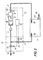
- the device 11 for flow distribution in the region of the supply air-side air connection 4 is provided according to FIG. 2.
- the exhaust air 25 can thus be controlled via the external line connection 12 in accordance with an air parameter to be monitored, which is formed, for example, by a pollutant, so that the exhaust air rate can be increased accordingly if the proportion of pollutants is increased.
- the flow channel sensor provided for determining the proportion of pollutants must be provided in the flow direction upstream of the filter device 6.
- the outer line connection 12 is arranged downstream of the filter device 6 in the area of the inlet-side circulating air connection 4, the exhaust air is cleaned and consequently does not represent any environmental pollution.
- the reduced amount of supply air 20 due to the blowing off of the exhaust air 25 compared to the exhaust air 19 results a negative pressure in room 1, which in turn ensures fresh air 18 is sucked in via a non-return valve 27.
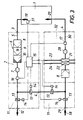
- an additional blower 28 with a fresh air connection 29 can be connected to the device on FIG. Since this fresh air connection 29 again connects to the supply air line 30 via a device 11 for flow distribution, the ratio of the fresh air 18 to the recirculated air can be preselected via the control flaps 13 of this device 11, the actuators 14 of the control flaps 13 corresponding to a predetermined program via the control device 15 can be applied.
- the setpoint of the air parameter to be monitored, for example the temperature can be specified via a setpoint input 31 of the control device 15, which is preferably designed as a computer.
- any additional devices provided such as a coarse filter 8, a heating device 21 or a cooling device 22 u.
- the device 11 for dividing the flow between a circulating air connection and an external line connection can form a further structural unit in order to provide the individual devices with such devices and to add them in a modular manner depending on the requirements.
Landscapes
- Engineering & Computer Science (AREA)
- Chemical & Material Sciences (AREA)
- Combustion & Propulsion (AREA)
- Mechanical Engineering (AREA)
- General Engineering & Computer Science (AREA)
- Physics & Mathematics (AREA)
- Fluid Mechanics (AREA)
- Electrostatic Separation (AREA)
- Ventilation (AREA)
Applications Claiming Priority (2)
| Application Number | Priority Date | Filing Date | Title |
|---|---|---|---|
| AT2178/89A AT393092B (de) | 1989-09-19 | 1989-09-19 | Vorrichtung zum reinigen der luft von einzelraeumen |
| AT2178/89 | 1989-09-19 |
Publications (2)
| Publication Number | Publication Date |
|---|---|
| EP0419448A2 true EP0419448A2 (fr) | 1991-03-27 |
| EP0419448A3 EP0419448A3 (en) | 1992-05-06 |
Family
ID=3529384
Family Applications (1)
| Application Number | Title | Priority Date | Filing Date |
|---|---|---|---|
| EP19900890264 Withdrawn EP0419448A3 (en) | 1989-09-19 | 1990-09-18 | Apparatus for purifying the air of individual rooms |
Country Status (2)
| Country | Link |
|---|---|
| EP (1) | EP0419448A3 (fr) |
| AT (1) | AT393092B (fr) |
Cited By (1)
| Publication number | Priority date | Publication date | Assignee | Title |
|---|---|---|---|---|
| CN111426015A (zh) * | 2020-04-29 | 2020-07-17 | 珠海格力电器股份有限公司 | 空调机组健康度监测方法、装置及空调机组 |
Families Citing this family (1)
| Publication number | Priority date | Publication date | Assignee | Title |
|---|---|---|---|---|
| DE102019107183B4 (de) * | 2019-03-20 | 2021-11-04 | Novus air GmbH | Ventilatorenanordnung und Entstaubungsanlage |
Family Cites Families (11)
| Publication number | Priority date | Publication date | Assignee | Title |
|---|---|---|---|---|
| JPS533345B2 (fr) * | 1971-11-16 | 1978-02-06 | ||
| DE2244608B2 (de) * | 1972-09-05 | 1976-03-18 | Gebrüder Sulzer AG, Winterthur (Schweiz) | Anlage zur individuellen klimatisierung der einzelnen raeume eines gebaeudes |
| US3956458A (en) * | 1973-11-16 | 1976-05-11 | Paul Brent Anderson | Method and apparatus for air purification |
| DE2412588A1 (de) * | 1974-03-15 | 1975-09-18 | Mulfingen Elektrobau Ebm | Dunstabzugshaube |
| DE2725457C2 (de) * | 1977-06-04 | 1983-12-15 | Johnson Service Co., Milwaukee, Wis. | Verfahren zum Regeln der Luftzufuhr in belüfteten Räumen und Vorrichtung zur Durchführung des Verfahrens |
| JPS5960141A (ja) * | 1982-09-28 | 1984-04-06 | Toupure Kk | 空気調和装置 |
| DE3439288A1 (de) * | 1983-10-28 | 1985-05-09 | Siemens AG, 1000 Berlin und 8000 München | Verfahren zur optimierung des energieverbrauchs einer luftaufbereitungsanlage fuer raumklimatisierung |
| DE3509621C2 (de) * | 1985-03-16 | 1987-01-08 | Turbon-Tunzini Klimatechnik GmbH, 5060 Bergisch Gladbach | Raumlufttechnische Anlage mit einem Zweikanalsystem |
| DE3623731A1 (de) * | 1986-07-14 | 1988-01-21 | Hellmut Hinkel | Luftreiniger |
| FI78979C (fi) * | 1988-02-18 | 1989-10-10 | Halton Oy | Foerfarande foer reglering av luftkonditionering och luftkonditioneringsanordning foer anvaendning vid foerfarandet. |
| CH675294A5 (fr) * | 1989-02-20 | 1990-09-14 | Felix Kalberer |
-
1989
- 1989-09-19 AT AT2178/89A patent/AT393092B/de not_active IP Right Cessation
-
1990
- 1990-09-18 EP EP19900890264 patent/EP0419448A3/de not_active Withdrawn
Cited By (1)
| Publication number | Priority date | Publication date | Assignee | Title |
|---|---|---|---|---|
| CN111426015A (zh) * | 2020-04-29 | 2020-07-17 | 珠海格力电器股份有限公司 | 空调机组健康度监测方法、装置及空调机组 |
Also Published As
| Publication number | Publication date |
|---|---|
| ATA217889A (de) | 1990-06-15 |
| EP0419448A3 (en) | 1992-05-06 |
| AT393092B (de) | 1991-08-12 |
Similar Documents
| Publication | Publication Date | Title |
|---|---|---|
| DE1679480A1 (de) | Steuer-Vorrichtung fuer Klima-Anlagen | |
| DE69405041T2 (de) | Verfahren und Vorrichtung zur Regelung der Luftgeschwindigkeit eines Rauchabzuges mit variabelen Ausweichleitungswiderstand | |
| DE2149548B2 (de) | Klimaanlage für Eisenbahnfahrzeuge | |
| DE19847504C1 (de) | Verfahren zur Steuerung der Luftvolumenströme in einer raumlufttechnischen Anlage | |
| DE2455585C3 (de) | Verfahren zum Abkühlen von heifieminsbesondere staubbeladenem-Rauchgas in einem Wärmeaustauscher und Vorrichtung zum Durchführen des Verfahrens | |
| DE102016105305A1 (de) | Innenraumlüftungsanlage | |
| EP0294730B1 (fr) | Dispositif aéraulique | |
| DE3509621C2 (de) | Raumlufttechnische Anlage mit einem Zweikanalsystem | |
| AT393092B (de) | Vorrichtung zum reinigen der luft von einzelraeumen | |
| DE2248284A1 (de) | Schaltungsanordnung | |
| EP0385395A2 (fr) | Dispositif de commande pour les lamelles d'un appareil de chauffage d'air, de refroidissement d'air ou d'aération | |
| DE10036502C1 (de) | Klimaanlage für ein Fahrzeug | |
| DE2625534B2 (de) | Vorrichtung zur Aufbereitung von Zuluft für Räume | |
| DE2548494C3 (de) | Anlage zur Regelung der Temperatur und des Stromungsgleichgewichtes in einem Raum | |
| DE1931155B2 (de) | Gerät zum Zuführen von Luft in einem Raum | |
| EP0003970B1 (fr) | Procédé de ventilation de pièces et dispositif de ventilation pour la mise en oeuvre du procédé | |
| DE2634713B2 (de) | Verfahren und Vorrichtung zum Beheizen und Belüften des Innenraums von Omnibussen | |
| EP0384884A2 (fr) | Installation d'aération | |
| DE2212356C3 (de) | Anlage für die unabhängige Temperierung einer Vielzahl von Räumen | |
| CH648922A5 (en) | Device for air-conditioning a number of rooms | |
| DE2324262A1 (de) | Klimaanlage | |
| DE29614928U1 (de) | Belüftungsanlage für einen Stall | |
| DE102016211200A1 (de) | Lüftungsgerät mit schwenkbarem Filter | |
| DE2166287B2 (de) | Luftansaugkanal- und Abgaskanaleinheit für eine Gasbrenneranlage mit Fremdzug | |
| DE60302819T2 (de) | Luftbehandlungsvorrichtung und Verfahren zur Durchführung dieser Luftbehandlung |
Legal Events
| Date | Code | Title | Description |
|---|---|---|---|
| PUAI | Public reference made under article 153(3) epc to a published international application that has entered the european phase |
Free format text: ORIGINAL CODE: 0009012 |
|
| AK | Designated contracting states |
Kind code of ref document: A2 Designated state(s): AT BE CH DE FR GB IT LI NL SE |
|
| PUAL | Search report despatched |
Free format text: ORIGINAL CODE: 0009013 |
|
| AK | Designated contracting states |
Kind code of ref document: A3 Designated state(s): AT BE CH DE FR GB IT LI NL SE |
|
| STAA | Information on the status of an ep patent application or granted ep patent |
Free format text: STATUS: THE APPLICATION IS DEEMED TO BE WITHDRAWN |
|
| 18D | Application deemed to be withdrawn |
Effective date: 19921109 |