EP0419756A2 - Transformateur imprimé - Google Patents
Transformateur imprimé Download PDFInfo
- Publication number
- EP0419756A2 EP0419756A2 EP90103477A EP90103477A EP0419756A2 EP 0419756 A2 EP0419756 A2 EP 0419756A2 EP 90103477 A EP90103477 A EP 90103477A EP 90103477 A EP90103477 A EP 90103477A EP 0419756 A2 EP0419756 A2 EP 0419756A2
- Authority
- EP
- European Patent Office
- Prior art keywords
- printed circuit
- conductors
- conductor
- disposed
- transformer
- Prior art date
- Legal status (The legal status is an assumption and is not a legal conclusion. Google has not performed a legal analysis and makes no representation as to the accuracy of the status listed.)
- Withdrawn
Links
Images

Classifications
-
- H—ELECTRICITY
- H01—ELECTRIC ELEMENTS
- H01P—WAVEGUIDES; RESONATORS, LINES, OR OTHER DEVICES OF THE WAVEGUIDE TYPE
- H01P5/00—Coupling devices of the waveguide type
- H01P5/08—Coupling devices of the waveguide type for linking dissimilar lines or devices
- H01P5/10—Coupling devices of the waveguide type for linking dissimilar lines or devices for coupling balanced lines or devices with unbalanced lines or devices
-
- H—ELECTRICITY
- H05—ELECTRIC TECHNIQUES NOT OTHERWISE PROVIDED FOR
- H05K—PRINTED CIRCUITS; CASINGS OR CONSTRUCTIONAL DETAILS OF ELECTRIC APPARATUS; MANUFACTURE OF ASSEMBLAGES OF ELECTRICAL COMPONENTS
- H05K1/00—Printed circuits
- H05K1/16—Printed circuits incorporating printed electric components, e.g. printed resistors, capacitors or inductors
Definitions
- the present invention relates generally to ultrahigh frequency circuits, and more particularly to ultrahigh frequency circuits that are printed on a circuit board or ceramic substrate.
- the present invention relates to the fabrication of a transformer having windings printed on the circuit board or substrate.
- a rather critical stage in a conventional radio receiver is a radio frequency mixer that converts a selected radio frequency to a fixed intermediate frequency.
- the ability of the radio receiver to reject intermodulation interference is primarily a function of the performance of the radio frequency mixer.
- the mixer multiplies radio frequency signals by a local oscillator signal to produce corresponding intermediate frequency signals.
- the mixer also multiplies or "mixes" the radio frequency signals among themselves to obtain some level of interfering signal at the intermediate frequency.
- Balanced mixers use balanced signals which are fed through non-linear components and then combined to provide cancellation of certain undesired signals. In particular, it is possible to cancel the fundamental and odd-order intermodulation components.
- Balanced mixers typically require at least one balanced transformer.
- the balanced transformer typically includes windings on a toroidal ferrite core. The winding of such a transformer is therefore a relatively expensive operation. Also, the assembly of such a transformer onto a circuit board or substrate involves additional costs.
- the transformer leads are provided by the ends of the wires forming the transformer's windings which require hand insertion and soldering to the circuit board, with careful attention to dressing of the leads to maintain balance of the signals. The transformer is then secured to the circuit board by applying cement.
- the balanced transformer As part of the printed circuit itself, it would be desirable to manufacture the balanced transformer as part of the printed circuit itself.
- a transformer is formed as part of a printed circuit on a planar substrate of insulating material.
- the transformer has a center-tapped winding formed by a loop of a strip transmission line having first and second coextensive elongated conductors disposed on the substrate.
- the first and second conductors are disposed adjacent each other on respective opposite sides of the substrate.
- the second conductor is connected to a center tap, and at a second end portion of the strip transmission line, the first conductor is also connected to the center tap.
- the center tap is a ground plane provided by conductive regions disposed on the substrate.
- an unbalanced signal is fed into the transformer at a second winding including at least a third elongated conductor disposed on the substrate coextensive with the first and second conductors.
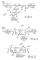
- FIG. 1 there is a shown a schematic diagram of the front end of a ultrahigh-frequency radio receiver generally designated 10 having a mixer circuit generally designated 11 incorporating a balanced transformer 12 in accordance with the present invention.
- the radio receiver 10 employs the conventional superheterodyne principle to use an intermediate-frequency (IF) amplifier 13 having a fixed intermediate frequency for amplifying a signal selected from a number of radio frequency signals received at an antenna 14.
- the desired radio frequency is selected by tuning the frequency of a local oscillator 15 to a frequency that is offset from the desired radio frequency by an amount equal to the fixed intermediate frequency.
- any non-linear circuit element such as a diode or a bipolar or field-effect transistor, can be used as a mixer because the non-linearity in the circuit element includes a "square-law" term causing multiplication between sinusoidal components of different frequencies to generate sum and difference frequencies.
- a mixer employing a single non-linear element has the disadvantage that product signals are also generated by the mixing or multiplying together of different radio frequency signals among themselves, as well as between the local oscillator signal and each of the radio frequency signals. It is known that this problem can be solved by using more than one non-linear element and arranging the non-linear elements in a balanced circuit.
- the balanced mixer is known as a "singly-balanced" mixer.
- the singly-balanced mixer also suppresses odd order intermodulation products of the radio frequency signals.
- the problem of intermodulation interference is particularly troublesome in a superheterodyne receiver. Since the intermodulation products occur at the intermediate frequency, the intermodulation interference cannot be eliminated by increasing the selectivity of the intermediate frequency amplifier. When it is desired to tune the superheterodyne receiver over a broad band of frequencies, or when it is desired to obtain the best possible performance from the receiver, the presence of intermodulation interference may become a limiting factor. In this case it may become necessary to use a balanced mixer.
- a balanced mixer can also be used to prevent radiation of the local oscillator signal from the antenna 14.
- a radio frequency amplifier 16 may also help to isolate the antenna 14 from the local oscillator 15, but the primary purpose of the radio frequency amplifier is to improve the noise figure of the receiver by providing gain to overcome conversion loss in the mixer and loss in tuned radio frequency circuits coupled between the antenna and the mixer. But the degree of isolation provided by the radio frequency amplifier 16 is limited by the desire to limit the gain of the radio frequency amplifier to no more than is need to provide a good noise figure for the radio receiver. Excessive gain in the radio frequency amplifier tends to increase the intermodulation interference because the intermodulation products generated in the mixer increase as the square or a higher order of the radio frequency signal level that is input to the mixer.
- a preferred form of singly-balanced mixer 11 is shown in FIG. 1.
- a pair of directional diodes 17, 18 function as an electronic switch that is alternately opened and closed at the local oscillator frequency. This electronic switch alternately shunts to ground an intermediate connection point 19 between the radio frequency amplifier 16 and the intermediate amplifier 13.
- the diodes 17 and 18 have a conductive state when current induced from the local oscillator 15 is flowing in a forward direction through the diodes, and a non-conductive state when the diodes 17 and 18 are reverse-biased by the signal from the local oscillator.
- the ability of the diodes 17 and 18 to function as an electronic switch is highly dependent upon the degree to which the transformer 12 is balanced.
- the degree to which the transformer 12 is balanced determines the degree to which the local oscillator signal is absent from the intermediate connection point 19.
- the transformer 12 should provide a low impedance connection between the intermediate point 19 and signal ground.
- the transformer 12 should be balanced with respect to ground in this fashion over a relatively wide range of frequencies.
- a transformer having these desired characteristics is known as a "balun" transformer.
- Such a transformer may convert an unbalanced signal from a terminal 20 to a balanced signal on terminals 21 and 22 such that the voltage on terminal 21 with respect to ground is substantially equal and opposite to the voltage on terminal 22 with respect to ground.
- such as transformer can be fabricated as a printed circuit in accordance with the present invention.
- the diodes 17 and 18 In order for the diodes 17 and 18 to function as a shunt switch between the radio frequency amplifier 16 and the intermediate frequency amplifier 13, it is necessary to provide an impedance between the radio frequency amplifier 16 and the intermediate connection point 19 that is relatively small in comparison to the impedance of the electronic switch when the electronic switch is closed.
- this impedance is provided by a capacitance C1.
- this coupling is provided by a lowpass filter including a series inductor L and a shunt capacitor C2. The values of the inductance L and the capacitance C2 are selected for resonance at approximately the intermediate frequency.
- the value of the capacitor C1 is desirable for the value of the capacitor C1 to be selected for resonance with the inductance L at approximately the radio frequency.
- the values of the capacitors C1 and C2 should be about 2 picofarads and 4 picofarads, respectively, and the inductor L should have a value of approximately 0.03 microhenries.
- radio frequency choke that shunts the intermediate point 19 to ground for lower frequencies and provides a DC return path for the diodes 17 and 18.
- the inductance of the radio frequency choke (RFC) should be about 10 to 20 times the inductance L.
- FIG. 2 there is shown a schematic diagram of a conventional doubly-balanced mixer circuit generally designated 30 which includes a balun transformer 31, a directional diode ring 32 including four directional diodes, and a balanced center-tapped transformer 33.
- an antenna 14′ and a radio frequency amplifier 16′ are connected to the primary of the balun transformer 31, a local oscillator 15′ connected to the center-tap of the transformer 33, and an intermediate frequency amplifier 13′ is connected to an output winding of the center-tapped transformer 33. Since the mixer 30 is doubly balanced, however, the connections and positions of the radio frequency amplifier 16′, local oscillator 15′ and intermediate frequency amplifier 13′ can be interchanged.
- the local oscillator frequency is chosen to be higher than the desired radio frequency, for example, it may be desirable to interchange the connections and positions of the antenna 14′ and the radio frequency amplifier 16′ with the local oscillator 15′ in order to reduce the required size of the transformer 31, since the required inductance or size of the transformer 31 is inversely proportional to the frequency of the signal to be coupled from its primary windings to its secondary windings.
- the radio frequency amplifier 16′ as well as the local oscillator 15′ are isolated from the intermediate frequency amplifier 13′. As will become apparent from the discussion below with respect to FIGs. 7-10, however, the isolation of the intermediate frequency amplifier 13′ from the local oscillator 15′ is limited by capacitive coupling between the windings of the transformer 33 and the relatively high level of the local oscillator signal applied to the center-tap of the transformer 33.
- FIG. 3 there is shown an alternative doubly-balanced mixer circuit generally designated 30′ that uses a pair of balun transformers 31′ and 33′ to prevent the problem of capacitive coupling that could occur for the circuit of FIG. 2.
- the alternative circuit includes a transformer or strip-line coupler 34 to inject the local oscillator signal across the diode bridge 32′.
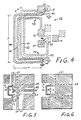
- the preferred transformer 12 includes printed metal patterns called "traces" on both the top and bottom surfaces of a substrate such as a substrate or circuit board (not shown).
- the tope and bottom traces are distinguished by different cross-hatching, and the bottom trace is shown in dashed outlines.
- the substrate thickness t is 1.6 mm
- the transformer length l is 10 mm
- the transformer width w is 5 mm
- the line widths of the transformer windings is 0.3 mm .
- the substrate (not shown), for example, is fire retardant fiber-glass circuit board known as "FR4", although multilayer ceramic or other insulating substrates could be used as alternatives.
- the windings of the balun transformer 12 include a pair of first and second co-extensive elongated conductors 41, 42 disposed on adjacent one another on opposite sides of the substrate (not shown) to form a strip transmission line being disposed in a loop and having first and second end portions 43, 44.
- the second conductor 42 has a connection 45 to a ground plane at the first end portion 43 of the strip transmission line, and the first conductor 41 has a connection 46 to the ground plane at the second end portion 44 of the strip transmission line.
- the first conductor 41 is provided with the terminal 21 at the first end portion of the strip transmission line, and the second conductor 42 is provided with the terminal 22 at the second end portion of the strip transmission line. Due to this construction, a balanced signal is provided from the terminals 21 and 22.
- the top printed circuit trace includes pads at the connections 21 and 19.
- the second diode 18 is preferably included in the same surface mount package as the first diode 17.
- the top trace of the printed circuit also has a mounting pad 47 that is connected to the terminal 22 by a conductive via 48 extending through the substrate (not shown).
- the balun transformer 12 preferably includes a third elongated conductor 49 disposed on the substrate (not shown) to be co-extensive with the first and second conductors 41, 42.
- the third conductor 49 forms a primary winding, while the first and second conductors 41, 42 together form a center-tapped secondary winding of the balun transformer 12.
- the primary winding preferably includes a fourth elongated conductor 50 connected in parallel with the third conductor 49 so that the third conductor 49 is adjacent to the first conductor 41 on one side of the substrate, and the fourth conductor 50 is adjacent the second conductor 42 on the other side of the substrate.
- the third and fourth elongated conductors for example, have end portions which are connected together by vias 51 and 52.
- additional vias not shown to interconnect the third and fourth conductors at intermediate locations along their lengths. These intermediate vias would ensure that the third and fourth conductors have equal potentials at the intermediate locations.
- FIGS. 5 and 6 there are shown the top and bottom traces of a printed circuit board 60 of the mixer 11 of FIG. 1 which incorporates the balun transformer of FIG. 4.
- FIG. 6 is a view of the bottom trace of the circuit board 60 of FIG. 5 as would be seen if one could look through the circuit board 60.
- the bottom trace is shown in this fashion to facilitate comparison of the adjacent and corresponding areas of the top and bottom traces.
- the major portion of the bottom trace is devoted to establishing a ground plane 61.
- the upper trace in FIG. 5 includes strip lines 62, 63 and 64 which are disposed above the ground plane 61 to provide 50 ohm transmission lines for the radio frequency, local oscillator, and intermediate frequency signals.
- Signal ground is also established on the top of the board by numerous regions of the upper trace which are connected to the ground plane 61 by vias such as the vias 65.
- the electrical components in the mixer 10 are shown in dashed representation in FIG. 5 and are mounted on the top of the circuit board 60.
- the diodes 17 and 18 are included in a surface mount package 66.
- the package 66 for example, is a Nippon Electric Corporation Part No. ND411G-1, or a Hitachi Part No. HSM88AS, UHF single balanced mixer silicon epitaxial Schottky barrier diode pair.
- FIG. 7 there is shown the top view of a circuit board generally designated 70 including the doubly-balanced mixer generally designated 30 of FIG. 2 which incorporates two printed circuit transformers in accordance with the present invention.
- the bottom trace of the printed circuit board 70 is shown in FIG. 8, as the bottom trace would appear if one could look through the circuit board.
- the only components mounted to the circuit board 70 are a pair of mixer diode packages 71 and 72, each including two directional diodes in the diode ring 32.
- the radio frequency (RF), local oscillator (LO), and intermediate frequency (IF) signals are conveyed on strip lines 73, 74 and 75, respectively.
- RF radio frequency
- LO local oscillator
- IF intermediate frequency
- the radio frequency strip line 73 is fairly well isolated from the local oscillator and intermediate frequency strip lines 74 and 75. This isolation could be enhanced by metal shields disposed along the line 76 and perpendicular to the circuit board 70. Due to the construction of the transformer 33, however, there is some unbalanced capacitive coupling between the local oscillator strip line 74 and the intermediate frequency strip line 75.
- FIGS. 9 and 10 there is shown a circuit board 70′ and the top and bottom traces for the doubly-balanced mixer circuit of FIG. 3.
- the transformer 33′ is a balun transformer, having its center tap connected to the ground plane formed by the top trace in FIG. 9.
- the local oscillator signal is applied to the diode ring 32′ by a strip line coupler 34 which provides inductive and capacitive coupling from the local oscillator strip line 74′ to a pair of balanced lines 80, 81 (FIG. 10) formed in the bottom trace.
- the local oscillator strip line 74′ is terminated in a symmetrical fashion at a connection to the ground plane on the top trace. Therefore there is a high degree of isolation between the local oscillator strip line 74′ and the intermediate frequency strip line 75′ along the plane 78.
- the strip line 74′ could be used as a quarter-wave resonator for the local oscillator (15 ⁇ in FIG. 3). In this case a rather high signal level would be achieved in the strip line 74′.
- the quarter-wave resonator could be capacitively loaded at its electrically open end with a varactor diode in the conventional fashion to provide electronic tuning of the resonator and adjustment of the frequency of the local oscillator for selecting a desired radio frequency.
- the printed circuit transformers are quite small even though they use "air" cores.
- ferrite cores could be provided by ferrite chips laid over the top and bottom traces of the transformer windings.
- slots could be provided in a substrate such as a circuit board to permit two pieces of a split ferrite core be joined that would completely encircle the loop of the transformer windings.
- the balanced mixer circuits have been shown to include pairs of two directional diodes or rings of four directional diodes, a series combination of diodes can be substituted for each of the diodes shown in the drawings in order to increase the dynamic range or "compression point" of the mixer.
- a resistor having a value of about 6 ohms or more, could be added in series with each of the diodes in the pair or ring, in order to increase the dynamic range or "compression point" of the mixer at the expense of about a 0.5 dB increase in conversion loss.
- the invention has been described above in terms of conductive elements arranged upon a circuit board or planar substrate consisting of a single planar portion of insulating material, the invention can just as readily be practiced with the conductive elements described above arranged about a planar portion of one or more insulating layers inside a multi-layer substrate.
- the Du Pont Co. for example, has introduced a ceramic "green tape" material system for fabricating a ceramic substrate having multiple layers formed with printed circuits between the layers. Each layer can be selected with a respective thickness within the range of about 0.025 mm (.001") to about 0.76 mm (0.030"), and up to 60 or more layers can be defined in a single substrate.
- one or more of the layers could include ferrite material to increase the inductive coupling of conductive elements disposed on or between such layers, or to extend the bandwidth of the conductive elements by selection of the ferrite material frequency characteristics.
- ferrite material By printing a central conductive ground plane, electromagnetically isolated circuits can be formed between layers on opposite sides of that ground plane.
- Some vias could be formed between the ground plane corresponding to the signal conductors between the plane 76 in FIGs. 7 and 8 or planes 77′ and 78 in FIGs. 9 and 10.
- Other vias could extend to the external surfaces of the multi-layer ceramic substrate for surface mounting of the directional diode packages. In special cases it should be possible to mount the directional diode packages between layers with holes in the outside layers for accessibility. Therefore it should be possible to form the doubly-balanced mixer circuit of FIG. 2 or FIG. 3 above in a package smaller than about 1.5 mm wide, 2.0 mm long, and 5.0 mm thick.
Landscapes
- Coils Or Transformers For Communication (AREA)
- Superheterodyne Receivers (AREA)
Applications Claiming Priority (2)
| Application Number | Priority Date | Filing Date | Title |
|---|---|---|---|
| US07/412,949 US5003622A (en) | 1989-09-26 | 1989-09-26 | Printed circuit transformer |
| US412949 | 1999-10-05 |
Publications (2)
| Publication Number | Publication Date |
|---|---|
| EP0419756A2 true EP0419756A2 (fr) | 1991-04-03 |
| EP0419756A3 EP0419756A3 (en) | 1991-09-11 |
Family
ID=23635136
Family Applications (1)
| Application Number | Title | Priority Date | Filing Date |
|---|---|---|---|
| EP19900103477 Withdrawn EP0419756A3 (en) | 1989-09-26 | 1990-02-22 | Printed circuit transformer |
Country Status (3)
| Country | Link |
|---|---|
| US (1) | US5003622A (fr) |
| EP (1) | EP0419756A3 (fr) |
| CA (1) | CA2008067A1 (fr) |
Cited By (7)
| Publication number | Priority date | Publication date | Assignee | Title |
|---|---|---|---|---|
| EP0539133A1 (fr) * | 1991-10-23 | 1993-04-28 | Nokia Mobile Phones Ltd. | Transformateur |
| EP0570125A1 (fr) * | 1992-05-08 | 1993-11-18 | Sony Corporation | Circuit de conversion dissymétrique-symétrique utilisé comme circuit d'entrée d'un mélangeur |
| US6018277A (en) * | 1997-03-20 | 2000-01-25 | Nokia Mobile Phones Limited | Series of strip lines for phasing and balancing a signal |
| DE19943955A1 (de) * | 1999-09-14 | 2001-04-12 | Bosch Gmbh Robert | Symmetrierglied |
| EP1076935A4 (fr) * | 1998-05-06 | 2002-08-28 | Northrop Grumman Corp | Melangeur hyperfrequence monolithique doublement symetrique a circuit integre |
| EP1758200A3 (fr) * | 2005-08-23 | 2007-03-07 | Synergy Microwave Corproation | Transformateur à changement de mode à plusieurs couches, mélangeurs et amplificateurs |
| EP1265358A3 (fr) * | 2001-05-25 | 2008-11-12 | Toko Kabushiki Kaisha | Composant électronique laminé |
Families Citing this family (43)
| Publication number | Priority date | Publication date | Assignee | Title |
|---|---|---|---|---|
| JPH0644693B2 (ja) * | 1989-01-10 | 1994-06-08 | 松下電器産業株式会社 | ミクサ回路 |
| US5280647A (en) * | 1990-06-14 | 1994-01-18 | Taisei Co., Ltd. | Double-balanced mixer with triple-layer film transformers |
| FI89990C (fi) * | 1991-12-19 | 1993-12-10 | Nokia Mobile Phones Ltd | Diodblandare |
| US5451914A (en) * | 1994-07-05 | 1995-09-19 | Motorola, Inc. | Multi-layer radio frequency transformer |
| US5801602A (en) * | 1996-04-30 | 1998-09-01 | 3Com Corporation | Isolation and signal filter transformer |
| US6097349A (en) * | 1997-11-18 | 2000-08-01 | Ericsson Inc. | Compact antenna feed circuits |
| US6252532B1 (en) | 1998-02-26 | 2001-06-26 | 3Com Corporation | Programmable compensation and frequency equalization for network systems |
| JP3675688B2 (ja) * | 2000-01-27 | 2005-07-27 | 寛治 大塚 | 配線基板及びその製造方法 |
| US6380821B1 (en) | 2000-08-24 | 2002-04-30 | International Business Machines Corporation | Substrate shielded multilayer balun transformer |
| US6483397B2 (en) * | 2000-11-27 | 2002-11-19 | Raytheon Company | Tandem six port 3:1 divider combiner |
| US6529090B2 (en) | 2001-05-15 | 2003-03-04 | Lockheed Martin Corporation | Two-sided printed circuit anti-symmetric balun |
| US6879192B2 (en) * | 2001-10-18 | 2005-04-12 | L-3 Communications Corporation | Even harmonic mixer with high-input, third-order intercept point |
| US6810241B1 (en) * | 2002-01-30 | 2004-10-26 | Northrop Grumman Corporation | Microwave diode mixer |
| US6765469B2 (en) | 2002-02-21 | 2004-07-20 | Eni Technology, Inc. | Printed circuit board transformer |
| EP1620714B1 (fr) * | 2003-04-15 | 2014-03-12 | Senseonics, Incorporated | Systeme et procede permettant d'attenuer l'effet d'une lumiere ambiante sur un capteur optique |
| US7020452B1 (en) * | 2003-04-29 | 2006-03-28 | Sirenza Microdevices, Inc. | Actively matched center-tapped marchand balanced mixer |
| US7283345B2 (en) * | 2003-07-14 | 2007-10-16 | Gang Liu | PCB trace coupling system for providing high voltage isolation |
| US7263343B2 (en) * | 2003-08-20 | 2007-08-28 | Sharp Kabushiki Kaisha | Frequency converter and radio communication device using same |
| US7176774B2 (en) * | 2004-05-04 | 2007-02-13 | Raytheon Company | Differential mode inductor with a center tap |
| WO2006038157A2 (fr) * | 2004-10-01 | 2006-04-13 | Koninklijke Philips Electronics N.V. | Convertisseur de puissance pour lampe a large surface lumineuse del |
| US7880677B2 (en) * | 2007-12-12 | 2011-02-01 | Broadcom Corporation | Method and system for a phased array antenna embedded in an integrated circuit package |
| US8855093B2 (en) * | 2007-12-12 | 2014-10-07 | Broadcom Corporation | Method and system for chip-to-chip communications with wireline control |
| US8494030B2 (en) * | 2008-06-19 | 2013-07-23 | Broadcom Corporation | Method and system for 60 GHz wireless clock distribution |
| US8144674B2 (en) * | 2008-03-27 | 2012-03-27 | Broadcom Corporation | Method and system for inter-PCB communications with wireline control |
| US7911388B2 (en) * | 2007-12-12 | 2011-03-22 | Broadcom Corporation | Method and system for configurable antenna in an integrated circuit package |
| US8583197B2 (en) * | 2007-12-12 | 2013-11-12 | Broadcom Corporation | Method and system for sharing antennas for high frequency and low frequency applications |
| US8072287B2 (en) * | 2008-03-27 | 2011-12-06 | Broadcom Corporation | Method and system for configurable differential or single-ended signaling in an integrated circuit |
| US8198714B2 (en) * | 2008-03-28 | 2012-06-12 | Broadcom Corporation | Method and system for configuring a transformer embedded in a multi-layer integrated circuit (IC) package |
| US8116676B2 (en) * | 2008-05-07 | 2012-02-14 | Broadcom Corporation | Method and system for inter IC communications utilizing a spatial multi-link repeater |
| US8989837B2 (en) | 2009-12-01 | 2015-03-24 | Kyma Medical Technologies Ltd. | Methods and systems for determining fluid content of tissue |
| EP2506762B1 (fr) | 2009-12-01 | 2019-03-06 | Kyma Medical Technologies Ltd | Localisation de caractéristiques dans le coeur à l'aide de système d'imagerie radiofréquence |
| US8305233B2 (en) * | 2010-01-19 | 2012-11-06 | Elster Solutions, Llc | Planar distributed element antenna isolation board |
| JP5993372B2 (ja) | 2010-07-21 | 2016-09-14 | キマ メディカル テクノロジーズ リミテッド | 埋込み式誘電測定装置 |
| US9449746B2 (en) | 2012-10-17 | 2016-09-20 | Covidien Lp | Methods of manufacturing planar transformers |
| US9196414B2 (en) | 2012-10-17 | 2015-11-24 | Covidien Lp | Planar transformers having reduced termination losses |
| EP3063832B1 (fr) * | 2013-10-29 | 2022-07-06 | Zoll Medical Israel Ltd. | Systèmes et dispositifs d'antenne, et procédés de fabrication associés |
| EP4233711A3 (fr) | 2014-02-05 | 2023-10-18 | Zoll Medical Israel Ltd. | Appareils pour déterminer la pression sanguine |
| US11259715B2 (en) | 2014-09-08 | 2022-03-01 | Zoll Medical Israel Ltd. | Monitoring and diagnostics systems and methods |
| WO2016115175A1 (fr) | 2015-01-12 | 2016-07-21 | KYMA Medical Technologies, Inc. | Systèmes, appareils et procédés permettant de détecter par radio-fréquences la fixation d'un appareil |
| US11020002B2 (en) | 2017-08-10 | 2021-06-01 | Zoll Medical Israel Ltd. | Systems, devices and methods for physiological monitoring of patients |
| EP3773181B1 (fr) | 2018-03-30 | 2025-10-08 | ZOLL Medical Israel Ltd. | Systèmes, dispositifs et procédés de surveillance physiologique basée sur les radiofréquences de patients |
| US10985555B2 (en) * | 2018-09-11 | 2021-04-20 | Valve Corporation | Systems and methods for long reach high efficiency power distribution |
| US11056759B2 (en) * | 2018-11-29 | 2021-07-06 | Viettel Group | Hybrid coupler with sum and difference ports located on the same side |
Family Cites Families (7)
| Publication number | Priority date | Publication date | Assignee | Title |
|---|---|---|---|---|
| US4193048A (en) * | 1978-06-22 | 1980-03-11 | Rockwell International Corporation | Balun transformer |
| US4340975A (en) * | 1979-10-09 | 1982-07-20 | Matsushita Electric Industrial Company, Limited | Microwave mixing circuit and a VHF-UHF tuner having the mixing circuit |
| US4302739A (en) * | 1979-10-12 | 1981-11-24 | Rockwell International Corporation | Balun filter apparatus |
| GB2084809B (en) * | 1980-10-01 | 1984-01-18 | Communications Patents Ltd | Printed circuit transformers |
| US4355421A (en) * | 1980-12-05 | 1982-10-19 | Vari-L Company, Inc. | Broadband mixer with coplanar balun |
| US4430758A (en) * | 1982-06-03 | 1984-02-07 | Scientific Component Corporation | Suspended-substrate co-planar stripline mixer |
| DE3636247A1 (de) * | 1986-10-24 | 1988-05-05 | Blaupunkt Werke Gmbh | Gegentaktuebertrager |
-
1989
- 1989-09-26 US US07/412,949 patent/US5003622A/en not_active Expired - Fee Related
-
1990
- 1990-01-18 CA CA002008067A patent/CA2008067A1/fr not_active Abandoned
- 1990-02-22 EP EP19900103477 patent/EP0419756A3/en not_active Withdrawn
Cited By (11)
| Publication number | Priority date | Publication date | Assignee | Title |
|---|---|---|---|---|
| EP0539133A1 (fr) * | 1991-10-23 | 1993-04-28 | Nokia Mobile Phones Ltd. | Transformateur |
| US5430895A (en) * | 1991-10-23 | 1995-07-04 | Nokia Mobile Phones, Ltd. | Transformer circuit having microstrips disposed on a multilayer printed circuit board |
| EP0570125A1 (fr) * | 1992-05-08 | 1993-11-18 | Sony Corporation | Circuit de conversion dissymétrique-symétrique utilisé comme circuit d'entrée d'un mélangeur |
| US6011966A (en) * | 1992-05-08 | 2000-01-04 | Sony Corporation | Mixer input circuit with Imbalance-balance circuit having distributed constant line |
| US6018277A (en) * | 1997-03-20 | 2000-01-25 | Nokia Mobile Phones Limited | Series of strip lines for phasing and balancing a signal |
| EP1076935A4 (fr) * | 1998-05-06 | 2002-08-28 | Northrop Grumman Corp | Melangeur hyperfrequence monolithique doublement symetrique a circuit integre |
| DE19943955A1 (de) * | 1999-09-14 | 2001-04-12 | Bosch Gmbh Robert | Symmetrierglied |
| US6714094B1 (en) | 1999-09-14 | 2004-03-30 | Marconi Communications Gmbh | Balun |
| EP1265358A3 (fr) * | 2001-05-25 | 2008-11-12 | Toko Kabushiki Kaisha | Composant électronique laminé |
| EP1758200A3 (fr) * | 2005-08-23 | 2007-03-07 | Synergy Microwave Corproation | Transformateur à changement de mode à plusieurs couches, mélangeurs et amplificateurs |
| US7495525B2 (en) | 2005-08-23 | 2009-02-24 | Synergy Microwave Corporation | Multilayer planar balun transformer, mixers and amplifiers |
Also Published As
| Publication number | Publication date |
|---|---|
| EP0419756A3 (en) | 1991-09-11 |
| CA2008067A1 (fr) | 1991-03-26 |
| US5003622A (en) | 1991-03-26 |
Similar Documents
| Publication | Publication Date | Title |
|---|---|---|
| US5003622A (en) | Printed circuit transformer | |
| EP0539133B1 (fr) | Transformateur | |
| US5774801A (en) | High dynamic range mixer having low conversion loss, low local oscillator input power, and high dynamic range and a method for designing the same | |
| US6137376A (en) | Printed BALUN circuits | |
| US5886589A (en) | Balanced to unbalanced transmission line transformers | |
| US7072636B2 (en) | Printed circuit doubly balanced mixer for upconverter | |
| US5497137A (en) | Chip type transformer | |
| US5148130A (en) | Wideband microstrip UHF balun | |
| US5697088A (en) | Balun transformer | |
| AU727581B2 (en) | A high frequency balun provided in a multilayer substrate | |
| US7215218B2 (en) | Balun transformer with means for reducing a physical dimension thereof | |
| US6018277A (en) | Series of strip lines for phasing and balancing a signal | |
| US6133806A (en) | Miniaturized balun transformer | |
| US7420437B2 (en) | Compact balun with rejection filter for 802.11a and 802.11b simultaneous operation | |
| US20010030588A1 (en) | Radio filter of combline structure with capacitor compensation circuit | |
| US6959180B2 (en) | LTCC fet mixer | |
| US6850127B2 (en) | Laminated electronic component | |
| JP2004304615A (ja) | 高周波複合部品 | |
| US6380821B1 (en) | Substrate shielded multilayer balun transformer | |
| US6661306B2 (en) | Compact lumped element dual highpass/lowpass balun layout | |
| JP3136058B2 (ja) | 平衡不平衡変換回路 | |
| US6094570A (en) | Double-balanced monolithic microwave integrated circuit mixer | |
| US7095998B2 (en) | Mixer and converter using same | |
| US4651344A (en) | VHF-UHF mixer having a balun | |
| US5142697A (en) | Balanced high-frequency mixer having a balun circuit |
Legal Events
| Date | Code | Title | Description |
|---|---|---|---|
| PUAI | Public reference made under article 153(3) epc to a published international application that has entered the european phase |
Free format text: ORIGINAL CODE: 0009012 |
|
| AK | Designated contracting states |
Kind code of ref document: A2 Designated state(s): DE FR GB IT NL |
|
| PUAL | Search report despatched |
Free format text: ORIGINAL CODE: 0009013 |
|
| AK | Designated contracting states |
Kind code of ref document: A3 Designated state(s): DE FR GB IT NL |
|
| 17P | Request for examination filed |
Effective date: 19920305 |
|
| 17Q | First examination report despatched |
Effective date: 19940223 |
|
| STAA | Information on the status of an ep patent application or granted ep patent |
Free format text: STATUS: THE APPLICATION IS DEEMED TO BE WITHDRAWN |
|
| 18D | Application deemed to be withdrawn |
Effective date: 19940706 |