EP0419786A1 - Moissonneuse-batteuse automotrice - Google Patents
Moissonneuse-batteuse automotrice Download PDFInfo
- Publication number
- EP0419786A1 EP0419786A1 EP90113821A EP90113821A EP0419786A1 EP 0419786 A1 EP0419786 A1 EP 0419786A1 EP 90113821 A EP90113821 A EP 90113821A EP 90113821 A EP90113821 A EP 90113821A EP 0419786 A1 EP0419786 A1 EP 0419786A1
- Authority
- EP
- European Patent Office
- Prior art keywords
- rotors
- self
- combine harvester
- housing
- propelled combine
- Prior art date
- Legal status (The legal status is an assumption and is not a legal conclusion. Google has not performed a legal analysis and makes no representation as to the accuracy of the status listed.)
- Granted
Links
- 239000000463 material Substances 0.000 claims description 5
- 239000010902 straw Substances 0.000 abstract description 11
- 238000000926 separation method Methods 0.000 abstract description 4
- 239000008187 granular material Substances 0.000 abstract 1
- TVEXGJYMHHTVKP-UHFFFAOYSA-N 6-oxabicyclo[3.2.1]oct-3-en-7-one Chemical compound C1C2C(=O)OC1C=CC2 TVEXGJYMHHTVKP-UHFFFAOYSA-N 0.000 description 1
- 241001124569 Lycaenidae Species 0.000 description 1
- 230000002349 favourable effect Effects 0.000 description 1
Images

Classifications
-
- A—HUMAN NECESSITIES
- A01—AGRICULTURE; FORESTRY; ANIMAL HUSBANDRY; HUNTING; TRAPPING; FISHING
- A01F—PROCESSING OF HARVESTED PRODUCE; HAY OR STRAW PRESSES; DEVICES FOR STORING AGRICULTURAL OR HORTICULTURAL PRODUCE
- A01F7/00—Threshing apparatus
- A01F7/02—Threshing apparatus with rotating tools
- A01F7/06—Threshing apparatus with rotating tools with axles in line with the feeding direction ; Axial threshing machines
Definitions
- the invention relates to a self-propelled combine harvester with at least 2 re-threshing and separating drums which are arranged next to one another and work in accordance with the axial flow system and are surrounded by a housing which is formed above each drum as a guide wall with guide strips for the material flowing through.
- Such a combine harvester is known for example from DE PS 3023756.
- a disadvantage of such combine harvesters with threshing and separating devices operating according to the axial flow system has been found to be the unsatisfactory residual grain separation.
- the present invention is therefore based on the problem of designing a combine harvester of the type specified in the introduction in such a way that it fulfills the requirement to be made of residual grain separation from the straw mat that is as complete as possible.
- the housing surrounding the rotors is expanded above the rotors. This creates a space in which the straw fed from one rotor can expand before it is gripped again by the second rotor. By this measure it is possible that the remaining grains located in the middle of the straw mat can get outside.
- the upper wall part of the housing advantageously has an arcuate course. No corners and edges are formed, in front of which the straw mat can jam. It has proven to be very favorable to design the upper wall part 15 in such a way that a relatively large pull-in wedge favoring the good intake is formed between the rotor gripping the expanded material and the wall part.
- the height of the guide strips above the rotors corresponds approximately to the height of the expansion space.
- the lower boundary of each guide strip runs at a distance from the enveloping circle of the rotors, which corresponds approximately to the spacing of the enveloping circle of the rotors from the lateral boundary wall parts of the housing.
- the guide strips have in their Area above the rotors the shape of a circular section.
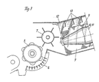
- the front part of a self-propelled combine is designated, which is equipped in a manner known per se with a front cutter bowl 2 and an adjoining inclined conveyor channel 3. From the latter, the crop arrives at a tangential threshing mechanism 4, which consists of a threshing drum 5 and a threshing basket 6 assigned to it. The straw, which has mostly already been threshed out, is then transferred from the transfer drum 7 one after the other Hand over threshing and separating device 8 axial flow system.
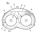
- This re-threshing and separating device 8 essentially consists of 2 rotors 10 and 11, which run parallel to one another in the direction of travel and are provided with a strip 9, which are frustoconical in the receiving area.
- Both rotors can be driven clockwise and surrounded by a common housing 12 which is perforated in some areas.
- the inside of the housing 12 is equipped with guide rails 13 which are fixed to the housing and which, viewed at a distance from one another and counter to the direction of travel, run obliquely to the rear.
- the housing 12 is widened in the upper region, so that a space 14 is formed above the rotors 10 and 11, in which the material thrown upwards by the left rotor 10 can expand, whereupon it is then from the right rotor 11 is detected and compressed again. This measure significantly improves the residual grain separation, since the residual grains located inside the transported straw mat can also escape to the outside.
- a large inlet wedge 16 is formed between the rotor 11 and the wall part 15, which ensures that the expanded straw mat is drawn in by the rotor 11 is accomplished.
- the guide strips 13 are widened to form a circular section 17, the chord 18 of which runs a short distance above the enveloping circles of the rotors 10 and 11.
Landscapes
- Life Sciences & Earth Sciences (AREA)
- Environmental Sciences (AREA)
- Threshing Machine Elements (AREA)
Applications Claiming Priority (2)
| Application Number | Priority Date | Filing Date | Title |
|---|---|---|---|
| DE3932370A DE3932370A1 (de) | 1989-09-28 | 1989-09-28 | Selbstfahrender maehdrescher |
| DE3932370 | 1989-09-28 |
Publications (2)
| Publication Number | Publication Date |
|---|---|
| EP0419786A1 true EP0419786A1 (fr) | 1991-04-03 |
| EP0419786B1 EP0419786B1 (fr) | 1994-04-06 |
Family
ID=6390375
Family Applications (1)
| Application Number | Title | Priority Date | Filing Date |
|---|---|---|---|
| EP90113821A Expired - Lifetime EP0419786B1 (fr) | 1989-09-28 | 1990-07-19 | Moissonneuse-batteuse automotrice |
Country Status (7)
| Country | Link |
|---|---|
| US (1) | US5078646A (fr) |
| EP (1) | EP0419786B1 (fr) |
| DD (1) | DD298036A5 (fr) |
| DE (2) | DE3932370A1 (fr) |
| DK (1) | DK0419786T3 (fr) |
| FI (1) | FI93599C (fr) |
| RU (1) | RU2021669C1 (fr) |
Cited By (1)
| Publication number | Priority date | Publication date | Assignee | Title |
|---|---|---|---|---|
| EP0622014A1 (fr) * | 1993-04-26 | 1994-11-02 | Deere & Company | Elément attaquant la récolte pour séparateur à écoulement axial |
Families Citing this family (17)
| Publication number | Priority date | Publication date | Assignee | Title |
|---|---|---|---|---|
| US5334093A (en) * | 1991-05-10 | 1994-08-02 | Deere & Company | Detachable covers for an axial separator |
| DE4232450A1 (de) * | 1992-09-28 | 1994-03-31 | Claas Ohg | Selbstfahrender Mähdrescher |
| US5556337A (en) * | 1992-09-28 | 1996-09-17 | Claas Ohg Beschraebkt Haftende Offene | Self-propelling harvester thresher |
| AU676037B2 (en) * | 1993-07-01 | 1997-02-27 | Deere & Company | An axial flow combine having a concentric threshing section and an eccentric separation section |
| US5688170A (en) * | 1993-07-01 | 1997-11-18 | Deere & Company | Rotary combine having a concentric infeed section and eccentric threshing and separating sections |
| DE19722079A1 (de) * | 1997-05-27 | 1998-12-03 | Claas Selbstfahr Erntemasch | Einzugsbereich eines Axialabscheiders |
| DE10019667A1 (de) * | 2000-04-19 | 2002-01-03 | Claas Selbstfahr Erntemasch | Selbstfahrender Mähdrescher |
| DE10019640A1 (de) * | 2000-04-19 | 2002-04-18 | Claas Selbstfahr Erntemasch | Selbstfahrender Mähdrescher |
| RU2363140C1 (ru) * | 2008-01-21 | 2009-08-10 | Федеральное государственное образовательное учреждение высшего профессионального образования "Кубанский государственный аграрный университет" | Молотильно-сепарирующее устройство |
| GB2467182A (en) * | 2009-01-27 | 2010-07-28 | Agco As | Combine harvesters |
| DE102010037416A1 (de) * | 2010-09-09 | 2012-03-15 | Claas Selbstfahrende Erntemaschinen Gmbh | Abscheideaggregat für einen Mähdrescher |
| DE102011088543B4 (de) | 2011-12-14 | 2024-11-14 | Deere & Company | Mähdrescher mit einer zwischen der Drescheinrichtung und der Reinigung angeordneten Nachdrescheinrichtung |
| US8540559B1 (en) * | 2012-06-12 | 2013-09-24 | Cnh America Llc | Combine varying dimensional vane threshing system |
| US8636568B1 (en) | 2012-07-11 | 2014-01-28 | Cnh America Llc | Combine stepped threshing chamber |
| BE1021135B1 (nl) | 2013-03-07 | 2016-01-08 | Cnh Industrial Belgium Nv | Rotorbehuizing samenstel voor een oogstmachine |
| BR102016023877B1 (pt) * | 2015-10-16 | 2021-09-14 | Cnh Industrial America Llc | Colheitadeira agrícola |
| US11147214B2 (en) | 2019-06-26 | 2021-10-19 | Deere & Company | Combine with a pre-thresher |
Citations (4)
| Publication number | Priority date | Publication date | Assignee | Title |
|---|---|---|---|---|
| DE2830162A1 (de) * | 1978-07-08 | 1980-01-17 | Deere & Co | Axial-, dresch- und trennvorrichtung fuer maehdrescher |
| US4291709A (en) * | 1980-07-02 | 1981-09-29 | Sperry Corporation | Infeed geometry |
| DE3139933A1 (de) * | 1981-10-08 | 1983-04-28 | Claas Ohg, 4834 Harsewinkel | Selbstfahrender maehdrescher in axialflussbauart |
| US4739773A (en) * | 1986-05-09 | 1988-04-26 | Deere & Company | Feeding arrangement for an axial flow rotary separator |
Family Cites Families (9)
| Publication number | Priority date | Publication date | Assignee | Title |
|---|---|---|---|---|
| US3529645A (en) * | 1968-09-24 | 1970-09-22 | Int Harvester Co | Axial-flow sheller and grinder combine |
| US3794047A (en) * | 1971-08-27 | 1974-02-26 | Sperry Rand Corp | Crop feeding means for an axial flow combine having side by side threshing units |
| US3742686A (en) * | 1972-05-10 | 1973-07-03 | Sperry Rand Corp | Axial flow combine harvester |
| US4611605A (en) * | 1984-08-29 | 1986-09-16 | Deere & Company | Axial flow rotary separator |
| US4611606A (en) * | 1984-08-29 | 1986-09-16 | Deere & Company | Feeding arrangement for an axial flow rotary separator |
| US4884994A (en) * | 1984-08-29 | 1989-12-05 | Deere & Company | Axial flow rotary separator |
| DE3537959C2 (de) * | 1985-10-25 | 1995-02-23 | Claas Ohg | Selbstfahrender Mähdrescher |
| US4875890A (en) * | 1988-02-29 | 1989-10-24 | Ford New Holland, Inc. | Feed plate assembly for axial flow combine |
| US4986794A (en) * | 1990-04-03 | 1991-01-22 | J. I. Case Company | Rotor assembly for an axial-flow combine |
-
1989
- 1989-09-28 DE DE3932370A patent/DE3932370A1/de not_active Withdrawn
-
1990
- 1990-07-19 EP EP90113821A patent/EP0419786B1/fr not_active Expired - Lifetime
- 1990-07-19 DE DE90113821T patent/DE59005251D1/de not_active Expired - Fee Related
- 1990-07-19 DK DK90113821.4T patent/DK0419786T3/da active
- 1990-08-28 US US07/574,297 patent/US5078646A/en not_active Expired - Lifetime
- 1990-09-03 FI FI904338A patent/FI93599C/fi not_active IP Right Cessation
- 1990-09-27 DD DD90344234A patent/DD298036A5/de not_active IP Right Cessation
- 1990-09-27 RU SU904831253A patent/RU2021669C1/ru not_active IP Right Cessation
Patent Citations (4)
| Publication number | Priority date | Publication date | Assignee | Title |
|---|---|---|---|---|
| DE2830162A1 (de) * | 1978-07-08 | 1980-01-17 | Deere & Co | Axial-, dresch- und trennvorrichtung fuer maehdrescher |
| US4291709A (en) * | 1980-07-02 | 1981-09-29 | Sperry Corporation | Infeed geometry |
| DE3139933A1 (de) * | 1981-10-08 | 1983-04-28 | Claas Ohg, 4834 Harsewinkel | Selbstfahrender maehdrescher in axialflussbauart |
| US4739773A (en) * | 1986-05-09 | 1988-04-26 | Deere & Company | Feeding arrangement for an axial flow rotary separator |
Cited By (1)
| Publication number | Priority date | Publication date | Assignee | Title |
|---|---|---|---|---|
| EP0622014A1 (fr) * | 1993-04-26 | 1994-11-02 | Deere & Company | Elément attaquant la récolte pour séparateur à écoulement axial |
Also Published As
| Publication number | Publication date |
|---|---|
| FI93599C (fi) | 1995-05-10 |
| DK0419786T3 (da) | 1994-08-08 |
| FI93599B (fi) | 1995-01-31 |
| FI904338A0 (fi) | 1990-09-03 |
| US5078646A (en) | 1992-01-07 |
| RU2021669C1 (ru) | 1994-10-30 |
| DE59005251D1 (de) | 1994-05-11 |
| EP0419786B1 (fr) | 1994-04-06 |
| DE3932370A1 (de) | 1991-04-11 |
| DD298036A5 (de) | 1992-02-06 |
Similar Documents
| Publication | Publication Date | Title |
|---|---|---|
| EP0419786B1 (fr) | Moissonneuse-batteuse automotrice | |
| DE3429468C2 (de) | Selbstfahrender Mähdrescher | |
| EP0624310A1 (fr) | Dispositif de nettoyage en particulier pour moissonneuse-batteuse | |
| EP0230276A1 (fr) | Moissonneuse-batteuse automotrice | |
| DE3303952C2 (de) | Axialdresch- und Trennvorrichtung | |
| EP1147702A1 (fr) | Moissonneuse-batteuse automotrice | |
| DE3139933C2 (fr) | ||
| DE3135118A1 (de) | Maehdrescher mit axialdreschmaschine | |
| DE3239552C2 (fr) | ||
| EP0339213B1 (fr) | Moissonneuse-batteuse | |
| DE69423980T2 (de) | Apparat zum fördern von spreu, abfallgetreide, kleinkörnern usw. in einer erntemaschine | |
| DE2923022C2 (fr) | ||
| DE3409951C2 (de) | Axialdresch- und Trennvorrichtung | |
| DE3023756A1 (de) | Selbstfahrender maehdrescher | |
| DD276616A1 (de) | Reinigungseinrichtung fuer maehdrescher | |
| DE3223927A1 (de) | Selbstfahrender maehdrescher | |
| DE3245146C2 (de) | Selbstfahrender Mähdrescher nach dem Axialflußsystem | |
| EP0087488B1 (fr) | Dispositif de nettoyage pour moissonneuses-batteuses | |
| DD258161A1 (de) | Mehrebenen-reinigungseinrichtung fuer maehdrescher | |
| DE19815730A1 (de) | Abscheideelement, Abscheidevorrichtung und Erntemaschine | |
| DE2943597C2 (de) | Vollernter für Maiskolbenschrot | |
| DE3503950A1 (de) | Reinigungsvorrichtung fuer maehdrescher | |
| DE3631261A1 (de) | Schuettlerloser maehdrescher | |
| DE941395C (de) | Dreschmaschine, insbesondere Maehdrescher, ohne Strohschuettler | |
| DE3322805A1 (de) | Selbstfahrender maehdrescher nach dem axialflusssystem |
Legal Events
| Date | Code | Title | Description |
|---|---|---|---|
| PUAI | Public reference made under article 153(3) epc to a published international application that has entered the european phase |
Free format text: ORIGINAL CODE: 0009012 |
|
| 17P | Request for examination filed |
Effective date: 19901203 |
|
| AK | Designated contracting states |
Kind code of ref document: A1 Designated state(s): BE DE DK FR IT |
|
| 17Q | First examination report despatched |
Effective date: 19930426 |
|
| RAP1 | Party data changed (applicant data changed or rights of an application transferred) |
Owner name: CLAAS OHG BESCHRAENKT HAFTENDE OFFENE HANDELSGESEL |
|
| GRAA | (expected) grant |
Free format text: ORIGINAL CODE: 0009210 |
|
| AK | Designated contracting states |
Kind code of ref document: B1 Designated state(s): BE DE DK FR IT |
|
| ITF | It: translation for a ep patent filed | ||
| REF | Corresponds to: |
Ref document number: 59005251 Country of ref document: DE Date of ref document: 19940511 |
|
| REG | Reference to a national code |
Ref country code: DK Ref legal event code: T3 |
|
| ET | Fr: translation filed | ||
| PLBE | No opposition filed within time limit |
Free format text: ORIGINAL CODE: 0009261 |
|
| STAA | Information on the status of an ep patent application or granted ep patent |
Free format text: STATUS: NO OPPOSITION FILED WITHIN TIME LIMIT |
|
| 26N | No opposition filed | ||
| PGFP | Annual fee paid to national office [announced via postgrant information from national office to epo] |
Ref country code: DK Payment date: 19990716 Year of fee payment: 10 |
|
| PG25 | Lapsed in a contracting state [announced via postgrant information from national office to epo] |
Ref country code: DK Free format text: LAPSE BECAUSE OF NON-PAYMENT OF DUE FEES Effective date: 20000719 |
|
| REG | Reference to a national code |
Ref country code: DK Ref legal event code: EBP |
|
| PG25 | Lapsed in a contracting state [announced via postgrant information from national office to epo] |
Ref country code: IT Free format text: LAPSE BECAUSE OF NON-PAYMENT OF DUE FEES;WARNING: LAPSES OF ITALIAN PATENTS WITH EFFECTIVE DATE BEFORE 2007 MAY HAVE OCCURRED AT ANY TIME BEFORE 2007. THE CORRECT EFFECTIVE DATE MAY BE DIFFERENT FROM THE ONE RECORDED. Effective date: 20050719 |
|
| PGFP | Annual fee paid to national office [announced via postgrant information from national office to epo] |
Ref country code: DE Payment date: 20070619 Year of fee payment: 18 |
|
| PGFP | Annual fee paid to national office [announced via postgrant information from national office to epo] |
Ref country code: BE Payment date: 20070724 Year of fee payment: 18 |
|
| PGFP | Annual fee paid to national office [announced via postgrant information from national office to epo] |
Ref country code: FR Payment date: 20080718 Year of fee payment: 19 |
|
| PG25 | Lapsed in a contracting state [announced via postgrant information from national office to epo] |
Ref country code: DE Free format text: LAPSE BECAUSE OF NON-PAYMENT OF DUE FEES Effective date: 20090203 |
|
| REG | Reference to a national code |
Ref country code: FR Ref legal event code: ST Effective date: 20100331 |
|
| PG25 | Lapsed in a contracting state [announced via postgrant information from national office to epo] |
Ref country code: FR Free format text: LAPSE BECAUSE OF NON-PAYMENT OF DUE FEES Effective date: 20090731 |
|
| PG25 | Lapsed in a contracting state [announced via postgrant information from national office to epo] |
Ref country code: BE Free format text: LAPSE BECAUSE OF NON-PAYMENT OF DUE FEES Effective date: 20080731 |