EP0419875A2 - Lichtübertragungsgerät - Google Patents
Lichtübertragungsgerät Download PDFInfo
- Publication number
- EP0419875A2 EP0419875A2 EP90116577A EP90116577A EP0419875A2 EP 0419875 A2 EP0419875 A2 EP 0419875A2 EP 90116577 A EP90116577 A EP 90116577A EP 90116577 A EP90116577 A EP 90116577A EP 0419875 A2 EP0419875 A2 EP 0419875A2
- Authority
- EP
- European Patent Office
- Prior art keywords
- light communication
- communication apparatus
- photo
- connector
- coupling member
- Prior art date
- Legal status (The legal status is an assumption and is not a legal conclusion. Google has not performed a legal analysis and makes no representation as to the accuracy of the status listed.)
- Ceased
Links
- 238000004891 communication Methods 0.000 title claims abstract description 76
- 230000008878 coupling Effects 0.000 claims abstract description 20
- 238000010168 coupling process Methods 0.000 claims abstract description 20
- 238000005859 coupling reaction Methods 0.000 claims abstract description 20
- 230000003287 optical effect Effects 0.000 claims description 18
- 238000000034 method Methods 0.000 claims description 13
- 238000000465 moulding Methods 0.000 claims description 7
- 239000013307 optical fiber Substances 0.000 claims description 7
- 230000002093 peripheral effect Effects 0.000 claims description 6
- 239000000463 material Substances 0.000 claims description 4
- 238000006073 displacement reaction Methods 0.000 claims description 2
- 238000003780 insertion Methods 0.000 claims description 2
- 230000037431 insertion Effects 0.000 claims description 2
- 230000015572 biosynthetic process Effects 0.000 claims 1
- 238000004519 manufacturing process Methods 0.000 description 6
- 239000000758 substrate Substances 0.000 description 3
- 239000002184 metal Substances 0.000 description 2
Images




Classifications
-
- G—PHYSICS
- G02—OPTICS
- G02B—OPTICAL ELEMENTS, SYSTEMS OR APPARATUS
- G02B6/00—Light guides; Structural details of arrangements comprising light guides and other optical elements, e.g. couplings
- G02B6/24—Coupling light guides
- G02B6/42—Coupling light guides with opto-electronic elements
- G02B6/4201—Packages, e.g. shape, construction, internal or external details
- G02B6/4246—Bidirectionally operating package structures
-
- B—PERFORMING OPERATIONS; TRANSPORTING
- B29—WORKING OF PLASTICS; WORKING OF SUBSTANCES IN A PLASTIC STATE IN GENERAL
- B29C—SHAPING OR JOINING OF PLASTICS; SHAPING OF MATERIAL IN A PLASTIC STATE, NOT OTHERWISE PROVIDED FOR; AFTER-TREATMENT OF THE SHAPED PRODUCTS, e.g. REPAIRING
- B29C70/00—Shaping composites, i.e. plastics material comprising reinforcements, fillers or preformed parts, e.g. inserts
- B29C70/68—Shaping composites, i.e. plastics material comprising reinforcements, fillers or preformed parts, e.g. inserts by incorporating or moulding on preformed parts, e.g. inserts or layers, e.g. foam blocks
-
- G—PHYSICS
- G02—OPTICS
- G02B—OPTICAL ELEMENTS, SYSTEMS OR APPARATUS
- G02B6/00—Light guides; Structural details of arrangements comprising light guides and other optical elements, e.g. couplings
- G02B6/24—Coupling light guides
- G02B6/42—Coupling light guides with opto-electronic elements
- G02B6/4292—Coupling light guides with opto-electronic elements the light guide being disconnectable from the opto-electronic element, e.g. mutually self aligning arrangements
Definitions
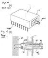
- FIGURES 4(a) and 4(b) show a conventional light communication apparatus unit in a perspective view and a partly sectional view respectively.
- the light communication apparatus unit 10 shown in FIGURES 4(a) and 4(b) includes photo-connector receptacle 41 attached on a side surface of housing 11, optical element 43 mounted on photo-connector receptacle 41, and peripheral circuit 44 of optical element 43 housed within the housing 11 and electrically connected with optical element 43.
- the photo-connector receptacle 41 is attached so as to penetrate housing 11.
- Optical element 43 is supported by a holder 45 integrally formed with optical member 47 lens the like, and mounted on an end portion of photo-connector receptacle 41 inside housing 11.
- Sleeve 46 is provided interior the section of photo-connector receptacle 41 exposed outside housing 11 so that a photo-connector plug attached to an optical fiber can be connected with high precision.
- terminal 42 for electrically connecting light communication apparatus unit 10 with another electric circuit, are provided so as to be exposed outside the housing 11.
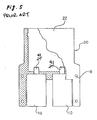
- FIGURE 5 shows a partly sectional plan view of a light communication apparatus including two communication apparatus units of the type described above.
- the light communication apparatus in FIGURE 5 is mainly constituted by preceptacle body 22 and two light communication apparatus units 10.
- Photo-connector receptacles 41 of respective light communication apparatus units 10 in combination with receptacle body 22 constitute two-core-photo- connector receptacle 20.
- a two-core photo-connector plug can be connected to two-core photo-connector receptacle 20 so that optical fibers can be on and off, respectively, in the two light communication apparatus units 10 at the same time.
- Bolt holes 9 are provided at four places in the receptacle body 22 so that the receptacle body 22 can be fixed to a substrate or the like.
- FIGURES 6(a) and 6(c) show the steps of assembling the light communication apparatus of FIGURE 5 on a substrate.
- jig 23 is inserted from the top end of receptacle body 22 and the two light communication apparatus units 10 from the rear end.
- the respective positions of the light communication apparatus units 10 are determined relative to receptacle body 22.
- Jig 23 has a shape substantially the same as that of the two-core photo-connector plug connected to the two-core photo-connector receptacle 20 shown in FIGURE 5.
- the positions of the two light communication apparatus units 10 are determined so as to comprise a two-core connector receptacle together with receptacle body 22.
- terminal 12 is soldered in a predetermined position on substrate 25.
- the receptacle body 22 is fixed by bolts 26 and nuts 27, thereby completing a light communication apparatus.
- the positions of light communication apparatus units 10 are determined by use of jig 23, so that errors ⁇ x, ⁇ y, ⁇ z and ⁇ in the directions indicated in FIGURE 7 are restrained within allowable limits.
- housings of respective light communication apparatus units have been made of metal independently, thereby greatly inflating the cost of these portions.
- Another object of the present invention is to provide a light communication apparatus that can be mass-produced at a low price.
- the light communication apparatus comprises a plurality of light communication apparatus units, each including an optical element, a peripheral circuit of the optical element and a photo-connector receptacle capable of being connected with a photo-connector plug attached to an optical fiber so as to optically combine the optical element with the optical fiber when connected.
- At least the photo-connector receptacles of the plurality of light communication apparatus units are integrated with one another via a coupling member so as to constitute a multi-core photo-connector receptacle capable of being connected with a multi-core photo-connector plug formed by integrated photo-connector plugs which number the same as the light communication apparatus units, the multi-core photo-connector receptacle being of an integral molding type wherein the plurality of photo-connector receptacles are buried so as to be pre-positioned in the coupling member.
- the light communication apparatus according to the present invention has a main feature being that the multi-core photo-connector receptacle thereof is of an integral molding type. That is, the light communication apparatus according to the present invention is superior for mass production as compared with the prior art since it is unnecessary to determine the positions of photo-connector receptacles during assembly of the present invention.
- light communication apparatus units are housed in a housing formed integrally with the above-mentioned integral molding multi-core photo-connector receptacle.
- FIGURES 1(a) and 1(b) illustrate the configuration of an embodiment of the light communication apparatus according to the present invention with FIGURES 1(a) and 1(b) being a partly cut-away perspective view and an exploded perspective view respectively.
- FIGURE 2 is an enlarged sectional view showing part of the light communication apparatus.
- photo-connector receptacles 21 of two light communication apparatus units 10 are buried in and integrated with coupling member 1 so as to constitute two-core photo-connector receptacle 2.
- coupling member 1 is made of a plastic material
- photo-connector receptacles 21 are made of metal and buried in wall 15 at the time of forming coupling member 1.
- Fixing pins 19 are also buried in the coupling member 1.
- Photo-connector receptacles 21 penetrate the wall 5 of the coupling member 1, and rear ends 28 of the photo-connector receptacles 21 are projected slightly inside housing 8 formed integrally with coupling member 1 in the rear end thereof.
- a sleeve 6 is inserted from the rear end 28 of each of photo-connector receptacles 21.
- the sleeve 6 has a double structure such that an inner split sleeve portion thereof acts to make a ferrule align with high accuracy and an outer split sleeve portion acts to press the inner split sleeve so as by an outer split sleeve so that the inner split sleeve is prevented from over expansion so that the ferrule is not broken.
- the insertion length l of holder 5 is made long enough so that there occurs no displacement in an optical axis when the older 5 is inserted.
- flanges 24 are provided on each photo-connector receptacle 21 so that the photo-connector receptacle 21 is steadily fixed when buried in wall 15.
- Optical elements 3 are electrically connected with respective peripheral circuits 4 provided in the housing and the peripheral circuits 4 are electrically connected with terminals 12 which can be connected to a circuit outside housing 8.
- FIGURES 3(a) to 3(d) show the steps of a procedure of producing, by an insert molding method, the above-mentioned coupling member 1 in which photo-connector receptacles 21 of the light communication apparatus are buried.
- a mold 13 having such a shape as shown in FIGURE 3(a) is prepared. Mold 13 has portions 210 finished with sufficient precision so that the photo-connector receptacles 21 can be buried therein.
- the photo-connector receptacles 21 and the pins 19 are attached to the mold 13.
- plastic material 14 is injected into mold 13, and when the plastic has solidified, the product is extracted from mold 13, thereby completing a coupling member 1 as shown in FIGURE 3(d).
- photo-connector receptacles 21 are buried with high precision in coupling member 1 prepared by the above-mentioned method, it is unnecessary to determine the positions of photo-connector receptacles 1 using a jig or the like during an assembly process.
- the light communication apparatus according to the present invention is therefore better suited for mass production.
- coupling member 1 is formed integrally with housing 8 as in this embodiment, it is possible to reduce cost by a large factor.
- a multi-core photo-connector receptacle is formed integrally so that it is possible to eliminate adjustment during the assembly process, and it is therefore possible to provide a light communication apparatus better suited for mass production. It is further possible to increase the percentage of the invention constructed from plastic portion. It is also possible to reduce the number of parts to thereby reduce production cost.
Landscapes
- Physics & Mathematics (AREA)
- General Physics & Mathematics (AREA)
- Optics & Photonics (AREA)
- Chemical & Material Sciences (AREA)
- Engineering & Computer Science (AREA)
- Composite Materials (AREA)
- Mechanical Engineering (AREA)
- Optical Couplings Of Light Guides (AREA)
- Mechanical Coupling Of Light Guides (AREA)
Applications Claiming Priority (2)
| Application Number | Priority Date | Filing Date | Title |
|---|---|---|---|
| JP254731/89 | 1989-09-29 | ||
| JP1254731A JPH03116107A (ja) | 1989-09-29 | 1989-09-29 | 光通信器 |
Publications (2)
| Publication Number | Publication Date |
|---|---|
| EP0419875A2 true EP0419875A2 (de) | 1991-04-03 |
| EP0419875A3 EP0419875A3 (en) | 1992-07-08 |
Family
ID=17269073
Family Applications (1)
| Application Number | Title | Priority Date | Filing Date |
|---|---|---|---|
| EP19900116577 Ceased EP0419875A3 (en) | 1989-09-29 | 1990-08-29 | Light communication apparatus |
Country Status (3)
| Country | Link |
|---|---|
| US (1) | US5109454A (de) |
| EP (1) | EP0419875A3 (de) |
| JP (1) | JPH03116107A (de) |
Cited By (1)
| Publication number | Priority date | Publication date | Assignee | Title |
|---|---|---|---|---|
| EP0947062A4 (de) * | 1996-12-31 | 2003-08-27 | Motorola Inc | Übertragungsvorrichtung mit elektronischem gerät und übertragungsverfahren zwischen elektronischen geräten |
Families Citing this family (27)
| Publication number | Priority date | Publication date | Assignee | Title |
|---|---|---|---|---|
| US5005939A (en) * | 1990-03-26 | 1991-04-09 | International Business Machines Corporation | Optoelectronic assembly |
| US5275765A (en) * | 1991-01-23 | 1994-01-04 | Sumitomo Electric Industries, Ltd. | Method of manufacturing an optical module using a mold die |
| JP2576066Y2 (ja) * | 1992-03-30 | 1998-07-09 | 日本碍子株式会社 | 光−電気信号変換ユニット |
| JPH05343709A (ja) * | 1992-06-08 | 1993-12-24 | Sumitomo Electric Ind Ltd | ピッグテール型光モジュールの製造方法 |
| JP3301791B2 (ja) * | 1992-11-30 | 2002-07-15 | アジレント・テクノロジーズ・インク | 光コネクタ |
| US5361317A (en) * | 1993-06-14 | 1994-11-01 | Motorola, Inc. | Assembly with fixture aligning and affixing an optical fiber to an optical device |
| US5475778A (en) * | 1993-10-21 | 1995-12-12 | Motorola, Inc. | Smart optical coupler and smart optical coupler system |
| USRE40150E1 (en) | 1994-04-25 | 2008-03-11 | Matsushita Electric Industrial Co., Ltd. | Fiber optic module |
| US5578834A (en) * | 1994-06-21 | 1996-11-26 | Tracker Technologies, Inc. | Electrical/optical interface coupler |
| US5515467A (en) * | 1994-12-30 | 1996-05-07 | Motorola, Inc. | Optical fiber assembly for connecting photonic devices to a fiber optic cable |
| US5559919A (en) * | 1995-05-25 | 1996-09-24 | Eaton Corporation | Photoelectric optical fiber connector and sensor apparatus |
| US5668654A (en) * | 1995-05-30 | 1997-09-16 | The Whitaker Corporation | Package for an infrared communications adapter |
| FR2759847B1 (fr) * | 1997-02-14 | 1999-05-07 | Egide Sa | Boitier opto-electronique a insert ceramique |
| US6369924B1 (en) | 1998-04-20 | 2002-04-09 | Stratos Lightwave, Inc. | Optical transceiver with enhanced shielding and related methods |
| US6901221B1 (en) | 1999-05-27 | 2005-05-31 | Jds Uniphase Corporation | Method and apparatus for improved optical elements for vertical PCB fiber optic modules |
| US6213651B1 (en) | 1999-05-26 | 2001-04-10 | E20 Communications, Inc. | Method and apparatus for vertical board construction of fiber optic transmitters, receivers and transceivers |
| US6873800B1 (en) * | 1999-05-26 | 2005-03-29 | Jds Uniphase Corporation | Hot pluggable optical transceiver in a small form pluggable package |
| US7013088B1 (en) | 1999-05-26 | 2006-03-14 | Jds Uniphase Corporation | Method and apparatus for parallel optical interconnection of fiber optic transmitters, receivers and transceivers |
| US20010048793A1 (en) * | 1999-05-27 | 2001-12-06 | Edwin Dair | Method and apparatus for multiboard fiber optic modules and fiber optic module arrays |
| US7116912B2 (en) * | 1999-05-27 | 2006-10-03 | Jds Uniphase Corporation | Method and apparatus for pluggable fiber optic modules |
| US6952532B2 (en) * | 1999-05-27 | 2005-10-04 | Jds Uniphase Corporation | Method and apparatus for multiboard fiber optic modules and fiber optic module arrays |
| US20010030789A1 (en) * | 1999-05-27 | 2001-10-18 | Wenbin Jiang | Method and apparatus for fiber optic modules |
| US6635866B2 (en) | 2001-04-19 | 2003-10-21 | Internation Business Machines Corporation | Multi-functional fiber optic coupler |
| JP3928720B2 (ja) | 2003-01-07 | 2007-06-13 | セイコーエプソン株式会社 | 強誘電体記憶装置 |
| DE102009046401B4 (de) * | 2009-11-04 | 2012-08-09 | Areva Np Gmbh | Verfahren und Vorrichtung zur Bearbeitung eines Dichtsitzes einer Absperrarmatur |
| CN102565961B (zh) * | 2012-01-18 | 2013-11-27 | 安费诺光纤技术(深圳)有限公司 | 一种一体式光衰减器 |
| US9246595B2 (en) * | 2013-12-09 | 2016-01-26 | Neophotonics Corporation | Small packaged tunable laser transmitter |
Family Cites Families (10)
| Publication number | Priority date | Publication date | Assignee | Title |
|---|---|---|---|---|
| FR2175547B1 (de) * | 1972-03-13 | 1978-12-08 | Fort Francois | |
| US4427879A (en) * | 1975-04-18 | 1984-01-24 | Allied Corporation | Optoelectronic connector assembly |
| US4173389A (en) * | 1977-09-28 | 1979-11-06 | Bell Telephone Laboratories, Incorporated | Molded optical fiber connector |
| US4268756A (en) * | 1978-11-13 | 1981-05-19 | Trw Inc. | Optical transceiver |
| DE3172553D1 (en) * | 1980-11-28 | 1985-11-07 | Toshiba Kk | Method for manufacturing a module for a fiber optic link |
| US4722586A (en) * | 1985-04-12 | 1988-02-02 | Tektronix, Inc. | Electro-optical transducer module |
| US4818056A (en) * | 1987-03-02 | 1989-04-04 | Tektronix, Inc. | Optical connector with direct mounted photo diode |
| US4840451A (en) * | 1987-12-08 | 1989-06-20 | Molex Incorporated | Shielded fiber optic connector assembly |
| CA2036727C (en) * | 1990-03-13 | 1998-12-22 | Hisao Go | Optical module including receptacle, and method of producing the same |
| US5005939A (en) * | 1990-03-26 | 1991-04-09 | International Business Machines Corporation | Optoelectronic assembly |
-
1989
- 1989-09-29 JP JP1254731A patent/JPH03116107A/ja active Pending
-
1990
- 1990-08-29 EP EP19900116577 patent/EP0419875A3/en not_active Ceased
- 1990-08-29 US US07/574,219 patent/US5109454A/en not_active Expired - Fee Related
Cited By (1)
| Publication number | Priority date | Publication date | Assignee | Title |
|---|---|---|---|---|
| EP0947062A4 (de) * | 1996-12-31 | 2003-08-27 | Motorola Inc | Übertragungsvorrichtung mit elektronischem gerät und übertragungsverfahren zwischen elektronischen geräten |
Also Published As
| Publication number | Publication date |
|---|---|
| US5109454A (en) | 1992-04-28 |
| EP0419875A3 (en) | 1992-07-08 |
| JPH03116107A (ja) | 1991-05-17 |
Similar Documents
| Publication | Publication Date | Title |
|---|---|---|
| US5109454A (en) | Light communication apparatus | |
| US6033125A (en) | Sealed multiposition fiber optic connector | |
| JP2513880B2 (ja) | 光学部品の製造方法 | |
| EP0009330B1 (de) | Lichtleiteradapter | |
| US4410469A (en) | Method for manufacturing a module for a fiber optic link | |
| US5666449A (en) | Optical waveguide device | |
| US6402389B1 (en) | Angled opto-mechanical device | |
| US6341899B1 (en) | Hybrid connector | |
| EP0446711B1 (de) | Optischer Modul mit einer Umhüllung und Verfahren zur Herstellung derselben | |
| US5611014A (en) | Optoelectronic device connecting techniques | |
| JPH075107U (ja) | 装置パッケージとソケットから成る装置 | |
| US6370771B1 (en) | Method for making an electrical connector | |
| US4711521A (en) | Method of manufacturing a terminal device for an optical fiber, and device thus obtained | |
| US6939057B2 (en) | Optical coupling unit and method for inserting optical wave guides into an optical coupling unit | |
| US5841189A (en) | Semiconductor device and manufacturing method thereof | |
| JPS6012519A (ja) | 光導波体プラグ用精密部品 | |
| JPH04239614A (ja) | 光モジュールの製造方法 | |
| JP2973542B2 (ja) | 光モジュール及びその製造装置及びその製造方法 | |
| WO1997042535A1 (en) | Opto-mechanical connector | |
| KR100509771B1 (ko) | 커넥터를 구비한 광 캡슐 | |
| US6533469B1 (en) | Ferrule for connecting optical fibers, method of producing the same and optical fiber connector using the same | |
| JPH0795460B2 (ja) | プラグインコネクタ | |
| US6457876B1 (en) | Surface-mountable optical device | |
| GB2356465A (en) | Optic fibre connector with light emitter and receiver in casing | |
| EP1102099A2 (de) | Hybrider Steckverbinder |
Legal Events
| Date | Code | Title | Description |
|---|---|---|---|
| PUAI | Public reference made under article 153(3) epc to a published international application that has entered the european phase |
Free format text: ORIGINAL CODE: 0009012 |
|
| 17P | Request for examination filed |
Effective date: 19901220 |
|
| AK | Designated contracting states |
Kind code of ref document: A2 Designated state(s): DE GB |
|
| PUAL | Search report despatched |
Free format text: ORIGINAL CODE: 0009013 |
|
| AK | Designated contracting states |
Kind code of ref document: A3 Designated state(s): DE GB |
|
| 17Q | First examination report despatched |
Effective date: 19940503 |
|
| GRAG | Despatch of communication of intention to grant |
Free format text: ORIGINAL CODE: EPIDOS AGRA |
|
| STAA | Information on the status of an ep patent application or granted ep patent |
Free format text: STATUS: THE APPLICATION HAS BEEN REFUSED |
|
| 18R | Application refused |
Effective date: 19960722 |