EP0419949B1 - Tôle de blindage d'étage de rack électronique - Google Patents
Tôle de blindage d'étage de rack électronique Download PDFInfo
- Publication number
- EP0419949B1 EP0419949B1 EP90117600A EP90117600A EP0419949B1 EP 0419949 B1 EP0419949 B1 EP 0419949B1 EP 90117600 A EP90117600 A EP 90117600A EP 90117600 A EP90117600 A EP 90117600A EP 0419949 B1 EP0419949 B1 EP 0419949B1
- Authority
- EP
- European Patent Office
- Prior art keywords
- sheet
- plate
- shield
- subrack
- parallel
- Prior art date
- Legal status (The legal status is an assumption and is not a legal conclusion. Google has not performed a legal analysis and makes no representation as to the accuracy of the status listed.)
- Expired - Lifetime
Links
- 238000013016 damping Methods 0.000 claims description 9
- 230000017525 heat dissipation Effects 0.000 claims description 4
- 230000000712 assembly Effects 0.000 claims description 2
- 238000000429 assembly Methods 0.000 claims description 2
- 230000001419 dependent effect Effects 0.000 claims 1
- 238000012216 screening Methods 0.000 abstract 3
- 229910052751 metal Inorganic materials 0.000 description 3
- 239000002184 metal Substances 0.000 description 3
- 238000007789 sealing Methods 0.000 description 3
- 229910052782 aluminium Inorganic materials 0.000 description 2
- XAGFODPZIPBFFR-UHFFFAOYSA-N aluminium Chemical compound [Al] XAGFODPZIPBFFR-UHFFFAOYSA-N 0.000 description 2
- 238000001816 cooling Methods 0.000 description 2
- 239000010410 layer Substances 0.000 description 2
- 238000009423 ventilation Methods 0.000 description 2
- 238000005452 bending Methods 0.000 description 1
- 238000010276 construction Methods 0.000 description 1
- 238000003780 insertion Methods 0.000 description 1
- 230000037431 insertion Effects 0.000 description 1
- 238000009434 installation Methods 0.000 description 1
- 238000004806 packaging method and process Methods 0.000 description 1
- 238000010079 rubber tapping Methods 0.000 description 1
- 239000002356 single layer Substances 0.000 description 1
Images


Classifications
-
- H—ELECTRICITY
- H05—ELECTRIC TECHNIQUES NOT OTHERWISE PROVIDED FOR
- H05K—PRINTED CIRCUITS; CASINGS OR CONSTRUCTIONAL DETAILS OF ELECTRIC APPARATUS; MANUFACTURE OF ASSEMBLAGES OF ELECTRICAL COMPONENTS
- H05K9/00—Screening of apparatus or components against electric or magnetic fields
- H05K9/0062—Structures of standardised dimensions, e.g. 19" rack, chassis for servers or telecommunications
Definitions
- the invention relates to a single-storey shield plate for a subrack for shielding against high-frequency, electromagnetic interference fields, from the plug-in assemblies plugged into the subrack with low supply voltages and signal levels.
- floor shield plates for a subrack are known.
- Each tiered umbrella plate is folded on all sides.
- the bends on the front of the tiered shielding plate contain pressed-in nuts for self-locking screws.
- This tiered shield plate can be screwed to the side parts of the subrack.
- the tiered screen plate is provided all round with a sealing cord or a contact strip.
- the disadvantage of this multi-level shielding plate is that high attenuation values are not achieved and the cutoff frequency that is to be shielded by the plug-in modules is not very high.
- the front and rear of the subrack are provided with a front plate and a wiring shield plate.
- the individual parts are screwed together, with maximum frequency sealing, in particular those made of metal mesh, being arranged in the parting lines of the housing covers.
- the disadvantage of such a shield is that the heat dissipation from the interior of the housing can only be radiated through the housing walls.
- this filter device with the honeycomb openings increases the housing as a function of the cutoff frequency that is to be shielded. Furthermore, the electrical device alone becomes more expensive due to the filter arrangement with the honeycomb openings.
- the invention is based on the object of improving the perforated baffle shield plate mentioned at the outset in such a way that high shielding attenuation values are achieved.
- the single-level shield plate for a subrack for shielding against high-frequency, electromagnetic interference fields consists of a U-shaped profile, the legs of which are each designed as transverse rails with a longitudinal thread and the perforated web plate on the side facing away from the legs has longitudinal webs arranged parallel to one another and parallel to the legs, each of which has a core hole, the thickness of the web plate and the design of its punched hole pattern depend on the damping and heat dissipation requirements of the plug-in modules arranged in the subrack.
- this tiered umbrella plate can be created by simply cutting it to length in predetermined division steps from an aluminum extruded profile.
- the thickness of the web plate is dimensioned such that the hole pattern can be punched into the web plate, whereby the punch hole pattern is produced economically.
- the single-level shield plate can be screwed directly to the side parts of the subrack, which increases the rigidity of the subrack.
- the longitudinal webs prevent guide rails from bending in the subrack.
- Front and rear shielding plates can be mechanically and electrically connected to the single-layer shielding plate by means of self-tapping screws in the two-sided longitudinal threads of the legs of the side shield plate designed as cross rails.
- the multi-level shield plate is mechanically and electrically connected to the front and rear cross rails of the subrack using screws.
- the damping can be varied via the screw spacing. In order to increase the damping, sealing cords or contact strips are arranged in the parting lines.
- a front and a rear cross rail of a subrack are arranged in one piece on the side of the perforated web plate in the region of the legs parallel to the longitudinal webs. This increases the strength of the subrack while increasing the damping value, since the single-level shield plate only has to be screwed to the side parts of the subrack.
- At least one further additional perforated plate is provided, the punched hole pattern and dimensions of which correspond to those of the web plate, the plate and the web plate being mechanically and electrically conductively connected to one another by means of tubular rivets inserted in the punched holes.
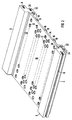
- FIG. 1 shows a multi-level shielding sheet 2 according to the invention for a subrack, which is not shown for reasons of clarity, for shielding against high-frequency electromagnetic interference fields.
- This multi-level shielding plate 2 is intended to prevent high-frequency electromagnetic interference fields with a frequency range ⁇ GHz range from plug-in modules inserted in the module rack with low supply voltages and signal levels, the interference currents flowing away from the shielding components onto the carrier components of the module rack.
- the single-storey shield plate 2 consists of a U-shaped profile, in particular an extruded aluminum profile, which is deflected from the running meter in certain division steps.
- the legs 4 and 6 of the U-shaped profile are each designed as transverse rails with a longitudinal thread 8, also called a thread groove.
- the web plate 10 of the U-shaped profile is provided with holes 12 which are used for cooling the plug-in modules in the rack.
- the design of the hole pattern depends on the predetermined shielding attenuation value and on the cooling requirements of the plug-in modules. For economic reasons, the holes 12 are punched into the web plate 10.
- the side 14 of the web plate 10 facing away from the legs 4 and 6 has longitudinal webs 16 arranged parallel to one another and parallel to the legs 4 and 6.
- Each longitudinal web 16 is provided with a core hole 18.
- the multi-level shield plate 2 can be screwed directly to the side walls of the subrack, the tightness of this connection and thus the predetermined damping value can be varied depending on the distance between the longitudinal webs 16.
- These longitudinal webs 16 also serve for stiffening the subrack or as a support for the guide rails of the subrack.
- the longitudinal thread 8 of the two legs 4 and 6 are provided so that further shielding components, for example front panels and a wiring shield plate, could be mechanically and electrically connected to the floor shield plate 2. This gives you a completely shielded subrack.
- FIG. 2 shows a further embodiment of the tiered umbrella plate 2 according to FIG. 1, the same reference symbols denoting the same elements of the tiered umbrella plate 2.
- a front and rear cross rail 20 and 22 of a module rack are arranged in one piece on the side 14 of the perforated web plate 10 in the region of the legs 4 and 6 parallel to the longitudinal webs 16.
- the front cross rail 20 is provided with two groove-shaped receptacles 24 and 26 which are arranged at right angles to one another and which are formed by End face to end face of the cross rail 20.
- the opening of the groove-shaped receptacle 24 shows the direction of insertion of the plug-in modules and the opening of the groove-shaped receptacle 26 is arranged in the web plate 10.
- the rear cross rail 22 is provided on the one hand with a longitudinal thread 28 and on the other hand with a groove-shaped receptacle 30 for a contact means, the longitudinal thread 28 and the receptacle 30 being arranged at right angles to one another.
- the longitudinal thread 28 is provided for the attachment of a backplane.
- the opening of the groove-shaped receptacle 30, like the opening of the receptacle 26, is arranged in the web plate 10.
- the distance between the two cross rails 20 and 22 is smaller than the distance between the two legs 4 and 6.
- FIG. 3 shows a section of a subrack with shield components.
- the front and rear cross rails 20 and 22, a left side wall 32, a rear wall circuit board 34, a front plate 36 and a wiring shield plate 38 are partially shown from the subrack. All components are screwed together, a contact strip 40 being arranged between the side wall 32 and the tiered shield plate 2.
- two further additional plates 42 and 44 are packaged on the web plate 10. The hole pattern of these two additional plates 42 and 44 corresponds to the hole pattern of the web plate 10.
- the plates 42 and 44 and the web plate 10 are mechanically and electrically connected to one another by means of tubular rivets 46, which are each used in the air passage area, ie in the punched hole 12. This corresponds to the outside diameter of each tubular rivet 46 corresponds to the hole diameter, whereby the passage of air is only insignificantly restricted.
- this packaged multi-level shield plate 2 is connected by screws to the cross rails 20 and 22 of the subrack.
Landscapes
- Engineering & Computer Science (AREA)
- Microelectronics & Electronic Packaging (AREA)
- Shielding Devices Or Components To Electric Or Magnetic Fields (AREA)
- Golf Clubs (AREA)
- Moving Of Heads (AREA)
- Sheets, Magazines, And Separation Thereof (AREA)
- Supporting Of Heads In Record-Carrier Devices (AREA)
Claims (3)
- Tôle de blindage (2) d'étage pour un porte-modules pour réaliser le blindage vis-à-vis de champs électromagnétiques parasites à haute fréquence, constituée par un profilé en forme de U, dont les branches (4,6) sont réalisées respectivement sous la forme de rails transversaux comportant un filetage longitudinal (8) et dont la base en tôle perforée (10) possède, sur la face (14) tournée à l'opposé des branches (4,6), des barrettes longitudinales (16), qui sont parallèles entre elles et aux branches (4,6) et qui possèdent respectivement un avant-trou (18), l'épaisseur de la base en tôle (10) et la configuration du réseau de trous perforés de cette base dépendant des exigences du point de vue affaiblissement et évacuation de chaleur des modules enfichables disposés dans le porte-modules.
- Tôle de blindage (2) d'étage suivant la revendication 1, caractérisée par le fait qu'un rail transversal avant et un rail transversal arrière (20,22) d'un porte-modules sont disposés d'un seul tenant sur la face (14) de la base en tôle perforée (10) au voisinage des branches (4,6), parallèlement aux barrettes longitudinales (16).
- Tôle de blindage (2) d'étage suivant la revendication 1 ou 2, caractérisée par le fait qu'il est prévu au moins une tôle perforée supplémentaire (42,44), dont le réseau des trous poinçonnés et les dimensions correspondent à celui et à celles de la base en tôle (10), la tôle (42,44) et la base en tôle (10) étant reliées entre elles mécaniquement et d'une manière électriquement conductrice au moyen de rivets tubulaires (46) insérés dans les trous poinçonnés (12).
Priority Applications (1)
| Application Number | Priority Date | Filing Date | Title |
|---|---|---|---|
| AT90117600T ATE101472T1 (de) | 1989-09-25 | 1990-09-12 | Etagenschirmblech fuer einen baugruppentraeger. |
Applications Claiming Priority (2)
| Application Number | Priority Date | Filing Date | Title |
|---|---|---|---|
| DE8911405U | 1989-09-25 | ||
| DE8911405U DE8911405U1 (de) | 1989-09-25 | 1989-09-25 | Etagenschirmblech für einen Baugruppenträger |
Publications (3)
| Publication Number | Publication Date |
|---|---|
| EP0419949A2 EP0419949A2 (fr) | 1991-04-03 |
| EP0419949A3 EP0419949A3 (en) | 1992-04-08 |
| EP0419949B1 true EP0419949B1 (fr) | 1994-02-09 |
Family
ID=6843144
Family Applications (1)
| Application Number | Title | Priority Date | Filing Date |
|---|---|---|---|
| EP90117600A Expired - Lifetime EP0419949B1 (fr) | 1989-09-25 | 1990-09-12 | Tôle de blindage d'étage de rack électronique |
Country Status (3)
| Country | Link |
|---|---|
| EP (1) | EP0419949B1 (fr) |
| AT (1) | ATE101472T1 (fr) |
| DE (2) | DE8911405U1 (fr) |
Families Citing this family (4)
| Publication number | Priority date | Publication date | Assignee | Title |
|---|---|---|---|---|
| DE29704237U1 (de) * | 1997-03-08 | 1997-05-28 | DMT GmbH Feinwerktechnische Komplettlösungen, 71034 Böblingen | Gerätegehäuse |
| DE19736026C1 (de) | 1997-08-20 | 1998-10-22 | Dmt Gmbh Feinwerktechnische Ko | Gerätegehäuse |
| DE10149445C1 (de) * | 2001-10-08 | 2002-10-10 | Schroff Gmbh | HF-geschirmter Baugruppenträger |
| US6856512B2 (en) * | 2002-05-15 | 2005-02-15 | Sun Microsystems, Inc. | U-seam |
Family Cites Families (3)
| Publication number | Priority date | Publication date | Assignee | Title |
|---|---|---|---|---|
| DE8422589U1 (de) * | 1984-07-28 | 1984-10-31 | Licentia Patent-Verwaltungs-Gmbh, 6000 Frankfurt | Verbindungseinrichtung |
| DE8714497U1 (de) * | 1987-10-30 | 1987-12-10 | Siemens AG, 1000 Berlin und 8000 München | Etagenschirmblech für einen Baugruppenträger |
| DE8901676U1 (de) * | 1989-02-14 | 1990-06-13 | Klöckner-Moeller Elektrizitätsgesellschaft mbH, 5300 Bonn | Baugruppenträger |
-
1989
- 1989-09-25 DE DE8911405U patent/DE8911405U1/de not_active Expired
-
1990
- 1990-09-12 DE DE90117600T patent/DE59004546D1/de not_active Expired - Fee Related
- 1990-09-12 EP EP90117600A patent/EP0419949B1/fr not_active Expired - Lifetime
- 1990-09-12 AT AT90117600T patent/ATE101472T1/de not_active IP Right Cessation
Also Published As
| Publication number | Publication date |
|---|---|
| EP0419949A2 (fr) | 1991-04-03 |
| ATE101472T1 (de) | 1994-02-15 |
| DE59004546D1 (de) | 1994-03-24 |
| EP0419949A3 (en) | 1992-04-08 |
| DE8911405U1 (de) | 1989-11-16 |
Similar Documents
| Publication | Publication Date | Title |
|---|---|---|
| EP0937317B1 (fr) | Bati electronique pour cartes de circuits avec rails transversaux centraux | |
| EP1935222B1 (fr) | Dispositif electrique | |
| EP0691069B1 (fr) | Panneau arriere de connexion pour chassis equipes | |
| EP0415246B1 (fr) | Rack électronique | |
| DE102020107131B4 (de) | Leistungselektronikeinheit und Kraftfahrzeug | |
| EP0014391B1 (fr) | Système d'unité enfichable et support pour circuits electronique | |
| EP0419949A2 (fr) | Tôle de blindage d'étage de rack électronique | |
| DE19609887C1 (de) | Gerätechassis für elektronische Geräte | |
| EP0886992B1 (fr) | Chassis pour appareils electroniques | |
| DE4126576A1 (de) | Baugruppentraeger | |
| EP0516986A1 (fr) | Rack électronique | |
| AT409047B (de) | Vorrichtung zur erdung einer modular aufgebauten gehäuseeinheit | |
| DE3716828C2 (fr) | ||
| EP4322716B1 (fr) | Boîtier pour circuit électrique et procédé de fabrication associé | |
| DE102024118228A1 (de) | Steuergerät mit einer eine Vielzahl von Durchschrauböffnungen aufweisenden und zwischen zwei Leiterplatten angeordneten Halteeinrichtung und Fahrzeug | |
| EP0939990A1 (fr) | Unite de montage comportant un rail de montage | |
| EP1102527B1 (fr) | Boîtier protégé contre les décharges électrostatiques | |
| EP0884938B1 (fr) | Unité électronique avec blindage métallique dans une zone de connexions | |
| DE2714563C2 (de) | Baugruppenträger | |
| AT521859A1 (de) | Anordnung zum Anschließen von Lichtwellenleitern | |
| EP4618329A1 (fr) | Support de composants | |
| DE19523257C1 (de) | Baugruppenträger | |
| DE19821520C1 (de) | Schirmeinrichtung für eine elektronische Baueinheit | |
| DE9115845U1 (de) | Baugruppenträger | |
| DE19643429C2 (de) | Baugruppenträger |
Legal Events
| Date | Code | Title | Description |
|---|---|---|---|
| PUAI | Public reference made under article 153(3) epc to a published international application that has entered the european phase |
Free format text: ORIGINAL CODE: 0009012 |
|
| 17P | Request for examination filed |
Effective date: 19901205 |
|
| AK | Designated contracting states |
Kind code of ref document: A2 Designated state(s): AT DE FR GB IT SE |
|
| PUAL | Search report despatched |
Free format text: ORIGINAL CODE: 0009013 |
|
| AK | Designated contracting states |
Kind code of ref document: A3 Designated state(s): AT DE FR GB IT SE |
|
| 17Q | First examination report despatched |
Effective date: 19930708 |
|
| GRAA | (expected) grant |
Free format text: ORIGINAL CODE: 0009210 |
|
| AK | Designated contracting states |
Kind code of ref document: B1 Designated state(s): AT DE FR GB IT SE |
|
| REF | Corresponds to: |
Ref document number: 101472 Country of ref document: AT Date of ref document: 19940215 Kind code of ref document: T |
|
| REF | Corresponds to: |
Ref document number: 59004546 Country of ref document: DE Date of ref document: 19940324 |
|
| ITF | It: translation for a ep patent filed | ||
| ET | Fr: translation filed | ||
| GBT | Gb: translation of ep patent filed (gb section 77(6)(a)/1977) |
Effective date: 19940513 |
|
| PLBE | No opposition filed within time limit |
Free format text: ORIGINAL CODE: 0009261 |
|
| STAA | Information on the status of an ep patent application or granted ep patent |
Free format text: STATUS: NO OPPOSITION FILED WITHIN TIME LIMIT |
|
| EAL | Se: european patent in force in sweden |
Ref document number: 90117600.8 |
|
| 26N | No opposition filed | ||
| PGFP | Annual fee paid to national office [announced via postgrant information from national office to epo] |
Ref country code: GB Payment date: 19960821 Year of fee payment: 7 |
|
| PGFP | Annual fee paid to national office [announced via postgrant information from national office to epo] |
Ref country code: AT Payment date: 19960904 Year of fee payment: 7 |
|
| PGFP | Annual fee paid to national office [announced via postgrant information from national office to epo] |
Ref country code: SE Payment date: 19960912 Year of fee payment: 7 |
|
| PGFP | Annual fee paid to national office [announced via postgrant information from national office to epo] |
Ref country code: FR Payment date: 19960926 Year of fee payment: 7 |
|
| PGFP | Annual fee paid to national office [announced via postgrant information from national office to epo] |
Ref country code: DE Payment date: 19961118 Year of fee payment: 7 |
|
| PG25 | Lapsed in a contracting state [announced via postgrant information from national office to epo] |
Ref country code: GB Free format text: LAPSE BECAUSE OF NON-PAYMENT OF DUE FEES Effective date: 19970912 Ref country code: AT Free format text: LAPSE BECAUSE OF NON-PAYMENT OF DUE FEES Effective date: 19970912 |
|
| PG25 | Lapsed in a contracting state [announced via postgrant information from national office to epo] |
Ref country code: SE Free format text: LAPSE BECAUSE OF NON-PAYMENT OF DUE FEES Effective date: 19970913 |
|
| PG25 | Lapsed in a contracting state [announced via postgrant information from national office to epo] |
Ref country code: FR Free format text: THE PATENT HAS BEEN ANNULLED BY A DECISION OF A NATIONAL AUTHORITY Effective date: 19970930 |
|
| GBPC | Gb: european patent ceased through non-payment of renewal fee |
Effective date: 19970912 |
|
| PG25 | Lapsed in a contracting state [announced via postgrant information from national office to epo] |
Ref country code: DE Free format text: LAPSE BECAUSE OF NON-PAYMENT OF DUE FEES Effective date: 19980603 |
|
| EUG | Se: european patent has lapsed |
Ref document number: 90117600.8 |
|
| REG | Reference to a national code |
Ref country code: FR Ref legal event code: ST |
|
| PG25 | Lapsed in a contracting state [announced via postgrant information from national office to epo] |
Ref country code: IT Free format text: LAPSE BECAUSE OF NON-PAYMENT OF DUE FEES;WARNING: LAPSES OF ITALIAN PATENTS WITH EFFECTIVE DATE BEFORE 2007 MAY HAVE OCCURRED AT ANY TIME BEFORE 2007. THE CORRECT EFFECTIVE DATE MAY BE DIFFERENT FROM THE ONE RECORDED. Effective date: 20050912 |