EP0419984B2 - Réglage électro-hydraulique pour une machine hydraulique - Google Patents
Réglage électro-hydraulique pour une machine hydraulique Download PDFInfo
- Publication number
- EP0419984B2 EP0419984B2 EP90117815A EP90117815A EP0419984B2 EP 0419984 B2 EP0419984 B2 EP 0419984B2 EP 90117815 A EP90117815 A EP 90117815A EP 90117815 A EP90117815 A EP 90117815A EP 0419984 B2 EP0419984 B2 EP 0419984B2
- Authority
- EP
- European Patent Office
- Prior art keywords
- responsive
- set forth
- displacement
- control
- machine set
- Prior art date
- Legal status (The legal status is an assumption and is not a legal conclusion. Google has not performed a legal analysis and makes no representation as to the accuracy of the status listed.)
- Expired - Lifetime
Links
- 238000006073 displacement reaction Methods 0.000 claims description 44
- 239000012530 fluid Substances 0.000 claims description 31
- 230000006870 function Effects 0.000 claims description 15
- 238000004891 communication Methods 0.000 claims description 10
- 238000005259 measurement Methods 0.000 claims description 8
- 230000007704 transition Effects 0.000 claims description 4
- 238000010276 construction Methods 0.000 claims description 3
- 230000000977 initiatory effect Effects 0.000 claims description 3
- 239000007787 solid Substances 0.000 claims description 3
- 230000005294 ferromagnetic effect Effects 0.000 claims description 2
- 230000008878 coupling Effects 0.000 claims 2
- 238000010168 coupling process Methods 0.000 claims 2
- 238000005859 coupling reaction Methods 0.000 claims 2
- 230000001939 inductive effect Effects 0.000 claims 1
- 239000003990 capacitor Substances 0.000 description 9
- 238000010586 diagram Methods 0.000 description 8
- 230000006378 damage Effects 0.000 description 7
- 239000004020 conductor Substances 0.000 description 4
- 230000003750 conditioning effect Effects 0.000 description 3
- 125000004122 cyclic group Chemical group 0.000 description 3
- 230000033001 locomotion Effects 0.000 description 3
- 230000004044 response Effects 0.000 description 3
- 230000005540 biological transmission Effects 0.000 description 2
- 230000017525 heat dissipation Effects 0.000 description 2
- 238000009434 installation Methods 0.000 description 2
- 230000005291 magnetic effect Effects 0.000 description 2
- 238000000034 method Methods 0.000 description 2
- 238000012545 processing Methods 0.000 description 2
- 230000000712 assembly Effects 0.000 description 1
- 238000000429 assembly Methods 0.000 description 1
- 230000001934 delay Effects 0.000 description 1
- 238000013461 design Methods 0.000 description 1
- 230000000694 effects Effects 0.000 description 1
- 238000003754 machining Methods 0.000 description 1
- 230000007257 malfunction Effects 0.000 description 1
- 230000000737 periodic effect Effects 0.000 description 1
- 125000006850 spacer group Chemical group 0.000 description 1
- 230000000153 supplemental effect Effects 0.000 description 1
- 238000012546 transfer Methods 0.000 description 1
Images







Classifications
-
- G—PHYSICS
- G05—CONTROLLING; REGULATING
- G05D—SYSTEMS FOR CONTROLLING OR REGULATING NON-ELECTRIC VARIABLES
- G05D16/00—Control of fluid pressure
- G05D16/20—Control of fluid pressure characterised by the use of electric means
- G05D16/2006—Control of fluid pressure characterised by the use of electric means with direct action of electric energy on controlling means
- G05D16/2066—Control of fluid pressure characterised by the use of electric means with direct action of electric energy on controlling means using controlling means acting on the pressure source
-
- F—MECHANICAL ENGINEERING; LIGHTING; HEATING; WEAPONS; BLASTING
- F04—POSITIVE - DISPLACEMENT MACHINES FOR LIQUIDS; PUMPS FOR LIQUIDS OR ELASTIC FLUIDS
- F04B—POSITIVE-DISPLACEMENT MACHINES FOR LIQUIDS; PUMPS
- F04B49/00—Control, e.g. of pump delivery, or pump pressure of, or safety measures for, machines, pumps, or pumping installations, not otherwise provided for, or of interest apart from, groups F04B1/00 - F04B47/00
- F04B49/06—Control using electricity
- F04B49/065—Control using electricity and making use of computers
-
- F—MECHANICAL ENGINEERING; LIGHTING; HEATING; WEAPONS; BLASTING
- F04—POSITIVE - DISPLACEMENT MACHINES FOR LIQUIDS; PUMPS FOR LIQUIDS OR ELASTIC FLUIDS
- F04B—POSITIVE-DISPLACEMENT MACHINES FOR LIQUIDS; PUMPS
- F04B2201/00—Pump parameters
- F04B2201/12—Parameters of driving or driven means
- F04B2201/1201—Rotational speed of the axis
-
- F—MECHANICAL ENGINEERING; LIGHTING; HEATING; WEAPONS; BLASTING
- F04—POSITIVE - DISPLACEMENT MACHINES FOR LIQUIDS; PUMPS FOR LIQUIDS OR ELASTIC FLUIDS
- F04B—POSITIVE-DISPLACEMENT MACHINES FOR LIQUIDS; PUMPS
- F04B2201/00—Pump parameters
- F04B2201/12—Parameters of driving or driven means
- F04B2201/1205—Position of a non-rotating inclined plate
- F04B2201/12051—Angular position
-
- F—MECHANICAL ENGINEERING; LIGHTING; HEATING; WEAPONS; BLASTING
- F04—POSITIVE - DISPLACEMENT MACHINES FOR LIQUIDS; PUMPS FOR LIQUIDS OR ELASTIC FLUIDS
- F04B—POSITIVE-DISPLACEMENT MACHINES FOR LIQUIDS; PUMPS
- F04B2205/00—Fluid parameters
- F04B2205/05—Pressure after the pump outlet
-
- F—MECHANICAL ENGINEERING; LIGHTING; HEATING; WEAPONS; BLASTING
- F04—POSITIVE - DISPLACEMENT MACHINES FOR LIQUIDS; PUMPS FOR LIQUIDS OR ELASTIC FLUIDS
- F04B—POSITIVE-DISPLACEMENT MACHINES FOR LIQUIDS; PUMPS
- F04B2207/00—External parameters
- F04B2207/01—Load in general
-
- F—MECHANICAL ENGINEERING; LIGHTING; HEATING; WEAPONS; BLASTING
- F04—POSITIVE - DISPLACEMENT MACHINES FOR LIQUIDS; PUMPS FOR LIQUIDS OR ELASTIC FLUIDS
- F04B—POSITIVE-DISPLACEMENT MACHINES FOR LIQUIDS; PUMPS
- F04B2207/00—External parameters
- F04B2207/04—Settings
- F04B2207/042—Settings of pressure
- F04B2207/0422—Settings of pressure minimum
Definitions
- the present invention is directed to rotary hydraulic machines, and more particularly to electrohydraulic control of variable displacement hydraulic pumps and motors.
- variable displacement piston pump For purposes of convenience, the invention will be described in conjunction with a presently preferred implementation thereof embodied in an in-line variable displacement piston pump. It will be understood, however, that the principles of the invention apply equally as well to so-called bent-axis piston pumps, and to hydraulic motors of analogous structure.
- electrohydraulic systems that include a plurality of electrohydraulic devices, such as servo actuators, motors and pumps, it is conventional practice to couple all of such devices to a remote master controller for coordinating or orchestrating device operation to perform a desired task.
- Motors and actuators may be employed, for example, at several coordinated stages of a machine tool line for automated transfer and machining of parts at a series of work stations.
- the master controller may comprise a programmable controller or the like coupled through individual digital-to-analog converters to the various remotely-positioned electrohydraulic devices for supplying control signals thereto.
- a sensor is positioned at each electrohydraulic device for sensing operation thereof, and feeding a corresponding signal to the master controller through an analog-to-digital converter.
- a substantial quantity of electrical conductors must be provided for feeding individual control signals to the various devices and returning sensor signals to the master controller.
- Such conductors interfere with system design and operation, and are subject to failure.
- the bank of d/a and a/d converters for feeding signals from and to the master controller add to the expense and complexity of the overall system.
- system performance is limited by capabilities of the master controller. For example, a programmable controller may require one hundred milliseconds to scan a device sensor signal, compute a new control signal and transmit such control signal to the remote device.
- Such overburdened programmable controller operations are not acceptable in high performance applications that may require a six millisecond response time, for example, at each of a plurality of remote devices.
- a general object of the present invention to provide an electrohydraulic servo system that exhibits the fast response time necessary for high performance applications, while at the same time reducing cost and complexity that inhere in prior art system of the character described above.
- a more specific object of the invention is to provide a system of the described character wherein each of the system electrohydraulic devices embodies microprocessor-based control adapted to communicate with a central or master controller and for thereby distributing control of the several electrohydraulic devices while maintaining overall coordination thereamong.
- Conventional in-line variable displacement pumps comprise a case or housing within which a cylinder block is coupled to a rotatable drive shaft.
- the cylinder block contains a plurality of cylinder cavities disposed in a circumferential array around the shaft axis.
- a corresponding plurality of pistons are slidably positioned within the respective cylinders.
- the pistons engage a yoke cam that is variably positionable within the pump housing for collectively adjusting stroke or displacement of the pistons within the cylinders.
- the cylinder block rotates against a valve plate having arcuate inlet and outlet kidney-shaped slots that serve in a well-known manner to provide properly phased or timed communication between the end ports of the cylinder bores within which the pistons reciprocate, and inlet and outlet passages and ports in the pump housing.
- the yoke is variably positionable by an actuator piston that is hydraulically coupled to a control valve mounted on the pump adapter or valve block.
- control valve comprises a solenoid valve that is connected to separate control electronics for variably controlling flow of hydraulic fluid through the solenoid valve, and thereby controlling position of the actuator piston and yoke.
- US-A-4,823,552 discloses a variable displacement hydraulic pump and a control system according to the preamble of claim 1 in which a plurality of sensors responsive to operating conditions at the pump, such as pump speed, output pressure, output flow, yoke displacement and pump temperature, are connected to an electronic pump controller.
- the controller which preferably comprises microprocessor-based control electronics, receives pump command signals from a remote master controller, compares the command signals with sensor feedback indicative of pump operating conditions, and controls pump displacement through a solenoid valve as a function of a difference or error therebetween.
- the sensors and controllers are provided as components separate from the pump itself, and must be assembled and interconnected (as previously described) at the installation site. The complexity of installation often delays start-up and limits applications.
- one method of sensing unit speed is to measure the time interval between adjacent teeth of a toothed wheel or sprocket affixed to the shaft. Typically, this is accomplished through use of an electromagnetic pickup and feeding the cyclic electronic signal through appropriate conditioning circuitry to the control microprocessor. Each tooth passing the pickup causes the microprocessor to interrupt its computations and other control programming to store and then reset the value of the pickup internal timer.
- U.S. Patent Nos. 4,744,218 and 4,811,561 disclose electrohydraulic servo systems in which a plurality of electrohydraulic devices, including a variable displacement pump and associated microprocessor-based controller, are connected in common by a serial communication bus to a remote master controller.
- the pump controller includes address switches for selecting an appropriate address for communications with the master controller, and memory in which a plurality of control programs are stored for remote selection by the master controller.
- U.S. Patent No. 4,757,747 discloses an electrohydraulic system that includes a plurality of electrohydraulic devices, specifically a plurality of actuator-controlling servo valves, individually controlled by on-board microprocessor-based control electronics. Each individual device controller is connected to and addressable by a master controller for coordinating operation of the various devices.
- a general object of the present invention is to provide an improved rotary electrohydraulic machine, particularly a variable displacement hydraulic pump, in which all control components, including pump condition sensors and microprocessor-based control electronics, are fully integrated into a single compact inexpensive package, and which may be readily employed in a wide variety of system applications.
- Another object of the invention is to provide a rotary electrohydraulic machine of the described character with enhanced commonality of hardware, including particularly control sensors, electronics and wiring, among machines of varying size and rating.
- a further object of the invention is to provide a system for controlling operation of a rotary hydraulic machine, such as a pump or motor, in which machine speed is monitored by state-of-the-art microprocessor-based control with reduced interrupt service problems, and with enhanced measurement accuracy and resolution.
- Yet another object of the present invention is to provide a system for controlling an electrohydraulic valve, such as the displacement-control valve of a variable displacement pump, with valve drive electronics that exhibit reduced heat dissipation as compared with prior art devices of a similar character, and that have enhanced capabilities for protecting the drive circuitry against damage due to failure at the valve solenoid.
- an electrohydraulic valve such as the displacement-control valve of a variable displacement pump
- the invention is defined in claim 1.
- a variable displacement rotary hydraulic machine includes a housing having a shaft mounted therewithin for rotation about a shaft axis.
- a cylinder block having at least one cylinder cavity is mounted within the housing and a piston is disposed in the cylinder cavity, with the piston on the cylinder block being coupled to the shaft to obtain cyclic motion of the piston within the cavity.
- the cylinder block is coupled to the drive shaft, and a plurality of pistons slidably engage a yoke which is variably positionable about an axis transverse to the shaft drive axis for varying stroke and displacement of the pistons within the cylinder bores.
- a valve block selectively connects the cylinder cavity with fluid inlet and outlet ports as a function of angular position of the cylinder block about the shaft axis.
- Microprocessor-based control electronics is mounted on the valve block and include facility for receiving and storing electronic control signals from an external source. The control electronics is responsive to such control signals for selectively controlling position of the displacement-control yoke.
- the microprocessor-based control electronics take the form of one or more circuitboard assemblies mounted in stacked orientation externally of the valve block and enclosed by a removable cover.
- Sensors are mounted on the valve block for sensing pump operating conditions and providing corresponding sensor signals to the pump control electronics.
- such sensors include a yoke position sensor for providing a signal indicative of pump displacement, a pressure sensor coupled by fluid passages in the valve block to the pump output for providing a signal indicative of pump output pressure, and a speed sensor that includes a stator carried by the valve block and a rotor mounted to the pump drive shaft for providing a signal indicative of shaft rotation.
- the various sensors are connected to the pump control electronics by conductors that extend through sealed passages in the valve block.
- An electrohydraulic valve is removably externally mounted on the pump valve block, and has an input coupled to the pump output port and an output connected through passages in the valve block to a cylinder for controlling position of the yoke.
- a valve element coupled to a solenoid armature is movably positionable for controlling flow of fluid between the valve input and output ports.
- a valve solenoid stator receives signals from the control electronics as a function of a difference or error signal between displacement command and sensor signals, and as a supplemental function of the pressure and pump speed sensor signals.
- a system for controlling operation of a rotary hydraulic machine includes microprocessor-based control circuitry responsive to electronic signal cycles indicative of machine speed for controlling an operating characteristic of the machine.
- the control circuitry includes a control microprocessor, an address decoder responsive to control signals from the microprocessor for initiating a speed-measurement cycle, and a counter for measuring time duration over a preselected number of the signal cycles, with the microprocessor being responsive to such time duration for determining speed of shaft rotation.
- the clock input of the counter is connected to receive the cyclic speed-indicative signals from an electromagnetic pickup or the like responsive to a toothed wheel coupled to the machine shaft.
- the counter enable input is coupled through the address decoder to the control microprocessor for enabling counter operation.
- the counter comprises a down-counter having data inputs for preloading a count corresponding to the preselected number of signal cycles over which the interval is to be measured.
- a latch has an input coupled to the control microprocessor for receiving and storing the cycle count, and the output of the latch is coupled to the counter data inputs.
- the address decoder is responsive to microprocessor control for selectively preloading the latched count into the counter data inputs.
- An electrohydraulic valve control system includes a hydraulic valve having a stator coupled to an armature for controlling position of a movable valve element.
- the coil of the stator is connected to valve drive circuitry that includes a solid state switch, preferably an N-FET, that is connected between a voltage supply and one terminal of the valve coil, with the other terminal being connected to electrical ground.
- a control switch circuit receives a switch control signal from the microprocessor-based control electronics, and is connected to the control electrode of the N-FET for setting the switch circuit and applying power to the valve coil through the N-FET in response to the valve control signal.
- Feedback circuitry from the valve coil is responsive to current through the coil for resetting the switch circuit and interrupting application of power to the coil independently of the switch control signal.
- the current-responsive circuitry includes feedback circuitry responsive to voltage drop across the coil for maintaining the switch circuit in the set condition, and thereby responsive to a short circuit at the valve coil, manifested by absence of voltage drop across the coil, to reset the switch circuit and prevent overheat and damage to the N-FET.
- the current-responsive circuitry further includes facility for detecting excess current through the coil and resetting the switch circuit responsive thereto, again for preventing overheat and damage to the N-FET.
- a reduced size hydromechanical pressure-limiting valve which has particular utility for use in limiting the maximum pressure of a variable displacement pump, is embodied in a manifold having passages for receiving fluid at pump output pressure and passages for communicating hydraulically with the pump displacement control piston.
- a spool is movably positioned within the manifold and has lands for controlling flow to and from the control piston.
- a spring engages one end of the spool within the manifold and urges the spool to a position that allows control piston fluid to vent to tank when the output pressure is below the limit value.
- a piston is slidably disposed in the spool at the opposing end and engages an abutment positioned in the manifold.
- An axial passage in the spool which opens to the piston end, receives fluid from the pump output passage and causes the spool lands to slidably reposition to permit fluid flow to the displacement control piston, if the outlet pressure exceeds the limit value. Since the effective area of spool responsive to pump output pressure is based on the small piston diameter rather than the larger spool diameter, as in conventional pressure limiters, the required size of the opposing spring as well as the overall size of the pressure-limiting valve is reduced.
- FIG. 1 illustrates an electrohydraulic system 20 in which a plurality of electrohydraulic devices 22a-22n each comprise a linear actuator 24 coupled to a corresponding load. Each actuator 24 is hydraulically controlled by an associated servo valve 26. Each servo valve 26 has associated therewith a microprocessor-based electronic valve controller 32 that receives a feedback signal indicative of motion at the associated actuator 24 and load. Valve controllers 32 are connected to a master controller 34 by a serial communication bus 36 that supplies electrical power to the valve controllers, transmits command and control information to the valve controllers, and receives and diagnoses status information returned therefrom.
- US-A-4,757,747 noted above discloses servo valve 26 and microprocessor-based valve controller 32 combined in a unitary assembly for receiving and processing control information from master controller 34.
- US-A-4,811,561 also referenced above, discloses an electrohydraulic system that features a serial communication bus 36.
- US-A-4,745,744 discloses an exemplary master controller 34. The disclosures of such patents and applications, all assigned to the assignee hereof, are incorporated herein by reference for purposes of background information.
- Pump system 40 includes a microprocessor-based pump controller 42 connected to bus 36 for receiving pump commands (and electrical power) from master controller 34, and for controlling output displacement of pump 46 through a pump control valve 44 and a yoke actuator 48.
- Pump controller 42 receives feedback signals from a first sensor 50 responsive to yoke position, a second sensor 52 responsive to pump output pressure, and a third sensor 54 responsive to speed of rotation of the pump drive shaft 56.
- Pump 46 is thus controlled to supply hydraulic fluid under pressure at its output port to servo valves 26, with fluid being returned from valves 26 to a fluid sump 58.
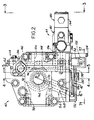
- Pump system 40 in accordance with a presently preferred embodiment of the invention, comprises a unitary assembly illustrated in greater detail in FIGS. 2-8.
- a case 60 is mounted to one face of a valve block 62 and defines an internal pump cavity 64.
- a pump drive shaft 66 is mounted within cavity 64 by bearings 68 (FIG. 4) for rotation about its axis.
- a cylinder block 70 is coupled by the splines 72 for co-rotation with shaft 66 about the shaft axis.
- a plurality of cylinder bores 76 are disposed in cylinder block 70 in a circumferential array about the shaft axis of rotation and slidably receive a corresponding plurality of pistons 74.
- a shoe 78 is pivotally carried at the base of each piston 74 and is captured by a ring 80 for sliding engagement with the face 82 of a swash plate or yoke 84.
- Yoke 84 is mounted on a saddle bearing 86 carried by case 60 for movement about an axis perpendicular to the axis of shaft 66.
- a valve plate 88 is mounted on valve block 62 within cavity 64 and has a face slidably engaged by cylinder block 70, cylinder block 70 being urged by the spring 90 into sliding engagement with valve plate 88.
- Valve plate 88 has a pair of kidney-shaped slots or ports 92,94 (in phantom in FIG. 2) that register with cylinder end openings 96 (FIG. 4) in cylinder block 70 as the latter rotates for sequentially connecting the cylinder block cavities to fluid inlet and outlet ports 98,100 (phantom in FIGS. 2 and 3) in valve block 62.
- An actuator 102 (FIG. 5) is mounted on valve block 62 within cavity 64 radially outwardly of cylinder block 70 (FIG. 4).
- Actuator 102 has a piston 104 that engages yoke 84 for pivoting yoke 84 within saddle bearing 86 (FIG. 4). Actuator 102 receives hydraulic fluid through ports 106 (FIGS. 2, 5 and 8) from control valve 44 (FIGS. 1-3 and 8-9) mounted on valve block 62 externally of cavity 64.
- a yoke-biasing actuator 110 (FIG. 5) is carried by valve block 62 within cavity 64 and has a piston 112 that engages yoke 84 diametrically opposite actuator 102.
- Actuator 110 is coupled by ports 114 (FIGS. 2-3 and 5) to pump output port 100.
- a collar 116 encircles piston 112 and is urged against a shoulder on cylinder 112 by a coil spring 118 captured between collar 116 and the opposing face of valve block 62.
- a bolt 120 is threaded into valve block 62 and is slidably engaged by a slot 122 in the periphery collar 116 for preventing rotation of collar 116 about the axis of piston 112 and actuator 110.
- Actuator 110 biases yoke 84 to a maximum displacement position illustrated in the drawings, and displacement is reduced as a function of operation of actuator 102.
- pump 40 is of generally conventional construction. Position of yoke 84 is controlled by actuator 102 and valve 44 acting against the force of actuator 110 and spring 118. Angle of yoke 84 in turn controls stroke of pistons 74 within cylinder block 70, and thus controls total pump displacement and pump output flow and pressure.
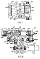
- pump controller 42 takes the form of a microprocessor-based controller (FIGS. 9, 11 and 12A-12E) embodied in a printed circuitboard assembly 130 (FIGS. 2 and 7) mounted externally of valve block 62.
- a cover 132 is fastened by bolts 134 to valve block 62 to define a sealed cavity containing circuitboard 130 and other electronics to be described.
- Yoke position sensor 50 (FIGS. 1, 3, 5 and 9), which may comprise an LVDT or a linear potentiometer for example, has a cylindrical body 135 captured within a counterbore 137 in valve block 62 between a snap ring 139 and a spring washer 141.
- a rod 138 extends from one end of sensor body 135 into cavity 64 and is coupled therewithin to collar 116 on biasing actuator 110.
- Leads 140 (FIGS. 3, 5 and 7) extend from the opposing end of sensor body 135 through a sealed passage 142 in valve block 62, and emerge beneath cover 132 (FIG. 7) for connection to the pump control electronics.
- a cover 136 (FIGS. 2 and 5) is removably mounted on the external face of valve block 62 over counterbore 137 to provide access to sensor 50.
- Sensor 50 thus provides a signal D (FIGS. 9, 11 and 12C) to pump control electronics 42 indicative of position of yoke 84, and thereby indicative of pump displacement.
- Connectors 133 (FIGS. 2-4 and 7) on cover 132 provide for connection of controller 42 to bus 36 (FIG. 1).
- Pressure sensor 52 (FIGS. 1-3, 7 and 9) is mounted beneath cover 132 and has a sensing tip 146 threaded into valve block 62 to receive hydraulic fluid from output port 100 through the fluid passage 148 (FIGS. 2 and 3). Sensor 52 is connected by leads 152 (FIG. 7) to pump control electronics 42 beneath cover 132 for providing thereto an electrical signal P indicative of pump output fluid pressure. Provision is also made for mounting a second pressure sensor 154 (FIG. 7) beneath cover 132 and connecting corresponding leads 156 to the pump control electronics. A port 158 (FIG. 3) on valve block 62 provides for connection of sensor 154 to external pressure. For example, sensor 154 may be connected to load pressure where it is desired to provide electronic differential pressure control (load sensing) through the pump control electronics.
- Pump speed sensor 54 (FIGS. 1, 2, 4, 6 and 9) comprises a toothed wheel or sprocket 162 of ferromagnetic construction press fitted onto the splined end of pump drive shaft 66 for coaxial co-rotation therewith. It will be noted in FIGS. 4 and 6 that sprocket 162 is positioned within a central cavity 166 in valve block 62.
- a magnetic sensor 168 (FIGS. 2, 4 and 6) comprises a permanent magnet, pole piece and coil assembly 170 that extends outwardly through a passage 171 in valve block 62 from a position radially adjacent to the teeth of sprocket 162. The magnetic sensor is held against a shoulder 173 within valve block passage by a spacer collar 174 (FIG.
- Control valve 44 is illustrated in greater detail in FIGS. 8 and 10, and includes a solenoid valve 180 mounted on a combined pressure limiter and load sensing valve 182, which in turn is mounted externally of valve block 62 (FIG. 2).
- Solenoid valve 180 includes a solenoid coil 184 having leads 186 (FIGS. 2 and 7) connected through passages in pressure limiter and load sensing valve 182 (FIG. 8), and through passages 190 in valve block 62 (FIGS. 2 and 7), to emerge beneath cover 132 for connection to control electronics 42.
- valve 180 has a fluid input 200 (FIG. 8) connected to output port 100 (FIG. 2) through passages 202 in pressure limiter/load sensing valve 182 and through passage 148 in valve block 62 (FIG. 2).
- the presser limiter is inactive (FIG. 8)
- the fluid outlet 204 of valve 180 communicates with yoke actuator 102 (FIG. 5) through a check valve 207 (FIGS. 8 and 10) in pressure limiter/load sensing valve 182, and through passages 106 (FIGS.
- Check valve 207 (FIGS. 8 and 10) allows outlet 204 to bypass the load sensing valve to port 106B when off-stroking the pump. To on-stroke the pump, the fluid must pass through the load sensing spool 209.
- Pressure limiter and load sensing valve 182 has a common manifold 240.
- a pressure responsive spool 242 is slidable within a bore 244 and has lands 246 for controlling flow of fluid at control pressure through passage 106 to displacement-control actuator 102 (FIG. 5).
- spool 242 When the pump output pressure is below the limit value, spool 242 is urged by coil spring 212 to a position against abutment 254. This allows fluid in control actuator 102 to vent to tank port 260 through load sensing spool 209 and electrohydraulic valve spool 192 in valve bodies 182 and 194.
- Coil spring 212 is adjustably captured between seat 248 that engages the inward end of spool 242 and a second seat 250 that is engaged by pressure limit adjustment screw 252.
- a piston 258 is slidable in the opposing end of spool 242 and engages abutment 254.
- Pump output pressure in manifold passage 202 is communicated to the inner end of piston 258 through spool passage 256.
- the pressure urges spool 242 to move in opposition to the force exerted by spring 212 when the pressure force exceeds the adjusted value of the spring force. This allows fluid to flow across land 246 to the displacement-control actuator 102. Since the area responsive to pump output pressure is that of the small piston 258 rather than that of spool 242, a smaller spring 212 than is conventional in the art can be used, thereby reducing the overall size of the pressure limiter and load sensing valve 182.
- Tank port 260 in manifold 240 communicates through passages (not shown) with internal pump case cavity 64 (FIG. 4), and opens into the cavity surrounding spring 212, seats 248, 250 and the cavity surrounding the spring-remote end of spool 242.
- the optimal hydromechanical load sensing valve 209 functions in a conventional manner. Pump discharge pressure acts on the left end of spoof 209 and load orifice down stream pressure is ported to the spring cavity at the right end of the load sensing spool 209. This spool maintains a constant differential pressure across the load orifice in spite of varying load pressure. This arrangement of spools provides the necessary functional priorities while minimizing the need for special hardware.
- the load sensing function can be implemented hydromechanically or through the electronic control previously described.
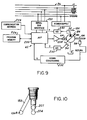
- Pump system 40 is illustrated functionally in FIG. 9 as comprising a microprocessor 220 having input and output ports respectively connected through a serial interface 222 to the COM, /COM and T/R conductors of bus 36.
- the COM and /COM lines comprise conventional differential transmission lines, and the T/R line indicates transmission or reception mode.
- Pump control microprocessor 220 receives a communication address input from an address selection module 224, which may comprise DIP switches or the like for selectively setting pump controller address, or electronic memory for receiving and storing an address command from master controller 34 (FIG. 1) on initial start-up.
- Microprocessor 220 is also connected to a memory 226 having stored therein the various pump control programs or algorithms.
- a power amplifier 228 feeds pulse width modulated control signals from microprocessor 220 to control solenoid 184 (FIG. 8) of valve 180 for controlling yoke position, and thereby controlling output of pump 46.
- Sensor 50 is responsive to yoke position as previously described, and is connected through an A/D converter 230 for providing signal D to microprocessor 220 indicative of yoke position.
- sensor 54 is operatively coupled to pump drive shaft 66 as previously described to provide a signal N through signal conditioning circuitry 232 indicative of pump shaft speed.
- Pressure sensor 52 provides pressure signal P to microprocessor 220 through A/D converter 230.
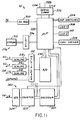
- FIG. 11 is a more detailed functional block diagram of the control electronics in the system illustrated generally in FIG. 9.
- Microprocessor 220 and the remainder of the control circuitry receive power from bus 36 through a five volt regulator 300.
- Memory 226, including an EPROM 302 is connected to microprocessor 220 through an associated address decoder and latch 306.
- LEDs 308, 310 are connected to the microprocessor for indicating pendency of communication through serial communications interface 222 and signal bus 36 (FIGS. 1 and 9).
- the signal outputs of displacement sensor 50 and pressure sensors 52, 54 are connected to the signal inputs of a multiplexer 312 through associated scaling circuits 314, 316, 318 respectively.
- Multiplexer 312 also has a spare signal input line.
- the signal output of multiplexer 312 is connected through a/d converter 230 to data inputs of microprocessor 220.
- An address decoder 320 receives an output from microprocessor 220, and is connected both to the selection control inputs of multiplexer 312 and to the data input of a counter 322.
- Counter 322 receives an enabling input from microprocessor 220 and a clock input from speed sensor 54 through a one-shot 324.
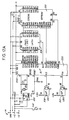
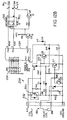
- FIGS. 12A-12E together comprise an electrical schematic diagram of control electronics 42.
- a major portion of electronics 42 is similar to the valve control electronics disclosed in U.S. Patent No. 4,757,747 referenced hereinabove.
- Valve driver 228 in accordance with one aspect of the present invention is illustrated in detail in FIG. 12B, and the electronics for measuring pump speed in accordance with another aspect of the invention is illustrated in FIG. 12E.
- Valve driver 228 (FIG. 12B) includes an N-FET 330 having primary current-conducting source and drain electrodes connected in series with coil 184 of valve 180 and a current sensing resistor R43 between a voltage supply bus 332 and ground.
- the gate of N-FET 330 is connected to a transistor switch Q7, Q8 that receives a switch control input from microprocessor 220 through a series capacitor C17.
- the high side of coil 184 at the drain of N-FET 330 is also connected to the input of switch Q7, Q8 at the base of transistor Q7 through the series combination of resistors R41, R44 and a zener diode D12.
- Current sensing resistor R43 is connected across the base of a transistor Q8 that has a collector connected to the base of transistor Q7.
- the base of transistor Q7, forming the input of transistor switch Q7, Q8, is also connected through resistor R44 and a diode D19 to the switch control input from microprocessor 220.
- the switch control input to valve driver 228 from microprocessor 220 preferably comprises a pulse width modulated signal having a constant frequency, and having a duty cycle that varies in proportion to desired flow at valve 180.
- Positive transition of the switch control input signal drives the base of Q7 high for a time determined by capacitor C17 and resistor R45, which thus form a one-shot having an output pulse duration on the order of sixty microseconds, for example.
- This pulse turns on transistor Q7, turns off transistor Q8, and thus drives the gate of N-FET 330 through resistor R40 and diode D11, causing the N-FET to saturate and pass current to coil 184 and resistor R43.
- the voltage drop across coil 184 and resistor R43 is sufficient to maintain the high signal level at the base of transistor Q7 through the feedback path R41, D12, R44 and resistor R45 across the base of transistor Q7.
- the combination of the input one-shot capacitor C17 and feedback components R41, R44, D12 thus form a latch for maintaining transistor switch Q7, Q8. in the set condition in which N-FET 330 passes current to valve coil 184.
- Resistor R40 and capacitor C18 are selected to establish a low-frequency cutoff for valve driver 228, such as at 100 Hz for example.
- valve coil 184 If the high side of valve coil 184 is shorted to the low side or to ground at the time of the positive switch control input signal transition, the voltage drop across the coil will be insufficient to maintain transistor Q7 in the on condition through resistors R41, R44 and diode D12, so that switch Q7, Q8 will reset immediately upon termination of the C17 one-shot pulse. This short pulse is insufficient to cause destruction of N-FET 330. If N-FET 330 is turned on when the short circuit occurs, switch Q7, Q8 will turn off N-FET 330 to prevent damage.
- N-FET 330 If an overload is imposed on N-FET 330 and too much current is drawn in other than a condition that short circuits coil 184, voltage drop across resistor R43 will be above the threshold at the base of transistor Q8. Transistor Q8 will thus turn on and short circuit the base of transistor Q7, resetting transistor switch Q7, Q8 and turning off N-FET 330.
- Coil drive circuit 228 thus employs an N-FET 330 that has approximately one-half of the series resistance than do P-FETs conventionally employed in such applications, thereby minimizing heat dissipation. Further, the described circuitry for sensing conditions at valve coil 184 and terminating valve current protects N-FET 330 against excessive heat and damage.
- counter 322 of speed sensing circuit 340 includes an up/down counter 342 that has a clock input connected to coil 172 of sensor 54 (FIGS. 2 and 6) through one-shot 324.
- the data inputs of counter 342 are connected to the data outputs of a latch 344, which in turn has inputs connected to microprocessor 220 (FIGS. 11 and 12A).
- the control inputs of latch 344 and counter 342 are connected to address decoder 320, which in turn is controlled by associated outputs of microprocessor 220.
- speed sensing circuitry 340 provides an output to the P3.2 (FIG. 12E) input of microprocessor 220 that indicates total time interval over a preselected number of speed signal cycles from coil 172. That is, microprocessor 220 determines the number of tooth intervals over which the speed measurement cycle is to be measured, and this number (incremented by one) is placed on the associated microprocessor output port and stored in latch 344 through enablement of address decoder 320. For example, if the speed measurement is to be performed over eight inter-tooth intervals, the number "9" (corresponding to the total number of teeth involved in eight tooth intervals) is loaded into latch 344.
- microprocessor 220 then enables counter operation through decoder 320, first to load the preselected count from latch 344 into counter 342, and then to down-count the counter as a function of the clock signals received from one-shot 324 upon occurrence of each sprocket tooth.
- the first tooth passing sensor 54 after enabling counter 342 causes the P3.2 input of microprocessor 220 to go high.
- microprocessor input P3.2 goes low.
- Microprocessor 220 is programmed such that its internal timer increments each microsecond that the P3.2 input is high. Since turning the timer on and off is not controlled by software, other interrupts have no effect upon timer accuracy.
- the number of teeth or pulses over which shaft speed is to be measured is easily and selectively adjustable at the microprocessor.
- the accuracy of the measurement itself corresponds to the period of the microprocessor clock (FIG. 12A), typically one microsecond.
- the timer interrupt used for measuring time between the teeth does not have to be serviced immediately, and may also be relatively simple.
- the speed sensing interrupt does not affect the performance of the other interrupts, such as the pulse width modulation and serial communication interrupts, and the other interrupts do not affect the speed sensing interrupt.
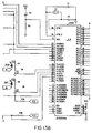
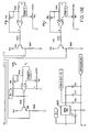
- FIGS. 13A-13E together comprise an electrical schematic diagram of a modified pump controller, FIGS. 13A and 13B being interconnected along the lines A-B in each figure, FIGS. 13B and 13C being interconnected along the lines B-C in each figure, FIGS. 13C and 13E being interconnected along the lines C-E in each figure, and FIGS. 13D and 13E being interconnected along the lines D-E in each figure.
- Elements corresponding to those hereinabove discussed in detail in conjunction with FIGS. 11 and 12A-E are identified by correspondingly identical reference numerals. Only differences between the controllers will be discussed in detail.
- Microprocessor 220 in the controller of FIGS. 13A-13B is sufficiently fast and powerful that multiplexer 312 (FIG. 12D) is eliminated, and the signal conditioning circuits 314-318 (FIG. 13E) are connected directly to corresponding ports (FIG. 13B) of the microprocessor.
- one-shot 324 (FIG. 13D) is connected directly to a corresponding port (FIG. 13B) of the microprocessor, and the separate speed computation electronics of FIG. 12E is eliminated.
- a diode D9 (FIG. 13D) and a capacitor C11 (FIG.
- FIG. 13E are connected to the power input of voltage regulator 400 for maintaining power at the controller board for up to two milliseconds after loss of supply voltage, which allows the microprocessor ample time to turn off the output drivers (FIG. 13A) to the valve coils.
- An EEPROM 402 (FIG. 13D) is connected to microprocessor 220 (FIG. 13B) and stores erasable programming, including the address associated with the pump controller, thereby eliminating the address switches 224 (FIGS. 11 and 12B).
- Two coil drivers 410, 412 are provided for pulse width modulating a pair of coils on a proportional solenoid flow control valve or the like. Since the power MOSFET in each driver is between the coil and the supply voltage, as in driver 228 (FIG. 12B), the associated coil cannot be energized unless the MOSFET is turned on. (Circuits using low side drivers can inadvertently be turned on if one side of the coil is shorted to ground.) Likewise, as hereinabove discussed in conjunction with driver 228, the N-channel MOSFETs Q4 and Q7 exhibit a lower "on" resistance than do P-channel MOSFETs, thus minimizing the heat dissipated by the drivers.
- the gate voltage for an N-channel MOSFET must exceed the supply voltage to turn the MOSFET on.
- drivers 410 when transistor Q5 is turned on by the microprocessor, the gate voltage at MOSFET Q4 drops to ground and the voltage at TERM7 also drops to ground. Supply voltage is connected across capacitors C5, and the capacitor charges to supply potential.
- transistor Q5 is turned off by the microprocessor, the voltage at the gate of MOSFET Q4 turns the MOSFET on.
- the gate voltage of MOSFET Q4 increases proportionally due to capacitor C5. This voltage is limited by zener diode D1 to protect MOSFET Q4.
- Driver 412 operates in the same manner. If the pulsed output from the microprocessor should stop for any reason, pull-up resistors R35 and R37 will turn off associated transistors Q5 and Q9, and thereby turn off the MOSFET drivers Q4 and Q7.
- a current overload, sensor 414 senses excessive current being drawn by one or both of the valve coils, which could damage drivers Q4 and Q7 or cause the supply voltage to drop sufficiently for the microprocessor to malfunction.
- the sum of the currents through drivers Q4 and Q7 passes through the sensing resistor R1 connected between the supply voltage and the coils.
- the voltage drop across resistor R1 correspondingly increases up to a level that turns on threshold detector Q2.
- detector Q2 turns on MOSFET Q3
- an interrupt is generated to microprocessor 220 (FIG. 13B).
- the microprocessor then turns off the coil drivers and advises the operator of a problem.
Landscapes
- Engineering & Computer Science (AREA)
- Physics & Mathematics (AREA)
- Computer Hardware Design (AREA)
- Mechanical Engineering (AREA)
- General Engineering & Computer Science (AREA)
- Fluid Mechanics (AREA)
- General Physics & Mathematics (AREA)
- Automation & Control Theory (AREA)
- Control Of Positive-Displacement Pumps (AREA)
- Reciprocating Pumps (AREA)
Claims (30)
- Machine hydraulique tournante à déplacement variable comprenant :un boítier (60, 62) qui comprend un carter (60) et un bloc de vanne (62) montés assemblés l'un à l'autre de manière à inclure une cavité interne (64) dans laquelle sont positionnés un arbre (66), un moyen de cylindre (70), un moyen de piston (74) et un moyen de modification de déplacement (48),ledit arbre (66) étant monté à l'intérieur dudit boítier (60, 62) pour tourner autour d'un axe d'arbre;ledit moyen de cylindre (70) comportant une cavité de cylindre (76) à l'intérieur dudit boítier ;ledit moyen de piston (74) étant disposé dans ladite cavité de cylindre, soit ledit moyen de piston soit ledit moyen de cylindre étant couplé audit arbre;un moyen de vanne (62, 88) incluant un plateau de distribution (88) et ledit bloc de vanne (62) formant des orifices d'entrée et de sortie de fluide (92/98, 94/100) dans ledit boítier et un moyen (96) pour connecter sélectivement ladite cavité (76) auxdits orifices d'entrée et de sortie de fluide (92/98, 94/100);ledit moyen de modification de déplacement (48) étant couplé à soit ledit moyen de piston soit ledit moyen de cylindre à l'intérieur dudit boítier pour modifier le déplacement dudit moyen de piston (74) dans ladite cavité de cylindre lorsque ledit arbre (66) tourne autour dudit axe ; etun moyen de capteur (50, 52, 54) pour détecter des conditions de fonctionnement de ladite machine et pour produire des signaux de capteur électronique en fonction de celles-ci ;un moyen de commande électronique basé sur microprocesseur (42) incluant un moyen (220) pour recevoir et stocker lesdits signaux de capteurs provenant dudit moyen de capteur (50, 52, 54) et des signaux électroniques de commande provenant d'une source externe (34); etun moyen de commande de déplacement (44) sensible auxdits signaux de commande provenant dudit moyen de commande électronique basé sur microprocesseur (42) pour commander la position dudit moyen de modification de déplacement (48) dans ledit boítier (60,62),
caractérisée en ce que :tant le moyen de commande électronique (42), qui inclut le moyen (220) pour recevoir et stocker des signaux électroniques de commande, que le moyen de capteur (50, 52, 54) sont montés sur des parois dudit bloc de vanne (62) de manière à former un assemblage d'un seul tenant avec la machine. - Machine selon la revendication 1,
dans laquelle ledit moyen de capteur inclut un capteur de déplacement (50) couplé audit moyen de modification de déplacement (48) pour produire un signal de déplacement. - Machine selon la revendication 1 ou 2,
dans laquelle ledit moyen de commande électronique (42) inclut un moyen (220) pour comparer ledit signal de déplacement auxdits signaux de commande pour générer des signaux d'erreur en fonction d'une différence entre eux, ledit moyen de commande de déplacement (44) étant sensible auxdits signaux d'erreur pour commander la position dudit moyen de modification de déplacement (48). - Machine salon la revendication 3,
dans laquelle ledit moyen de modification de déplacement (48) comprend une culasse (84) comportant une surface (82) mise en contact coulissant avec ledit moyen de piston (74) ; et
dans laquelle ledit moyen de commande de déplacement (44) sensible auxdits signaux d'erreur comprend un actionneur de commande de déplacement (102) couplé à ladite culasse (84) et une vanne de commande de déplacement (180) comportant une entrée (200) couplée à l'un (100) desdits orifices de fluide (92/98, 941100), une sortie (204) couplée audit actionneur (102), un élément de vanne positionnable de façon variable (192) pour commander un écoulement de fluide depuis ladite entrée (200) jusqu'à ladite sortie (204), une armature (196) couplée audit élément de vanne (192) et un stator (184) sensible auxdits signaux d'erreur. - Machine selon la revendication 3 ou 4,
dans laquelle ledit moyen de génération de signal (220) inclut un moyen de mémoire (226) pour stocker des programmes prédéterminés pour commander la position dudit moyen de modification de déplacement (48) en tant que fonction différente desdits signaux de commande et d'erreur, et
dans laquelle ledit moyen de commande basé sur microprocesseur (42) inclut un moyen sensible à des signaux provenant d'une source externe (34) pour réaliser une sélection entre lesdits programmes prédéterminés. - Machine selon l'une quelconque des revendications 1 à 5,
dans laquelle ledit moyen de commande basé sur microprocesseur (42) inclut en outre un moyen pour établir une adresse associée audit moyen de commande en vue de communications avec la source externe (34). - Machine selon la revendication 1,
dans laquelle un moyen de poussée (110) est monté sur ledit bloc de vanne (62) à l'intérieur de ladite cavité (64) et coopère avec ledit moyen de modification de déplacement (48) pour pousser celui-ci jusqu'à une position de déplacement présélectionnée, et des éléments (116, 138) dudit capteur (50) sont couplés audit moyen de poussée (110) pour produire un signal de déplacement. - Machine selon la revendication 7,
dans laquelle ledit moyen de poussée comprend un actionneur hydraulique (110) comportant une entrée (114) couplée par l'intermédiaire dudit bloc de vanne (62) à l'un (100) desdits orifices, un piston (112) coopérant avec ledit moyen de modification de déplacement (48), un collier (116) sur ledit piston et un ressort hélicoïdal (118) entourant ledit piston et ledit bloc de vanne (62), ledit collier (116) étant l'un desdits éléments (116, 138) pour coupler ledit moyen de poussée audit capteur (50). - Machine selon la revendication 8,
comprenant en outre un moyen (122) pour empêcher la rotation dudit collier (116) par rapport audit bloc (62). - Machine selon l'une quelconque des revendications 1 à 9,
dans laquelle ledit moyen de capteur comprend en outre un capteur de pression (52) couplé à l'un (100) desdits orifices (92/98, 94/100) pour produire un signal électronique en fonction d'une pression de fluide au niveau dudit orifice (100), et
dans laquelle ledit moyen de commande basé sur microprocesseur (42) inclut un moyen (220, 230) sensible audit signal de pression pour commander le fonctionnement de ladite machine. - Machine selon l'une quelconque des revendications 1 à 10,
dans laquelle ledit moyen de capteur comprend un capteur de vitesse (54) comportant un élément (162) couplé audit arbre (66) et un élément stationnaire (168) pour produire un signal électronique en fonction de la vitesse de rotation dudit arbre et dans laquelle ledit moyen de commande basé sur microprocesseur (42) inclut un moyen (220, 232) sensible audit signal de vitesse pour commander le fonctionnement de ladite machine. - Machine selon la revendication 10 ou 11,
dans laquelle ledit élément de capteur de vitesse (126) est un rotor (62) à l'intérieur d'une cavité (166) du bloc de vanne (62) et ledit élément stationnaire (168) est un stator à l'intérieur d'un passage (171) ménagé dans ledit bloc de vanne (62) radialement adjacent audit rotor (162). - Machine selon la revendication 12,
dans laquelle ledit rotor comprend une roue dentée (162) de construction ferromagnétique, et
dans laquelle ledit stator comprend un capteur inductif (168). - Machine selon la revendication 12 ou 13,
dans laquelle ledit moyen de commande basé sur microprocesseur (42) comprend un assemblage de carte de circuit imprimé (130) monté de façon externe par rapport audit bloc de vanne (62), et un couvercle (132) qui est monté sur ledit bloc de vanne (62). - Machine selon la revendication 14,
dans laquelle ledit stator (168) dudit capteur de vitesse (54) et ledit capteur de pression (52) sont supportés par une paroi dudit bloc de vanne (62) qui, en utilisation normale de la machine, est agencée au-dessous dudit couvercle (132), tandis que ledit capteur de déplacement (50) est espacé dudit couvercle (132), des passages (148, 190) traversant ledit bloc de vanne (62) étant prévus pour connecter électriquement ledit capteur de déplacement (50) audit moyen de commande basé sur microprocesseur (42) et pour coupler du point de vue du fluide ledit capteur de pression (52) audit un (100) desdits orifices. - Machine selon l'une quelconque des revendications 1 à 15,
dans laquelle ledit moyen de commande de déplacement (44) comprend une vanne électrohydraulique (180) montée sur ledit bloc de vanne (62), ladite vanne (180) comportant une sortie (204) et une entrée (200) couplée à l'un (100) desdits orifices, un élément de vanne positionnable de façon variable (190) pour commander l'écoulement d'un fluide depuis ladite entrée jusqu'à ladite sortie, une armature (196) couplée audit élément de vanne (192) et un stator (184) sensible audit moyen de commande électronique (242), un passage (190) traversant ledit bloc de vanne (62) étant prévu pour connecter électriquement ledit moyen de commande basé sur microprocesseur (42) audit stator (184) - Machine selon la revendication 16,
dans laquelle ladite machine est une pompe à déplacement variable (46), et ledit un (100) desdits orifices est l'orifice de sortie (100) de ladite pompe (46). - Machine selon la revendication 16 ou 17,
dans laquelle ledit moyen de commande de déplacement (44) comprend en outre un moyen de limitation de pression (182) qui régie l'application d'une pression de commande depuis ladite vanne éloctrohydraulique (180) sur un actionneur (102) en fonction de la pression de sortie de pompe, ledit moyen de limitation de pression (182) comprenant un collecteur (240) comportant des passages (106, 202) pour recevoir un fluide à une pression de sortie de pompe et pour délivrer un fluide à ladite pression de commande audit actionneur (102), un tiroir de distribution (242) positionné de façon mobile dans ledit collecteur (240) muni d'un bord d'orifice (246) pour commander un écoulement de fluide au travers dudit passage de commande (106) et également depuis ledit actionneur (102) jusqu'à un réservoir, un ressort (212) à l'intérieur dudit collecteur (240) pour coopérer avec ledit tiroir de distribution (242) et pour pousser ledit tiroir de distribution en direction d'une position qui évacue ledit actionneur (102) dans un réservoir (260), une butée dans ledit collecteur (240) adjacente à une extrémité en opposition dudit tiroir de distribution (242), un piston (258) disposé de façon coulissante dans ledit tiroir de distribution (242) pour venir en appui contre ladite butée (254), et un passage axial (256) ménagé dans ledit tiroir de distribution (242) pour délivrer une pression de sortie sur une extrémité en opposition dudit piston (258) de manière à ouvrir le bord d'orifice de tiroir de distribution (246) à un passage de commande (106) lorsque la pression de sortie excède la valeur limite. - Machine selon l'une quelconque des revendications 16 à 18,
dans laquelle ledit stator (184) inclut un moyen de bobine électronique pour recevoir des signaux de commande de vanne et
dans laquelle ladite machine comprend en outre un moyen de commande de vanne électrique (228) incluant :un commutateur à l'état solide (330) comportant des électrodes de puissance pour appliquer sélectivement de l'énergie électrique sur ledit moyen de bobine de stator (184) et comportant une électrode de commande, un moyen (C17) pour appliquer un signal de commande de commutateur, un moyen de circuit de commutateur (Q7, Q8) sensible audit signal de commande de commutateur et couplé à ladite électrode de commande pour établir ledit moyen de circuit de commutateur et pour appliquer de l'énergie audit moyen de bobine en réponse audit signal de commande de commutateur et un moyen (R40, C18) sensible au courant traversant ledit moyen de bobine (184) pour remettre à l'état initial ledit moyen de circuit de commutateur (Q7, Q8) et pour arrêter l'application de l'énergie électrique sur ledit moyen de bobine indépendamment dudit signal de commande de commutateur. - Machine selon la revendication 19,
dans laquelle ledit moyen de réponse sensible au courant comprend un moyen (R41, R44, D12) sensible à une chute de tension aux bornes dudit moyen de bobine (184) pour maintenir dans l'état établi ledit moyen de circuit de commutateur (Q7, Q8). - Machine selon la revendication 19 ou 20,
dans laquelle ledit moyen sensible au courant (Q7, Q8) comprend en outre un moyen (R43) sensible à un courant excessif traversant ledit moyen de bobine (184) pour remettre à l'état initial ledit moyen de circuit de commutateur (Q7, Q8) de façon indépendante par rapport audit moyen sensible à la chute de tension et audit signal de commande de commutateur. - Machine selon l'une quelconque des revendications 19 à 21,
dans laquelle ledit moyen de circuit de commutateur (Q7, Q8) inclut un multivibrateur monostable (C17, R45) sensible à des transitions d'une polarité au niveau dudit signal de commande de commutateur pour établir ledit moyen de circuit de commutateur (Q7, Q8) et un moyen (DI9) sensible à des transitions au niveau dudit signal de commande de commutateur de polarité opposée pour remettre à l'état initial ledit moyen de circuit de commutateur. - Machine selon l'une quelconque des revendications 19 à 22,
dans laquelle ledit commutateur à l'état solide (330) comprend un N-FET. - Machine selon la revendication 23,
dans laquelle ledit N-FET est connecté entre une alimentation en tension (332) et une borne dudit moyen de bobine (184), ledit moyen de bobine comportant une seconde borne connectée à la masse. - Machine selon l'une quelconque des revendications 12 à 24,
dans laquelle ledit moyen sensible à la vitesse (340) inclut un moyen (320) pour initier un cycle de mesure de vitesse, un moyen (220, 322) pour mesurer une durée temporelle sur un nombre présélectionné de cycles de signaux provenant dudit stator, et un moyen pour déterminer la vitesse de rotation de l'arbre en fonction de ladite durée temporelle. - Machine selon l'une quelconque des revendications 12 à 24,
dans laquelle ledit moyen de commande comprend un microprocesseur (220), et dans laquelle ledit moyen sensible à la vitesse inclut un moyen (320) sensible audit microprocesseur pour initier un cycle de mesure de vitesse et un moyen pour mesurer une durée temporelle sur un nombre présélectionné de cycles de signaux de stator, ledit microprocesseur (220) étant sensible à ladite durée temporelle pour déterminer ladite vitesse de rotation de l'arbre. - Machine selon la revendication 26,
dans laquelle ledit moyen sensible à la vitesse (340) inclut en outre un moyen (320, 344) sensible audit microprocesseur (220) pour commander de façon variable ledit nombre présélectionné de cycles. - Machine selon la revendication 26 ou 27,
dans laquelle ledit moyen de mesure de durée (322) comprend un compteur (342) comportant une entrée de comptage sensible auxdits cycles de signaux et une entrée de validation sensible audit moyen d'initiation de mesure. - Machine selon la revendication 28,
dans laquelle ledit compteur (342) comprend un décompteur comportant des entrées de données pour précharger une valeur de comptage correspondant audit nombre présélectionné de cycles de signaux. - Machine selon la revendication 29,
dans laquelle ledit moyen de mesure de durée (322) comprend en outre une bascule (344) comportant une entrée couplée audit microprocesseur (220) pour recevoir et stocker ladite valeur de comptage et une sortie couplée auxdites entrées de données de compteur ; et dans laquelle ledit moyen d'initiation de cycle inclut un moyen sensible audit microprocesseur pour charger sélectivement ladite valeur de comptage provenant de ladite bascule dans ledit compteur.
Applications Claiming Priority (2)
| Application Number | Priority Date | Filing Date | Title |
|---|---|---|---|
| US412211 | 1989-09-25 | ||
| US07/412,211 US5073091A (en) | 1989-09-25 | 1989-09-25 | Power transmission |
Publications (4)
| Publication Number | Publication Date |
|---|---|
| EP0419984A2 EP0419984A2 (fr) | 1991-04-03 |
| EP0419984A3 EP0419984A3 (en) | 1992-03-04 |
| EP0419984B1 EP0419984B1 (fr) | 1995-11-08 |
| EP0419984B2 true EP0419984B2 (fr) | 2000-05-03 |
Family
ID=23632061
Family Applications (1)
| Application Number | Title | Priority Date | Filing Date |
|---|---|---|---|
| EP90117815A Expired - Lifetime EP0419984B2 (fr) | 1989-09-25 | 1990-09-15 | Réglage électro-hydraulique pour une machine hydraulique |
Country Status (6)
| Country | Link |
|---|---|
| US (1) | US5073091A (fr) |
| EP (1) | EP0419984B2 (fr) |
| JP (1) | JP3411567B2 (fr) |
| CN (1) | CN1025881C (fr) |
| AU (1) | AU639924B2 (fr) |
| DE (1) | DE69023448T3 (fr) |
Families Citing this family (66)
| Publication number | Priority date | Publication date | Assignee | Title |
|---|---|---|---|---|
| US5295795A (en) * | 1991-04-12 | 1994-03-22 | Hitachi Construction Machinery Co., Ltd. | Hydraulic drive system for construction machine |
| US5220225A (en) * | 1992-06-17 | 1993-06-15 | Vickers, Incorporated | Integrated electric motor driven inline hydraulic apparatus |
| DE4237971B4 (de) † | 1992-11-11 | 2004-05-06 | Unaxis Deutschland Holding Gmbh | Vakuumpumpe mit Wandler |
| DE4239145C1 (de) * | 1992-11-20 | 1994-03-17 | Hydromatik Gmbh | Meßeinrichtung zum Erfassen der Verdrängungsvolumen-Einstellung von Axialkolbenmaschinen |
| DE4315165A1 (de) * | 1993-05-07 | 1994-11-10 | Leybold Ag | Vakuumpumpe |
| US5515829A (en) * | 1994-05-20 | 1996-05-14 | Caterpillar Inc. | Variable-displacement actuating fluid pump for a HEUI fuel system |
| US5666806A (en) * | 1995-07-05 | 1997-09-16 | Caterpillar Inc. | Control system for a hydraulic cylinder and method |
| NL1001814C2 (nl) * | 1995-12-04 | 1997-06-10 | Terberg Machines | Hydraulisch systeem. |
| DE19606747A1 (de) * | 1996-02-23 | 1997-08-28 | Scharco Elektronik Gmbh & Co K | Anordnung zur Steuerung von Anzeige- und/oder Stellgeräten für den industriellen Einsatz |
| US5933795A (en) * | 1996-03-19 | 1999-08-03 | Sauer Inc. | Speed sensing device |
| US5884894A (en) * | 1996-08-20 | 1999-03-23 | Valtek, Inc. | Inner-loop valve spool positioning control apparatus |
| US5778671A (en) * | 1996-09-13 | 1998-07-14 | Vickers, Inc. | Electrohydraulic system and apparatus with bidirectional electric-motor/hydraulic-pump unit |
| US6203283B1 (en) * | 1999-02-26 | 2001-03-20 | Sauer Inc. | Single piece yoke stroking device for bent axis type hydraulic pumps and variable motors |
| JP4321788B2 (ja) * | 1999-03-31 | 2009-08-26 | 株式会社 神崎高級工機製作所 | 作業車両における変速制御装置 |
| US6216456B1 (en) | 1999-11-15 | 2001-04-17 | Caterpillar Inc. | Load sensing hydraulic control system for variable displacement pump |
| US6302654B1 (en) * | 2000-02-29 | 2001-10-16 | Copeland Corporation | Compressor with control and protection system |
| DE10030147C1 (de) | 2000-06-20 | 2002-06-06 | Brueninghaus Hydromatik Gmbh | Axialkolbenmaschine |
| DE10037927C2 (de) * | 2000-08-03 | 2002-11-14 | Sauer Danfoss Neumuenster Gmbh | Hydromotor |
| US6547531B1 (en) * | 2002-01-16 | 2003-04-15 | Terry L. Cumbo | Variable-displacement axial piston pump |
| US20060177317A1 (en) * | 2002-04-05 | 2006-08-10 | Thompson David J | Direct connection manifold for reciprocating piston pump |
| GB0216745D0 (en) * | 2002-07-18 | 2002-08-28 | Univ Cardiff | Sensor |
| DE60234828D1 (de) * | 2002-09-03 | 2010-02-04 | Futronic Gmbh | Modulares Steuerungssystem für eine Glasformmaschine |
| US7086225B2 (en) * | 2004-02-11 | 2006-08-08 | Haldex Hydraulics Corporation | Control valve supply for rotary hydraulic machine |
| US7380490B2 (en) * | 2004-02-11 | 2008-06-03 | Haldex Hydraulics Corporation | Housing for rotary hydraulic machines |
| US7412842B2 (en) | 2004-04-27 | 2008-08-19 | Emerson Climate Technologies, Inc. | Compressor diagnostic and protection system |
| JP4542819B2 (ja) * | 2004-05-21 | 2010-09-15 | 株式会社小松製作所 | 油圧機械、油圧機械の健康状態を監視するためのシステム及び方法 |
| JP4214965B2 (ja) * | 2004-07-22 | 2009-01-28 | 株式会社デンソー | 蒸発燃料処理装置の漏れ検出装置 |
| US7275377B2 (en) | 2004-08-11 | 2007-10-02 | Lawrence Kates | Method and apparatus for monitoring refrigerant-cycle systems |
| CN1670402A (zh) * | 2005-02-06 | 2005-09-21 | 曾义波 | 自循环泵式动力传递器 |
| US7114432B1 (en) | 2005-02-09 | 2006-10-03 | Sauer-Danfoss Inc. | Torque limiting device for hydraulic piston pump |
| GB0613662D0 (en) * | 2006-07-10 | 2006-08-16 | Rotork Controls | Improvements to valve actuators |
| US8590325B2 (en) | 2006-07-19 | 2013-11-26 | Emerson Climate Technologies, Inc. | Protection and diagnostic module for a refrigeration system |
| US20080216494A1 (en) | 2006-09-07 | 2008-09-11 | Pham Hung M | Compressor data module |
| US7854596B2 (en) * | 2007-01-24 | 2010-12-21 | Johnson Controls Technology Company | System and method of operation of multiple screw compressors with continuously variable speed to provide noise cancellation |
| US20090037142A1 (en) | 2007-07-30 | 2009-02-05 | Lawrence Kates | Portable method and apparatus for monitoring refrigerant-cycle systems |
| US20090053072A1 (en) * | 2007-08-21 | 2009-02-26 | Justin Borgstadt | Integrated "One Pump" Control of Pumping Equipment |
| US8393169B2 (en) | 2007-09-19 | 2013-03-12 | Emerson Climate Technologies, Inc. | Refrigeration monitoring system and method |
| US8160827B2 (en) | 2007-11-02 | 2012-04-17 | Emerson Climate Technologies, Inc. | Compressor sensor module |
| US9140728B2 (en) | 2007-11-02 | 2015-09-22 | Emerson Climate Technologies, Inc. | Compressor sensor module |
| SE533414C2 (sv) * | 2008-09-17 | 2010-09-21 | Parker Hannifin Ab | Oklägessensor för en hydraulisk anordning |
| DE102012202162A1 (de) * | 2011-02-23 | 2012-08-23 | Schaeffler Technologies AG & Co. KG | Hydraulische Einrichtung zur Betätigung einer Kupplung |
| EP2681497A4 (fr) | 2011-02-28 | 2017-05-31 | Emerson Electric Co. | Solutions de contrôle et de diagnostic d'un système hvac destinées à des habitations |
| US8924012B2 (en) | 2012-01-06 | 2014-12-30 | Marvel Tech Inc. | Electro-hydraulic interactive double feedback loop |
| US8964338B2 (en) | 2012-01-11 | 2015-02-24 | Emerson Climate Technologies, Inc. | System and method for compressor motor protection |
| US9480177B2 (en) | 2012-07-27 | 2016-10-25 | Emerson Climate Technologies, Inc. | Compressor protection module |
| DE102012214385A1 (de) * | 2012-08-13 | 2014-02-13 | Zf Friedrichshafen Ag | Vorrichtung zum Bewegen wenigstens eines Bauteiles |
| US9310439B2 (en) | 2012-09-25 | 2016-04-12 | Emerson Climate Technologies, Inc. | Compressor having a control and diagnostic module |
| DE102012021498A1 (de) * | 2012-11-02 | 2014-05-08 | Robert Bosch Gmbh | Verstelleinrichtung für eine hydrostatische Verdrängereinheit |
| GB2509100A (en) * | 2012-12-20 | 2014-06-25 | Eaton Ind Ip Gmbh & Co Kg | Magnetic position sensor for swashplate control piston |
| DE102013203028A1 (de) | 2013-02-25 | 2014-08-28 | Robert Bosch Gmbh | Hydrostatische Verdrängereinheit |
| US9803902B2 (en) | 2013-03-15 | 2017-10-31 | Emerson Climate Technologies, Inc. | System for refrigerant charge verification using two condenser coil temperatures |
| WO2014144446A1 (fr) | 2013-03-15 | 2014-09-18 | Emerson Electric Co. | Diagnostic et système de télésurveillance de chauffage, de ventilation et de climatisation |
| US9551504B2 (en) | 2013-03-15 | 2017-01-24 | Emerson Electric Co. | HVAC system remote monitoring and diagnosis |
| CA2908362C (fr) | 2013-04-05 | 2018-01-16 | Fadi M. Alsaleem | Systeme de pompe a chaleur a diagnostique de charge de fluide refrigerant |
| SG11201607066SA (en) | 2014-02-28 | 2016-09-29 | Project Phoenix Llc | Pump integrated with two independently driven prime movers |
| WO2015187673A1 (fr) * | 2014-06-02 | 2015-12-10 | Afshari Thomas | Ensemble actionneur linéaire et système d'actionneur linéaire |
| AU2015292611B2 (en) | 2014-07-22 | 2019-07-04 | Project Phoenix, LLC | External gear pump integrated with two independently driven prime movers |
| US10072676B2 (en) | 2014-09-23 | 2018-09-11 | Project Phoenix, LLC | System to pump fluid and control thereof |
| TWI768455B (zh) | 2015-09-02 | 2022-06-21 | 美商鳳凰計劃股份有限公司 | 泵送流體之系統及其控制 |
| US11085440B2 (en) | 2015-09-02 | 2021-08-10 | Project Phoenix, LLC | System to pump fluid and control thereof |
| US10905058B2 (en) | 2017-06-14 | 2021-02-02 | Grow Solutions Tech Llc | Devices, systems, and methods for providing and using a pump control module in a master controller in an assembly line grow pod |
| CN111971127B (zh) * | 2018-04-11 | 2022-06-24 | 株式会社岛津制作所 | 场流分离装置 |
| DE102018129794A1 (de) | 2018-11-26 | 2020-05-28 | Dr. Ing. H.C. F. Porsche Aktiengesellschaft | Pumpenanordnung |
| US12535071B2 (en) | 2020-07-08 | 2026-01-27 | Project Phoenix, LLC | Dynamic control of gears in a gear pump having a drive-drive configuration |
| EP4179211A1 (fr) | 2020-07-08 | 2023-05-17 | Project Phoenix, LLC | Commande dynamique d'engrenages dans une pompe à engrenages ayant une configuration entraînement-entraînement |
| CN115681065B (zh) * | 2023-01-04 | 2023-03-31 | 邢台中伟卓特液压科技有限公司 | 一种具有输出流量控制功能的液压泵 |
Family Cites Families (9)
| Publication number | Priority date | Publication date | Assignee | Title |
|---|---|---|---|---|
| US4072442A (en) * | 1975-07-04 | 1978-02-07 | Takeshi Horiuchi | Variable delivery hydraulic pump |
| DE3208250A1 (de) * | 1982-03-08 | 1983-09-15 | Robert Bosch Gmbh, 7000 Stuttgart | Einrichtung zum steuern und/oder regeln einer axialkolbenmaschine |
| US4487109A (en) * | 1982-03-30 | 1984-12-11 | Sundstrand Corporation | Electro-hydraulic control system for a power drive unit |
| US4484137A (en) * | 1982-04-15 | 1984-11-20 | General Electric Company | Wide dynamic range shaft speed sensor |
| US4712173A (en) * | 1984-10-01 | 1987-12-08 | Yamatake Honeywell | Multicontrol process control system |
| US4655689A (en) * | 1985-09-20 | 1987-04-07 | General Signal Corporation | Electronic control system for a variable displacement pump |
| US4744218A (en) * | 1986-04-08 | 1988-05-17 | Edwards Thomas L | Power transmission |
| US4714005A (en) * | 1986-07-28 | 1987-12-22 | Vickers, Incorporated | Power transmission |
| US4823552A (en) * | 1987-04-29 | 1989-04-25 | Vickers, Incorporated | Failsafe electrohydraulic control system for variable displacement pump |
-
1989
- 1989-09-25 US US07/412,211 patent/US5073091A/en not_active Expired - Lifetime
-
1990
- 1990-05-18 AU AU55131/90A patent/AU639924B2/en not_active Ceased
- 1990-09-15 DE DE69023448T patent/DE69023448T3/de not_active Expired - Lifetime
- 1990-09-15 EP EP90117815A patent/EP0419984B2/fr not_active Expired - Lifetime
- 1990-09-21 CN CN90107755A patent/CN1025881C/zh not_active Expired - Lifetime
- 1990-09-25 JP JP25502090A patent/JP3411567B2/ja not_active Expired - Lifetime
Also Published As
| Publication number | Publication date |
|---|---|
| EP0419984A2 (fr) | 1991-04-03 |
| DE69023448T3 (de) | 2001-01-11 |
| DE69023448D1 (de) | 1995-12-14 |
| JP3411567B2 (ja) | 2003-06-03 |
| DE69023448T2 (de) | 1996-06-13 |
| EP0419984B1 (fr) | 1995-11-08 |
| EP0419984A3 (en) | 1992-03-04 |
| AU5513190A (en) | 1991-03-28 |
| US5073091A (en) | 1991-12-17 |
| CN1025881C (zh) | 1994-09-07 |
| AU639924B2 (en) | 1993-08-12 |
| JPH03134277A (ja) | 1991-06-07 |
| CN1050756A (zh) | 1991-04-17 |
Similar Documents
| Publication | Publication Date | Title |
|---|---|---|
| EP0419984B2 (fr) | Réglage électro-hydraulique pour une machine hydraulique | |
| US5135031A (en) | Power transmission | |
| US4430846A (en) | Electrohydraulic drive and control | |
| KR100337565B1 (ko) | 가변변위펌프의출력조절용장치및출력조절방법 | |
| US4757747A (en) | Power transmission | |
| EP0574623B1 (fr) | Transmission de force | |
| EP0182788B1 (fr) | Commande de vehicule hydrostatique | |
| US4510963A (en) | Proportional-flow electrohydraulic control | |
| US3661130A (en) | Safety device for limiting the rotational speed of internal combustion engines | |
| US5161083A (en) | Solenoid actuator with position feedback system | |
| US6283721B1 (en) | Production of hydrostatic axial piston machines by means of stepper motors | |
| JP4531379B2 (ja) | 可変容量ポンプ用のセンサー | |
| EP0118175B1 (fr) | Circuit de régulation du régime moteur et de vitesse du véhicule | |
| US4102132A (en) | Motor control | |
| US6065494A (en) | Hydraulic function-performing unit | |
| EP0638394B1 (fr) | Clef à percussion du type hydraulique avec dispositif d'arrêt automatique | |
| US5913663A (en) | Device for regulating the total power of at least two variable displacement hydrostatic pumps | |
| GB2201012A (en) | An electrohydraulic control system | |
| WO2000055528A1 (fr) | Systeme de commande pour transformateur hydraulique a apport de pression variable | |
| WO2000055508A1 (fr) | Systeme de commande pour transformateur hydraulique | |
| CA1051750A (fr) | Commande hydraulique | |
| KR100354043B1 (ko) | 마그네틱 센서 에어 갭 제어 시스템 및 그 제어방법 | |
| RU2780434C1 (ru) | Пропорциональный электрогидравлический распределитель непрямого действия | |
| RU2200256C2 (ru) | Гидропривод постоянных оборотов | |
| SU1716204A1 (ru) | Гидравлическа система |
Legal Events
| Date | Code | Title | Description |
|---|---|---|---|
| PUAI | Public reference made under article 153(3) epc to a published international application that has entered the european phase |
Free format text: ORIGINAL CODE: 0009012 |
|
| AK | Designated contracting states |
Kind code of ref document: A2 Designated state(s): DE FR GB IT SE |
|
| PUAL | Search report despatched |
Free format text: ORIGINAL CODE: 0009013 |
|
| AK | Designated contracting states |
Kind code of ref document: A3 Designated state(s): DE FR GB IT SE |
|
| 17P | Request for examination filed |
Effective date: 19920911 |
|
| 17Q | First examination report despatched |
Effective date: 19940316 |
|
| GRAA | (expected) grant |
Free format text: ORIGINAL CODE: 0009210 |
|
| AK | Designated contracting states |
Kind code of ref document: B1 Designated state(s): DE FR GB IT SE |
|
| ITF | It: translation for a ep patent filed | ||
| REF | Corresponds to: |
Ref document number: 69023448 Country of ref document: DE Date of ref document: 19951214 |
|
| ET | Fr: translation filed | ||
| PLBI | Opposition filed |
Free format text: ORIGINAL CODE: 0009260 |
|
| PLBF | Reply of patent proprietor to notice(s) of opposition |
Free format text: ORIGINAL CODE: EPIDOS OBSO |
|
| K2C3 | Correction of patent specification (complete document) published |
Effective date: 19951108 |
|
| 26 | Opposition filed |
Opponent name: LINDE AKTIENGESELLSCHAFT, WIESBADEN Effective date: 19960805 |
|
| PLBF | Reply of patent proprietor to notice(s) of opposition |
Free format text: ORIGINAL CODE: EPIDOS OBSO |
|
| RDAH | Patent revoked |
Free format text: ORIGINAL CODE: EPIDOS REVO |
|
| APAC | Appeal dossier modified |
Free format text: ORIGINAL CODE: EPIDOS NOAPO |
|
| APAE | Appeal reference modified |
Free format text: ORIGINAL CODE: EPIDOS REFNO |
|
| APAC | Appeal dossier modified |
Free format text: ORIGINAL CODE: EPIDOS NOAPO |
|
| APAC | Appeal dossier modified |
Free format text: ORIGINAL CODE: EPIDOS NOAPO |
|
| PLAW | Interlocutory decision in opposition |
Free format text: ORIGINAL CODE: EPIDOS IDOP |
|
| PUAH | Patent maintained in amended form |
Free format text: ORIGINAL CODE: 0009272 |
|
| STAA | Information on the status of an ep patent application or granted ep patent |
Free format text: STATUS: PATENT MAINTAINED AS AMENDED |
|
| 27A | Patent maintained in amended form |
Effective date: 20000503 |
|
| AK | Designated contracting states |
Kind code of ref document: B2 Designated state(s): DE FR GB IT SE |
|
| ET3 | Fr: translation filed ** decision concerning opposition | ||
| ITF | It: translation for a ep patent filed | ||
| REG | Reference to a national code |
Ref country code: GB Ref legal event code: IF02 |
|
| APAH | Appeal reference modified |
Free format text: ORIGINAL CODE: EPIDOSCREFNO |
|
| PGFP | Annual fee paid to national office [announced via postgrant information from national office to epo] |
Ref country code: GB Payment date: 20090807 Year of fee payment: 20 Ref country code: SE Payment date: 20090904 Year of fee payment: 20 |
|
| PGFP | Annual fee paid to national office [announced via postgrant information from national office to epo] |
Ref country code: DE Payment date: 20090930 Year of fee payment: 20 |
|
| PGFP | Annual fee paid to national office [announced via postgrant information from national office to epo] |
Ref country code: IT Payment date: 20090912 Year of fee payment: 20 |
|
| REG | Reference to a national code |
Ref country code: GB Ref legal event code: PE20 Expiry date: 20100914 |
|
| EUG | Se: european patent has lapsed | ||
| PG25 | Lapsed in a contracting state [announced via postgrant information from national office to epo] |
Ref country code: GB Free format text: LAPSE BECAUSE OF EXPIRATION OF PROTECTION Effective date: 20100914 |
|
| PGFP | Annual fee paid to national office [announced via postgrant information from national office to epo] |
Ref country code: FR Payment date: 20090916 Year of fee payment: 20 |
|
| PG25 | Lapsed in a contracting state [announced via postgrant information from national office to epo] |
Ref country code: DE Free format text: LAPSE BECAUSE OF EXPIRATION OF PROTECTION Effective date: 20100915 |