EP0420038A2 - Procédé et dispositif de revêtement de pièces creuses par pulvérisation - Google Patents
Procédé et dispositif de revêtement de pièces creuses par pulvérisation Download PDFInfo
- Publication number
- EP0420038A2 EP0420038A2 EP90118090A EP90118090A EP0420038A2 EP 0420038 A2 EP0420038 A2 EP 0420038A2 EP 90118090 A EP90118090 A EP 90118090A EP 90118090 A EP90118090 A EP 90118090A EP 0420038 A2 EP0420038 A2 EP 0420038A2
- Authority
- EP
- European Patent Office
- Prior art keywords
- workpieces
- coating
- coated
- preferably according
- covering
- Prior art date
- Legal status (The legal status is an assumption and is not a legal conclusion. Google has not performed a legal analysis and makes no representation as to the accuracy of the status listed.)
- Granted
Links
Images



Classifications
-
- B—PERFORMING OPERATIONS; TRANSPORTING
- B05—SPRAYING OR ATOMISING IN GENERAL; APPLYING FLUENT MATERIALS TO SURFACES, IN GENERAL
- B05B—SPRAYING APPARATUS; ATOMISING APPARATUS; NOZZLES
- B05B13/00—Machines or plants for applying liquids or other fluent materials to surfaces of objects or other work by spraying, not covered by groups B05B1/00 - B05B11/00
- B05B13/06—Machines or plants for applying liquids or other fluent materials to surfaces of objects or other work by spraying, not covered by groups B05B1/00 - B05B11/00 specially designed for treating the inside of hollow bodies
- B05B13/0609—Machines or plants for applying liquids or other fluent materials to surfaces of objects or other work by spraying, not covered by groups B05B1/00 - B05B11/00 specially designed for treating the inside of hollow bodies the hollow bodies being automatically fed to, or removed from, the machine
-
- B—PERFORMING OPERATIONS; TRANSPORTING
- B05—SPRAYING OR ATOMISING IN GENERAL; APPLYING FLUENT MATERIALS TO SURFACES, IN GENERAL
- B05B—SPRAYING APPARATUS; ATOMISING APPARATUS; NOZZLES
- B05B12/00—Arrangements for controlling delivery; Arrangements for controlling the spray area
- B05B12/16—Arrangements for controlling delivery; Arrangements for controlling the spray area for controlling the spray area
-
- B—PERFORMING OPERATIONS; TRANSPORTING
- B05—SPRAYING OR ATOMISING IN GENERAL; APPLYING FLUENT MATERIALS TO SURFACES, IN GENERAL
- B05B—SPRAYING APPARATUS; ATOMISING APPARATUS; NOZZLES
- B05B12/00—Arrangements for controlling delivery; Arrangements for controlling the spray area
- B05B12/16—Arrangements for controlling delivery; Arrangements for controlling the spray area for controlling the spray area
- B05B12/32—Shielding elements, i.e. elements preventing overspray from reaching areas other than the object to be sprayed
Definitions
- the present invention relates to a method for workpieces which are to be spray-coated in continuous operation, for preventing coating medium from depositing on parts of the workpieces which are not to be coated, wherein parts which are not to be coated and parts to be coated are separated by means of a cover during the coating process.
- a template-like masking of coating medium without actually covering the workpieces is known from DE-OS 25 58 846.
- the aim of the present invention is, on the basis of a method of the type mentioned, to remedy the disadvantages mentioned which arise with a cover which can be described as dynamic.
- the outer surface is not contaminated by the medium, be it that the outer surface is already printed or that this outer surface is still to be printed, with the coating medium adhering there affecting the print quality impaired.
- Continuous coating processes are now known, in which the workpieces are moved during the coating, such as in the case of the weld seam coating of can bodies.
- coating methods are also known in which the continuous operation takes place in a clocked manner and the coating is carried out in standstill cycles, for example by spraying out the interior of hollow bodies in stop cycles.
- the workpieces are positioned and fed to a coating station.
- a system for preventing parts of the workpiece which are not to be coated from being contaminated with coating medium comprises covering elements which include separates parts of the workpieces to be coated from those not to be coated during the coating process.
- the covering members are motion-coupled to the conveyor device according to the wording of claim 7. This ensures that, at least during the coating process in the spraying station, there is no relative movement between workpieces and covering elements; the covering mentioned thus takes place in the sense of a static seal.
- the movement coupling mentioned is realized in a very simple manner, preferably according to the wording of claim 8, according to which at least some of the covering members are attached to the conveyor.
- covering shoes are fed, for example, from above to the holding shoes loaded with the workpieces, so that finally the holding and covering shoes jointly cover the outer surface of the workpieces and thus feed them to the inner coating station.
- the cover shoes are preferably supplied according to the wording of claim 10.
- the holding and covering shoes are designed with receiving trays oriented in the direction of movement of the conveyor. If, at the coating station, such as by lance coating, the interior of the hollow workpieces is coated and the continuous operation is controlled clocked for this purpose, for example always a number of workpieces are coated on the inside at the same time by coating lances, the holding and covering shoes are transversely to the direction of movement of the Provide conveyor-aligned receiving trays.
- this problem can be remedied by repeatedly covering the covering elements, ie the holding and receiving shoes mentioned, with the circulating operation of the conveyor device as a belt conveyor, at which they are cleaned of the contamination mentioned.
- the coating is to be homogenized along the entire inner surface in that the hollow body is rotated about its longitudinal axis during the coating, it is proposed according to the wording of claim 14 to provide drive means on the holding and / or covering shoes and they preferably come into frictional contact with the workpieces to leave to drive the latter.
- the expandable holding mandrels provided to cover the inner wall are preferably designed in a simple manner as inflatable stockings according to the wording of claim 16.
- the covering elements can also split the workpiece release, and it can be forcibly generated air circulation through these gaps, whereby a covering effect on the workpiece is also achieved.
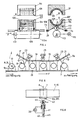
- FIG. 1 shows a side view of a first embodiment variant of the method according to the invention or of a device designed for this.
- this exemplary embodiment it is a question of coating, as a workpiece, tubular components which are open on both sides, for example and in particular can bodies, on their inner walls in a known manner, be this in whole or, on this wall, only preferred parts, in particular the batch of the can body weld.
- a work arm 3 is provided for the inner coating of the can frames 1, which projects further from a welding arm to close the frames which were previously still open.
- At least one feed line 5 for coating medium is provided in arm 3, possibly also a return suction line 6 for medium not applied and, in the case of electrostatically assisted coating, the electrical supply (not shown) for a high-voltage electrode arrangement.
- a nozzle arrangement 5 is provided on the arm 3, a nozzle arrangement 5a for coating a longitudinally extended inner wall area, such as the weld seam area, or a nozzle arrangement 5b for spraying out the entire inner wall of the can body.
- the can bodies 1 are driven in rapid succession along the working arm 3 by means of a conveyor device with an endless belt 7, be it a plastic, a metal or a chain belt.
- a conveyor device with an endless belt 7, be it a plastic, a metal or a chain belt.
- holding members 9a according to the invention are now attached to the belt 7 at regular intervals, which initially serve to advance the can bodies 1 in a defined position along the working arm 3.
- the conveyor belt 7 is driven in a conventional manner and depending on its design by drive rollers and guided by guide rollers, one of which, 11, is shown in FIG. 2.
- the holding members 9a are trough-shaped, with a trough 13 which extends parallel to the longitudinal extension of the band 7. Lying in this tub 13, the respective can body 1, as again clearly shown in FIG. 2, is advanced.
- the tub 13 is dimensioned such that it essentially directly covers and covers half the circumferential surface of the outer frame wall in a form-fitting manner.
- a second conveyor belt 15 is provided, which runs in front of the area on the working arm 3 with the spray nozzle arrangement 5a or 5b against the conveyor belt 7, in a first area 17, thereafter at least substantially parallel to the conveyor belt 7 runs, in an area 19 and after the spray nozzle arrangement 5a or 5b again pivots away from the conveyor belt 7 into an area 21.
- the holding members 9a are fastened to the band 7 in such a way that their deflections can easily follow, as shown at 29, for example, so that they are pivotally connected within limits.
- the cover jaws 9b are constructed at least substantially the same as the holding jaws 9a, ie they also have a trough-shaped indentation 31 , which in turn corresponds at least essentially to half the outer surface of the can body.
- the covering jaws 9b in front of the nozzle arrangements 5a and 5b, are moved against the frames 1 inserted in the troughs 13 of the holding jaws 9a, and then, in the web area 19 of the conveyor belt 15, they fit snugly the outer wall of the can body 1 in such a way that the latter are now covered essentially in a form-fitting manner on their entire outer surface by the holding jaws 9a and the covering jaws 9b, which now also act as covering jaws.
- the can bodies are moved along the nozzle arrangements 5a and 5b and powder-coated or lacquered on their inner wall in the required manner.
- the second band 15, as shown in FIG. 1 in the region 21 bends away from the band 7 again, and the cover jaws 9b are lifted off the can bodies 1 again.
- the conveyor belts 7 and 15 preferably move the latter with the jaws 9a and 9b through cleaning stations 33a and 33b, as shown schematically in FIG. 1. In it, the jaws 9a and 9b are cleaned of the coating medium to which they were exposed due to their covering effect during the coating process.
- this procedure has the advantage that, for the temperature reasons mentioned, relatively expensive insert material for the inserts 35, such as Teflon, has to be used, that the contaminated insert 35 can be removed, new inserts can be introduced and the contaminated inserts can be cleaned centrally , while the coating system continues to work practically without interruption.
- the insert cleaning then does not have to be carried out in a continuous cleaning process, but can be carried out anywhere.
- the diameter D of the covering troughs on the jaws 9a and 9b can be changed by thicker or thinner inserts 35, which means that the device can be quickly converted for processing different sizes of can bodies 1.
- the trough parts 37 of the inserts 35 can be designed to be elastic, so that the covering form fit of the interacting jaws 9a and 9b is increased.
- FIG. 4 A further embodiment variant of the one already illustrated with reference to FIG. 1 is now shown schematically in FIG. 4.
- the entire inner wall of the can body 1 is to be coated with the procedure shown in FIG. 1, it can be advantageous to rotate the can body about its longitudinal axis A according to FIG. 1 during the coating process.
- rollers 101 are arranged on the cover jaws 9b, along their trough parts 31, freely rotating axially parallel to the trough axis B. Both end portions of the cover jaws 9b are formed with protruding collars 103, which protrude in such a way that the rollers 101 protrude only minimally above the collars 103. With an inserted (not shown here ) can bodies lie primarily on the rollers 101, and a thin air gap remains between their outer wall and the collar 103. A can body inserted into the cover jaw 9b in this way is also covered by this jaw 9b to prevent contamination by the coating medium.
- the holding jaws 9a in turn have freely running, axially aligned rollers 105 along their troughs 13 and, also at the end, as described with respect to the jaws 9b, have a collar 107.
- balls can also be provided instead of the free-running rollers described so far.
- the stacked jaws 9a and 9b result in either a ball bushing or a roller bushing.
- a can body 1 inserted between these jaws can be rotated about its axis A with little resistance.
- the lowermost roller 109 in the plane of symmetry E is now in frictional engagement with a transfer roller 111 mounted rotatably on the jaw 9a.
- the roller 109 is preferably resiliently mounted in the direction of the plane E and can, to a limited extent, and as shown in broken lines at 111, be lifted into the tub 13 against the force of a spring element, for example on its bearings.
- the transfer roller 111 is preferably not only rotatable on the jaw 9a, but, as with the spring bearing 113 and the arrow P Darge provides resiliently movable in the direction of the plane E.
- the jaws 109 are mounted on hinges 7a, 7b, which are preferably arranged on both sides in this embodiment, in an articulated manner, as shown at 29, in order to follow the path of the strap 7 according to FIG. 1.
- a drive roller 113 is now rotatably mounted on the system and is driven by a motor 115.
- the drive roller 113 like the roller 111 on the jaw 9a, has a friction lining and is preferably driven permanently by the motor 115.
- the transfer roller 111 comes into frictional contact with the stationary drive roller 113 during its axial feed movement, which is what is facilitated by the bevelled end faces 113a on the roller 113, in particular since the aforementioned resilient mounting of the transfer roller 111 is provided, which now ensures a good frictional connection between the drive roller 113 and the transfer roller 111.
- FIG. 5 is a further embodiment variant of the procedure according to the invention in a representation analogous to FIG. 1 shown, which, as will be explained below, is now, in contrast to that of FIG. 1, also suitable for hollow workpieces which are closed on one side, in particular for semi-finished cans with an already molded or attached base piece.
- the fundamentally the same components as have already been used and described have the same position symbols and are not described again.
- the holding jaws 9a are arranged on the belt 7 in such a way that the longitudinal axes B of their troughs 13 lie transversely to the conveying direction of the belt 7.
- the workpieces or can bodies or semi-finished product bodies to be coated on the inside in whole or in part, on both sides or closed on one side, are therefore inserted into the holding jaws 9a with their axis A lying transverse to the conveying direction of the belt 7.
- cover jaws 9b are mounted in such a way that their trough longitudinal axes B lie transversely to the conveying movement direction F by means of belt 15.
- a spray lance 41 driven by a motor, by means of a schematically illustrated drive 39 and coaxial with the longitudinal axis A of the workpieces or the longitudinal axes of the tubs B on the jaws 9a or 9b, is inserted into Moving interior of the workpieces 1, and during the moving in and / or thereafter in a standstill phase of the spray lance 41 and / or during its withdrawal from the interior of the workpieces 1, a batch or preferably the entire interior of the workpieces 1 is sprayed with powder or wet paint. It is also possible to To position the spray lance 41, for example, so that its spray mouth is immediately in front of or at the opening 42 of the workpiece 1. If the lance is moved axially, as shown schematically in FIG. 6, the supply line 43 for coating medium and, as also shown schematically at 6 in FIG. 1, a return suction line 45 for sucking back excess coating medium are flexibly formed on it.
- the entire arrangement with the belts 7 and 15 is preferably stopped in the area 19 in a clocked manner and one or more coating lances are then actuated for spraying.
- the jaws 9a, 9b are designed according to the explanations relating to FIG. 4, i.e. with free-running rollers arranged in the tubs, in particular because, during the coating process, the workpieces 1 and therefore the jaws 9a and 9b are stationary, there is a simple possibility of also causing the workpieces to rotate during the spraying process when the lance is sprayed according to FIG. 5 .
- this is drivingly one or more of the rollers shown in FIG. 4, or, in the case of workpieces made of magnetic material, for example a magnetic coupling, the workpieces on the side of the jaws 9a facing away from the lances, 9b coupled.
- Another variant is to set the nozzle area on the lances in rotational movement in the simplest way by the pressure of the pre-conveyed spray medium itself, as is known in principle for water in sprinkler systems.
- a mounting plate 51 is provided, which is preferably rigidly connected to the carrier mandrel 49, as well as to the band 47, provided that the workpieces 1, as here again two-sided open can bodies, are not to rotate about their axis A during their external coating or which with respect to the belt 47, such as by means of a ball bearing arrangement, is rotatable about the axis A.
- a rubber-elastic stocking 53 is anchored to the plate 51 and extends over the mandrel 49.
- a pressure medium line 55 runs coaxially through the mandrel 49, which extends through the band 47 and, with respect to the mandrel 49, opens out on the rear side thereof.
- a check valve (not shown) is provided on the outlet part 57 of the pressure medium line 55.
- the opening 57 is formed by a hollow axle stub, the inner bore of which communicates on the one hand with the line 55, which on the other hand is rigidly connected to the mandrel 49 and has, for example, an external toothing 59 on which one Drive arrangement 61 can engage with drive shaft 63 and internal toothing 65 in order to set the mandrel 49 in rotation about the axis A via the connecting piece of the line 55, as indicated by ⁇ .
- a drive station 61 is provided at at least one predetermined point, opposite the mandrels 49, which is connected on the one hand to a pressure medium source via a line 63 and which, if the mandrel 49 is to be rotated during the coating process, has a drive unit 67.
- workpieces 1, such as can bodies 1 which are open on both sides, are placed on stocking 53 and mandrel 49 in the state of the stocking 53 not initially pressurized and then take the one shown in FIG. 6 with respect to the axis A of the Dornes 49 eccentric location.
- the workpieces 1 are held relatively loosely. If a relatively long conveying path has to be traveled from this position of the belt 47 to the coating station, then the latter is inflated immediately after a position at which the workpieces are placed over the mandrels and the still loose stockings 53.
- stations 61 are provided in this position, apart from the coating station, which are not provided with the drive unit 67, but only with a pressure medium supply line 63.
- positioning rollers 56 are provided, acting as stops.
- a connection to the line 55 is made sealingly by axially advancing a connecting piece on the unit 61 and the stocking 53 is inflated.
- dashed lines in FIG. 7 it now assumes a position corresponding to 53a and in the process lifts the workpiece 1 into a position coaxial with the axis A of the mandrel 49, possibly also fixed by the positioning cams 56. This position is also dashed in Fig. 7 and designated 1a.
- the workpieces 1a are now conveyed further, as can be seen in FIG. 8, the inner walls of the workpieces 1a being covered cleanly by the tight application of the pressurized stocking.
- one or more coating stations 69 are provided for spraying the workpieces outside with powder or wet paint.
- the stations 69 have the schematically represented coating medium supply lines 71 or, for sucking back excess coating medium, the return suction lines 73. Since any positioning cams or rollers 56 provided are inside, they do not interfere with the coating process.
- the coating stations 69 can be lance-shaped coating lances pushed over the workpieces brought into the coating position, which are put over the workpieces and in which, for example, outlet openings for the coating medium are regularly distributed along their inner surface, as is shown in FIG. 9 is shown schematically. If the coating arrangements 69 are designed in this way, ie if the outer surface of the workpieces 1a is coated with this regularly and distributed over the circumference, in most cases the workpieces 1a are rotated their own axis A is not required during the coating process.
- a unit 61 which is now only designed as a drive arrangement, is provided, as shown schematically in FIG. 8, which engages with an axle stub with internal teeth 65 on the connecting piece with external teeth 59 and during coating, ie synchronized with the latter, mandrel and thus the centered workpiece 1 a rotated.
- the belt 47 is conveyed further, and the pressure is released from the stocking 53 at an outlet station by engaging the check valve, so that the now externally coated workpieces 1a can then be removed and further conveyed and processed in any manner.
- FIG. 10 schematically shows the various functional sequences of the procedure according to the invention or the device according to FIGS. 7 to 9.
- Workpieces 1 are coated on the outside with a coating arrangement which covers only one area of the Workpiece outer wall sprayed at the same time, with which the workpieces have to be rotated to obtain a uniform coating of their entire outer surface.
- workpieces 1 are loaded onto the mandrels 49 with loose stockings 53.
- the stockings 53 are inflated by connection to connecting pieces 60, with the workpieces 1 being centered in the position corresponding to 1a will.
- the workpieces 1a are then conveyed further in this centered position, the pressure in the stockings being maintained on account of the action of the check valve provided.
- the nozzles 60 are mechanically coupled to a unit 61b and rotated by a motor and at the same time coated on the outside by means of the coating device 69. Thereafter, the workpieces 1a are now coated on the outside and continue to be centered, conveyed on to a station 61c, at which, as shown with the schematic intervention 71, the check valve is opened, the stocking collapses, so that the workpieces 1 can now be unloaded.
- the processing can of course, since it must be carried out in a clocked manner, be carried out simultaneously on a plurality of workpieces 1, for example on five or ten, so that in each case a group of workpieces 1 to be machined is always loaded, positioned, pushed on, coated, etc.
- sealing against coating medium by means of labyrinth seals can also be provided, which at least in sections of the workpiece surfaces to be covered leave air gaps.
Landscapes
- Spray Control Apparatus (AREA)
- Details Or Accessories Of Spraying Plant Or Apparatus (AREA)
- Application Of Or Painting With Fluid Materials (AREA)
- Agricultural Chemicals And Associated Chemicals (AREA)
Applications Claiming Priority (2)
| Application Number | Priority Date | Filing Date | Title |
|---|---|---|---|
| DE3932312 | 1989-09-28 | ||
| DE3932312A DE3932312A1 (de) | 1989-09-28 | 1989-09-28 | Verfahren und anlage zur spruehbeschichtung von werkstuecken |
Publications (3)
| Publication Number | Publication Date |
|---|---|
| EP0420038A2 true EP0420038A2 (fr) | 1991-04-03 |
| EP0420038A3 EP0420038A3 (en) | 1992-01-02 |
| EP0420038B1 EP0420038B1 (fr) | 1995-03-08 |
Family
ID=6390336
Family Applications (1)
| Application Number | Title | Priority Date | Filing Date |
|---|---|---|---|
| EP90118090A Expired - Lifetime EP0420038B1 (fr) | 1989-09-28 | 1990-09-20 | Procédé et dispositif de revêtement de pièces creuses par pulvérisation |
Country Status (6)
| Country | Link |
|---|---|
| US (1) | US5258073A (fr) |
| EP (1) | EP0420038B1 (fr) |
| JP (1) | JP2661784B2 (fr) |
| AT (1) | ATE119435T1 (fr) |
| DE (2) | DE3932312A1 (fr) |
| ES (1) | ES2069645T3 (fr) |
Cited By (1)
| Publication number | Priority date | Publication date | Assignee | Title |
|---|---|---|---|---|
| CN119869830A (zh) * | 2025-03-28 | 2025-04-25 | 南通创源电化学科技有限公司 | 一种汽车金属零部件表面处理设备及方法 |
Families Citing this family (17)
| Publication number | Priority date | Publication date | Assignee | Title |
|---|---|---|---|---|
| US5474807A (en) * | 1992-09-30 | 1995-12-12 | Hoya Corporation | Method for applying or removing coatings at a confined peripheral region of a substrate |
| DE4318048A1 (de) * | 1993-05-29 | 1994-12-01 | Herberts Gmbh | Verfahren zum abfallfreien Spritzlackieren von zylindrischen Körpern |
| DE19514057A1 (de) * | 1995-04-13 | 1996-10-17 | Daniel Seiler | Anlage zum elektrostatischen Beschichten flacher Werkstücke |
| DE59610063D1 (de) * | 1995-05-12 | 2003-02-27 | Elpatronic Ag Bergdietikon | Verfahren und Vorrichtung zur Innenbeschichtung von Behälterzargen |
| DE19630290C2 (de) * | 1996-07-26 | 2000-08-10 | Audi Ag | Anlage zur Oberflächenbehandlung von Gegenständen, insbesondere von Fahrzeugkarosserien |
| US20050025888A1 (en) * | 2003-07-31 | 2005-02-03 | Graham Packaging, Inc. | Method for shielding articles on a coating line |
| WO2005105318A1 (fr) * | 2004-04-30 | 2005-11-10 | Orisol Asia Ltd. | Revetement adhesif forme par pulverisation a charge electrostatique |
| JP5427749B2 (ja) * | 2010-10-19 | 2014-02-26 | キヤノン化成株式会社 | 弾性ローラの製造方法 |
| WO2013096436A1 (fr) * | 2011-12-22 | 2013-06-27 | First Solar, Inc. | Système et procédé de nettoyage de substrat photovoltaïque |
| FR3052086B1 (fr) * | 2016-06-07 | 2018-06-15 | Louis Vuitton Malletier | Systeme pour tester un parfum |
| CN115157551B (zh) * | 2021-04-01 | 2024-12-10 | 惠亚科技(东台)有限公司 | 供应设备 |
| CN113546817B (zh) * | 2021-07-09 | 2023-03-31 | 江苏华尔能科技股份有限公司 | 电力柜外绝缘疏水性粉末均匀涂覆装置 |
| CN116180359B (zh) * | 2021-11-29 | 2024-08-16 | 浙江云中马股份有限公司 | 一种防色迁的彩色革基布喷涂装置 |
| CN114308485A (zh) * | 2022-01-07 | 2022-04-12 | 张东林 | 一种防护膜涂覆系统及控制方法 |
| CN115532512B (zh) * | 2022-10-25 | 2025-07-15 | 扬州万泰电子科技有限公司 | 智能电表自动化生产线 |
| DE102024125449A1 (de) * | 2024-09-05 | 2025-10-23 | Comau S.P.A. | Transportvorrichtung für eine Lackieranlage zum Lackieren von Objekten, Lackieranlage und Verfahren zum Transportieren von Objekten durch einen Applikationsbereich einer Lackieranlage |
| CN120534673B (zh) * | 2025-07-28 | 2025-09-30 | 江苏正通金属封头有限公司 | 一种封头加工上料装置 |
Family Cites Families (11)
| Publication number | Priority date | Publication date | Assignee | Title |
|---|---|---|---|---|
| US3296999A (en) * | 1963-11-27 | 1967-01-10 | Continental Can Co | Apparatus for shielding pail open tops while spraying body exteriors |
| FR2099307A5 (fr) * | 1970-06-29 | 1972-03-10 | Shinko Electric Co Ltd | |
| US3802380A (en) * | 1971-08-26 | 1974-04-09 | Sangamo Electric Co | Apparatus for applying an insulating coating on capacitor cans |
| US3855966A (en) * | 1973-11-30 | 1974-12-24 | Wheaton Industries | Universal chucking mechanism |
| DE2558846A1 (de) * | 1975-12-27 | 1977-07-07 | Villeroy & Boch | Verfahren und vorrichtung zum aufbringen eines dekors auf einen formling |
| US4075975A (en) * | 1976-10-06 | 1978-02-28 | Kaiser Steel Corporation | Rotator and coater system for drum shells |
| JPS6110780Y2 (fr) * | 1980-06-16 | 1986-04-05 | ||
| US4319543A (en) * | 1980-08-25 | 1982-03-16 | Anchor Hocking Corporation | Container masking and coating apparatus |
| JPS6135877A (ja) * | 1984-07-30 | 1986-02-20 | Sumitomo Metal Ind Ltd | 鋼板の額縁塗装装置 |
| JPS61175272U (fr) * | 1985-04-18 | 1986-10-31 | ||
| JPH0624659B2 (ja) * | 1986-06-04 | 1994-04-06 | 北海製罐株式会社 | 缶胴体の塗装方法および塗装装置 |
-
1989
- 1989-09-28 DE DE3932312A patent/DE3932312A1/de active Granted
-
1990
- 1990-09-20 DE DE59008630T patent/DE59008630D1/de not_active Expired - Fee Related
- 1990-09-20 ES ES90118090T patent/ES2069645T3/es not_active Expired - Lifetime
- 1990-09-20 EP EP90118090A patent/EP0420038B1/fr not_active Expired - Lifetime
- 1990-09-20 AT AT90118090T patent/ATE119435T1/de not_active IP Right Cessation
- 1990-09-25 JP JP2255017A patent/JP2661784B2/ja not_active Expired - Fee Related
- 1990-09-28 US US07/589,512 patent/US5258073A/en not_active Expired - Fee Related
Cited By (1)
| Publication number | Priority date | Publication date | Assignee | Title |
|---|---|---|---|---|
| CN119869830A (zh) * | 2025-03-28 | 2025-04-25 | 南通创源电化学科技有限公司 | 一种汽车金属零部件表面处理设备及方法 |
Also Published As
| Publication number | Publication date |
|---|---|
| EP0420038A3 (en) | 1992-01-02 |
| ES2069645T3 (es) | 1995-05-16 |
| DE59008630D1 (de) | 1995-04-13 |
| ATE119435T1 (de) | 1995-03-15 |
| US5258073A (en) | 1993-11-02 |
| JP2661784B2 (ja) | 1997-10-08 |
| DE3932312A1 (de) | 1991-04-11 |
| DE3932312C2 (fr) | 1992-06-11 |
| EP0420038B1 (fr) | 1995-03-08 |
| JPH03242255A (ja) | 1991-10-29 |
Similar Documents
| Publication | Publication Date | Title |
|---|---|---|
| EP0420038B1 (fr) | Procédé et dispositif de revêtement de pièces creuses par pulvérisation | |
| DE69224998T2 (de) | Vorrichtung zur verminderung des abstandes und der geschwindigkeit von blechdosen | |
| CH676208A5 (fr) | ||
| DE2346587A1 (de) | Vorrichtung zum schneiden und auftragen von bandabschnitten | |
| DE2724625A1 (de) | Vorrichtung zur entnahme und ablage von suesswarenerzeugnissen | |
| EP3339222B1 (fr) | Dispositif de transport pour ébauches de boîte | |
| DE1696653B2 (de) | Verfahren und einrichtung zum aufbringen eines ueberzuges | |
| EP2429728B1 (fr) | Procédé et dispositif pour le nettoyage intérieur de boîtes présentant chacune une ouverture | |
| DE2518524A1 (de) | Entnahmevorrichtung fuer kapselsortiermaschinen | |
| DE69108323T2 (de) | Untereinheit zur Dornverschiebung für Dosendekoriermaschine mit kontinuierlicher Bewegung. | |
| DE2227369A1 (de) | Vorrichtung zum automatischen abloesen von knochen aus fleisch, insbesondere aus schinken | |
| DE3318810A1 (de) | Vorrichtung zum dosierten abfuellen pharmazeutischer pasten | |
| DE2203996B2 (de) | Vorrichtung zum Aufbringen von Vorder- und Rückenetiketten auf Gegenstände, vorzugsweise Flaschen | |
| DE69510396T2 (de) | Schneidevorrichtung für Belagblättchen in einer Filteransetzmaschine | |
| DE69508602T2 (de) | Vorrichtung zum aufbringen von creme | |
| DE102009021137B4 (de) | Verfahren und Vorrichtung zum Waschen und Spülen von Hohlkörpern | |
| DE2156298A1 (de) | Vorrichtung zum elektrostatischen Bedrucken von gekrümmten Oberflächen | |
| DE2935874A1 (de) | Verfahren und vorrichtung zum spritzlackieren von am boden geschlossenen behaeltern, insbesondere dosen | |
| DE4422061A1 (de) | Vorrichtung und Verfahren zur Entnahme von Teilen aus einem Aufnahmeraum z. B. zum Füllen von Behältern | |
| DE2817825C2 (fr) | ||
| DE516168C (de) | Beilageneinsteckmaschine | |
| DE3229383A1 (de) | Verfahren zur entfernung von partikeln aus bechern und vorrichtung zur durchfuehrung des verfahrens | |
| EP3486182B1 (fr) | Tête rotative à canal pliant à mobilité longitudinale | |
| AT404718B (de) | Vorrichtung zur übergabe von flachen werkstücken von einem ersten förderer an einen zweiten nachgeschalteten förderer | |
| DE4437379C2 (de) | Verfahren und Vorrichtung zum Übertragen von Druckbildern auf kontinuierlich geförderte Gegenstände |
Legal Events
| Date | Code | Title | Description |
|---|---|---|---|
| PUAI | Public reference made under article 153(3) epc to a published international application that has entered the european phase |
Free format text: ORIGINAL CODE: 0009012 |
|
| AK | Designated contracting states |
Kind code of ref document: A2 Designated state(s): AT BE CH DE DK ES FR GB GR IT LI LU NL SE |
|
| PUAL | Search report despatched |
Free format text: ORIGINAL CODE: 0009013 |
|
| AK | Designated contracting states |
Kind code of ref document: A3 Designated state(s): AT BE CH DE DK ES FR GB GR IT LI LU NL SE |
|
| 17P | Request for examination filed |
Effective date: 19920630 |
|
| 17Q | First examination report despatched |
Effective date: 19931013 |
|
| GRAA | (expected) grant |
Free format text: ORIGINAL CODE: 0009210 |
|
| AK | Designated contracting states |
Kind code of ref document: B1 Designated state(s): AT BE CH DE DK ES FR GB GR IT LI LU NL SE |
|
| PG25 | Lapsed in a contracting state [announced via postgrant information from national office to epo] |
Ref country code: NL Free format text: LAPSE BECAUSE OF NON-PAYMENT OF DUE FEES Effective date: 19950308 Ref country code: GR Free format text: LAPSE BECAUSE OF FAILURE TO SUBMIT A TRANSLATION OF THE DESCRIPTION OR TO PAY THE FEE WITHIN THE PRESCRIBED TIME-LIMIT Effective date: 19950308 Ref country code: DK Effective date: 19950308 Ref country code: BE Effective date: 19950308 |
|
| REF | Corresponds to: |
Ref document number: 119435 Country of ref document: AT Date of ref document: 19950315 Kind code of ref document: T |
|
| REF | Corresponds to: |
Ref document number: 59008630 Country of ref document: DE Date of ref document: 19950413 |
|
| GBT | Gb: translation of ep patent filed (gb section 77(6)(a)/1977) |
Effective date: 19950410 |
|
| REG | Reference to a national code |
Ref country code: ES Ref legal event code: FG2A Ref document number: 2069645 Country of ref document: ES Kind code of ref document: T3 |
|
| ITF | It: translation for a ep patent filed | ||
| PG25 | Lapsed in a contracting state [announced via postgrant information from national office to epo] |
Ref country code: SE Effective date: 19950608 |
|
| ET | Fr: translation filed | ||
| NLV1 | Nl: lapsed or annulled due to failure to fulfill the requirements of art. 29p and 29m of the patents act | ||
| PG25 | Lapsed in a contracting state [announced via postgrant information from national office to epo] |
Ref country code: AT Effective date: 19950920 |
|
| PG25 | Lapsed in a contracting state [announced via postgrant information from national office to epo] |
Ref country code: LU Free format text: LAPSE BECAUSE OF NON-PAYMENT OF DUE FEES Effective date: 19950930 |
|
| PLBE | No opposition filed within time limit |
Free format text: ORIGINAL CODE: 0009261 |
|
| STAA | Information on the status of an ep patent application or granted ep patent |
Free format text: STATUS: NO OPPOSITION FILED WITHIN TIME LIMIT |
|
| 26N | No opposition filed | ||
| REG | Reference to a national code |
Ref country code: CH Ref legal event code: PUE Owner name: PRAEZISIONS-WERKZEUGE AG TRANSFER- ELPATRONIC AG |
|
| REG | Reference to a national code |
Ref country code: CH Ref legal event code: NV Representative=s name: TROESCH SCHEIDEGGER WERNER AG |
|
| REG | Reference to a national code |
Ref country code: FR Ref legal event code: TP |
|
| REG | Reference to a national code |
Ref country code: GB Ref legal event code: 732E |
|
| REG | Reference to a national code |
Ref country code: GB Ref legal event code: IF02 |
|
| PGFP | Annual fee paid to national office [announced via postgrant information from national office to epo] |
Ref country code: FR Payment date: 20040908 Year of fee payment: 15 |
|
| PGFP | Annual fee paid to national office [announced via postgrant information from national office to epo] |
Ref country code: GB Payment date: 20040915 Year of fee payment: 15 |
|
| PGFP | Annual fee paid to national office [announced via postgrant information from national office to epo] |
Ref country code: DE Payment date: 20040916 Year of fee payment: 15 |
|
| PGFP | Annual fee paid to national office [announced via postgrant information from national office to epo] |
Ref country code: ES Payment date: 20040929 Year of fee payment: 15 |
|
| PGFP | Annual fee paid to national office [announced via postgrant information from national office to epo] |
Ref country code: CH Payment date: 20041124 Year of fee payment: 15 |
|
| PG25 | Lapsed in a contracting state [announced via postgrant information from national office to epo] |
Ref country code: IT Free format text: LAPSE BECAUSE OF NON-PAYMENT OF DUE FEES Effective date: 20050920 Ref country code: GB Free format text: LAPSE BECAUSE OF NON-PAYMENT OF DUE FEES Effective date: 20050920 |
|
| PG25 | Lapsed in a contracting state [announced via postgrant information from national office to epo] |
Ref country code: ES Free format text: LAPSE BECAUSE OF NON-PAYMENT OF DUE FEES Effective date: 20050921 |
|
| PG25 | Lapsed in a contracting state [announced via postgrant information from national office to epo] |
Ref country code: LI Free format text: LAPSE BECAUSE OF NON-PAYMENT OF DUE FEES Effective date: 20050930 Ref country code: CH Free format text: LAPSE BECAUSE OF NON-PAYMENT OF DUE FEES Effective date: 20050930 |
|
| PG25 | Lapsed in a contracting state [announced via postgrant information from national office to epo] |
Ref country code: DE Free format text: LAPSE BECAUSE OF NON-PAYMENT OF DUE FEES Effective date: 20060401 |
|
| REG | Reference to a national code |
Ref country code: CH Ref legal event code: PL |
|
| GBPC | Gb: european patent ceased through non-payment of renewal fee |
Effective date: 20050920 |
|
| PG25 | Lapsed in a contracting state [announced via postgrant information from national office to epo] |
Ref country code: FR Free format text: LAPSE BECAUSE OF NON-PAYMENT OF DUE FEES Effective date: 20060531 |
|
| REG | Reference to a national code |
Ref country code: FR Ref legal event code: ST Effective date: 20060531 |
|
| REG | Reference to a national code |
Ref country code: ES Ref legal event code: FD2A Effective date: 20050921 |