EP0420071A1 - Verfahren zum Verpacken durch Zusammenpressen und Vorrichtung zum Bündeln von zu verpackenden Produkten - Google Patents
Verfahren zum Verpacken durch Zusammenpressen und Vorrichtung zum Bündeln von zu verpackenden Produkten Download PDFInfo
- Publication number
- EP0420071A1 EP0420071A1 EP90118222A EP90118222A EP0420071A1 EP 0420071 A1 EP0420071 A1 EP 0420071A1 EP 90118222 A EP90118222 A EP 90118222A EP 90118222 A EP90118222 A EP 90118222A EP 0420071 A1 EP0420071 A1 EP 0420071A1
- Authority
- EP
- European Patent Office
- Prior art keywords
- bundling
- reinforcement
- packed
- article
- reinforcements
- Prior art date
- Legal status (The legal status is an assumption and is not a legal conclusion. Google has not performed a legal analysis and makes no representation as to the accuracy of the status listed.)
- Granted
Links
- 238000012856 packing Methods 0.000 title claims abstract description 49
- 238000000034 method Methods 0.000 title claims abstract description 35
- 230000002787 reinforcement Effects 0.000 claims abstract description 160
- 239000000463 material Substances 0.000 claims abstract description 62
- 210000005069 ears Anatomy 0.000 claims description 12
- 238000007493 shaping process Methods 0.000 claims description 6
- 230000006835 compression Effects 0.000 description 37
- 238000007906 compression Methods 0.000 description 37
- -1 polypropylene Polymers 0.000 description 10
- 239000004698 Polyethylene Substances 0.000 description 7
- 238000011109 contamination Methods 0.000 description 6
- 229920000573 polyethylene Polymers 0.000 description 6
- 230000008569 process Effects 0.000 description 6
- 239000000835 fiber Substances 0.000 description 5
- 238000002156 mixing Methods 0.000 description 5
- 238000011282 treatment Methods 0.000 description 5
- QTBSBXVTEAMEQO-UHFFFAOYSA-M Acetate Chemical compound CC([O-])=O QTBSBXVTEAMEQO-UHFFFAOYSA-M 0.000 description 4
- 241000208125 Nicotiana Species 0.000 description 4
- 235000002637 Nicotiana tabacum Nutrition 0.000 description 4
- 239000004743 Polypropylene Substances 0.000 description 4
- 239000004744 fabric Substances 0.000 description 4
- 239000002655 kraft paper Substances 0.000 description 4
- 229920001155 polypropylene Polymers 0.000 description 4
- 230000007246 mechanism Effects 0.000 description 3
- 239000002184 metal Substances 0.000 description 3
- 229910052751 metal Inorganic materials 0.000 description 3
- 239000002985 plastic film Substances 0.000 description 3
- 238000002360 preparation method Methods 0.000 description 3
- 230000000630 rising effect Effects 0.000 description 3
- 238000004904 shortening Methods 0.000 description 3
- 238000003860 storage Methods 0.000 description 3
- 229920000742 Cotton Polymers 0.000 description 2
- 241001052209 Cylinder Species 0.000 description 2
- 239000000470 constituent Substances 0.000 description 2
- 230000009975 flexible effect Effects 0.000 description 2
- 239000002648 laminated material Substances 0.000 description 2
- 239000005022 packaging material Substances 0.000 description 2
- 238000003825 pressing Methods 0.000 description 2
- 230000009467 reduction Effects 0.000 description 2
- 230000004044 response Effects 0.000 description 2
- 238000007792 addition Methods 0.000 description 1
- 230000015556 catabolic process Effects 0.000 description 1
- 238000010586 diagram Methods 0.000 description 1
- 208000016509 ear folding Diseases 0.000 description 1
- 238000009434 installation Methods 0.000 description 1
- 238000005304 joining Methods 0.000 description 1
- 238000004519 manufacturing process Methods 0.000 description 1
- 150000002739 metals Chemical class 0.000 description 1
- 230000007935 neutral effect Effects 0.000 description 1
- 230000000149 penetrating effect Effects 0.000 description 1
- 230000003014 reinforcing effect Effects 0.000 description 1
- 239000000126 substance Substances 0.000 description 1
- 238000010626 work up procedure Methods 0.000 description 1
Images


Classifications
-
- B—PERFORMING OPERATIONS; TRANSPORTING
- B65—CONVEYING; PACKING; STORING; HANDLING THIN OR FILAMENTARY MATERIAL
- B65B—MACHINES, APPARATUS OR DEVICES FOR, OR METHODS OF, PACKAGING ARTICLES OR MATERIALS; UNPACKING
- B65B27/00—Bundling particular articles presenting special problems using string, wire, or narrow tape or band; Baling fibrous material, e.g. peat, not otherwise provided for
- B65B27/12—Baling or bundling compressible fibrous material, e.g. peat
- B65B27/125—Baling or bundling compressible fibrous material, e.g. peat and wrapping or bagging
Definitions
- the present invention relates to a method for compressive packing, in which an article to be packed, which must avoid mixing of foreign matters, contamination and biting by bundling belts, such as tow for tobacco filter, sanitary cotton, etc. is packed continuously and automatically by adding a series of functions to a compressive packing apparatus, and also relates to an apparatus for bundling an article to be packed.
- a method of wrapping an article to be packed with a sheet of stuck type or laminated type consisting of a polypropylene Hessian cloth and a polyethylene sheet or with a kraft paper sheet having a polyethylene film lining, thereafter protecting the outside of the wrapped article with reinforcement members which are excellent in both rigidity and strength such as corrugated cardboard sheets or plastic sheets, and then bundling the articles with bands or wires, has been heretofore employed, but such steps of the method were carried out by handwork in the prior art.
- a method for producing a package bale consisting of the steps of compressively shaping the article to be packed from either direction or both directions of the upward and downward directions within a compressing box for shaping, whose upper and lower surfaces are opened and whose four side surfaces can be arbitrarily opened or closed, thereafter opening the four side surfaces of the compression box, preliminarily mounting upper and lower reinforcements to upper and lower press seats of the compression box by handwork, wrapping the articles to be packed by handwork by making use of upper and lower wrapping materials for directly wrapping the article to be packed, which wrapping material is placed between the reinforcement and the articles to be packed, thereafter attaching reinforcements consisting of 2 to 4 pieces for reinforcing four side surfaces of the article to be packed onto these side surfaces by handwork, subsequently bundling the reinforcements by handwork by means of a number
- Fig. 10 is a front view of a compressive packing machine in the prior art
- Fig. 11 is a cross-section view taken along line XI-XI in Fig. 10(a).
- Fig. 1 shows an outline of a series of packing works including the steps of wrapping, mounting of reinforcements and bundling by handwork by means of the above-described type of compressive packing machine (It is to be noted that Fig. 1 was originally prepared for explaining the present invention, and so, only the portions necessitated for explaining the method for compressive packing by handwork are explained here.)
- An article to be packed such as acetate tow is stored in an enclosure box 1 shown in Fig. 10 in the preceding step of the process, thereafter they are carried into the center of a compressive packing machine by transport means such as a conveyor not shown as shown in Fig. 10(a), and they are further positioned by means of a positioning device 2.
- reinforcements 5a and 5b such as corrugated cardboard sheets, kraft paper sheets or plastic sheets are mounted to an upper press seat 3 and a lower press seat 4 of the compressive packing machine jointly with wrapping materials 6a and 6b having flexibility such as a polypropylene Hessian cloth and a polyethylene sheet in combination as stuck or laminated together with retainer metals 7a and 7b, respectively, by handwork as will be described later.
- wrapping materials 6a and 6b having flexibility such as a polypropylene Hessian cloth and a polyethylene sheet in combination as stuck or laminated together with retainer metals 7a and 7b, respectively, by handwork as will be described later.
- the upper press seat 3 is present at the limit (illustrated) position of rising as accompanied by the above-described reinforcement 5a and wrapping material 6a.
- the lower press seat 4 is present in the proximity of the top level of a fixed frame 8 (the limit position of rising) as accompanied by the reinforcement 5b and wrapping material 6b, and large doors 10a and 10b and a small door 11 in a compressing box assembly 9 are in a closed state. It is to be noted that the state depicted by double-dot chain lines of the large doors 10a and 10b in Fig. 11 is an opened state.
- the enclosure box 1 is once lowered up to a neutral position 13 by means of an enclosure box elevator 12 associated with the compressive packing machine, here a tow receiver 14 of the enclosure box 1 is opened by a tow receiver opening/closing device not shown at the bottom of the enclosure box and continuously it is lowered up to a position overlapping with the top of the fixed frame 8 (the limit position of lowering).
- the lower press seat 4 is pulled down by means of a hydraulic cylinder 16 or the like while supporting tow 15 within the enclosure box 1 via the reinforcement 5b and the wrapping material 6b, and comes to a limit position 17 of lowering. Consequently, the tow 15 within the enclosure box 1, which is an article to be packed, is transferred into the compressing box 9 with a part thereof left within the enclosure box 1.
- the upper press seat 3 is lowered by means of a hydraulic cylinder 18 or the like as accompanied by the reinforcement 5a and the wrapping material 6a and compressively shapes the tow 15 within the enclosure box 1 and the compressing box 9 into the compressing box 9 up to a predetermined height with a predetermined compressing force. Subsequently, at the above-described compressing height of the upper press seat 3, the large doors 10a and 10b and the small door 11 of the compressing box 9 are opened either manually or automatically. And thereafter, the works of wrapping of the tow with the wrapping materials, mounting of reinforcements and bundling are carried out.
- wrapping by the upper wrapping material 6a is carried out by handwork in such manner that the proximity of the upper edge of the lower wrapping material 6b may overlap with the upper wrapping material 6a.
- end portion treatments (folding) of the upper reinforcement 5a and the lower reinforcement 5b are carried out by handwork as shown at (d).
- a treatment of passing bundling belts 20 such as bands (or wires) by making use of band-(or wire-)passing grooves 3a of the upper press seat 3 shown in Fig. 10(b) and band-(or wire-)passing grooves 4a of the lower press seat 4 shown in Fig. 10(c) and a treatment of bundling the opposite end surfaces are carried out.
- band-(or wire-)passing treatment and joining treatment for the opposite end surfaces are carried out by handwork by making use of passing grooves (not shown) perpendicular to the band-(or wire-)passing grooves 3a and 4a provided in the upper press seat 3 in Fig. 10(b) and the lower press seat 4 in Fig. 10(c). Then the tow block is released from the compressed condition (the upper press seat 3 rises), and expands up to a constrained condition by the bands (or wires).
- the hydraulic cylinder 18 is actuated, hence its ram is lowered, and the upper press seat 3 descends up to a level convenient for mounting the upper reinforcement 5a and the upper wrapping material 6a, and stops there.
- the reinforcement 5a and the wrapping material 6a are mounted to the upper press seat 3 by handwork in a similar manner to that described above, and they are fixed by means of a retainer metal 7a.
- the upper press seat 3 is pulled up as accompanied by the reinforcement 5a and the wrapping material 6a by means of the hydraulic cylinder 18, and the machine is restored to the state shown in Fig. 10(a).
- the bottom tow receiver 14 of the emptied enclosure box 1 is closed, the enclosure box 1 is raised up to the upper limit level by means of the elevator 12, the positioning device is opened, the enclosure box 1 is transported to the outside of the compressive packing machine by means of a conveyor device not shown, and one cycle is finished.
- reference numeral 101 generally designates a bundling apparatus, which is composed of a head side 102 and a guide side 103 opposed to each other, and the head side 102 is placed on a movable frame 105 which can be traversed by a cylinder 104.
- a table 107 which is made to advance or retreat by a cylinder 106, on the table 107 a plurality of bundling belt guides 108a are fixed to a frame 115 jointly with a bundling machine 110, and this bundling machine 110 (including the guides 108a) is provided so as to be able to traverse as driven by an electric motor cylinder 109.
- reference numeral 102′ in Fig. 19 designates a traversing standby position of the head side 102.
- a bale take-out conveyor 112 so as to be able to advance and retreat as driven by a cylinder 114, and as described above it is also possible to traverse.
- a plurality of bundling belt guides 108b are disposed in juxtaposition on a frame 119, this frame 119 is disposed on a table 118 which can advance and retreat on a frame 116 as driven by a cylinder 117, and on this frame 119 are provided bale push-out pushers 120a and 120b.
- the bundling machine 110 and the bundling belt guide 108a of the head side 102 of the bundling apparatus 101 are made to advance up to the position 108a′ and stop there, while the bundling belt guide 108b of the guide side 103 are made to advance up to the position 108b′, and bundling belts 125 such as bands are payed out from the bundling machine 110.
- the bundling belts 125 would make one turn around the article 123 to be packed as guided by the bundling belt guide 108a, the bundling belt passing grooves 124 in the upper press seat 122a, the bundling belt guide 108b and the bundling belt passing grooves 124 in the lower press seat 122b, and they fasten and bundle the article 123 to be packed. More particularly, for each of the bundling belt guides disposed in juxtaposition, sequentially the bundling machine 110 advances, retreats and traverses by necessary amounts to apply the bundling belts 125 one by one and to proceed bundling.
- the head side of the bundling apparatus 101 returns to its original position
- the bundling machine 110 moves to position B
- the bale take-out conveyor 112 moves to position A as interlocked with the former
- the conveyor begins to rotate
- the article 123 to be packed which has been bundled by the cylinder 114 is pushed out by the cylinder 114 up to a receiving position in the proximity of the conveyor
- the article 123 to be packed is loaded on the bale take-out conveyor 112 via a pushing member 126 by means of the bale push-out pushers 120a and 120b provided on the guide side 103.
- This conveyor 112 is once stopped, and further retreated by the cylinder 114 to return to its original position, and the article 123 to be packed taken out from the bundling machine is sent to the next step of the process.
- bands and wires serving as bundling materials it was necessary to preliminarily cut them into predetermined lengths and to store them, also since the wrapping work, and the mounting and bundling works of the side surface reinforcements 19a and 19b were handworks, there was a shortcoming that much labor of the workers was necessitated, and also 2 to 4 workers were necessitated, although the number depended upon experience of the workers.
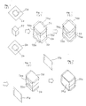
- Fig. 12 shows a procedure of packing of an article to be packed, and in this figure, at (a) is shown a state where wrapping materials 130 such as sheets and reinforcements 131a and 131b for the upper and lower surfaces were applied, at (b) is shown a state where side surface reinforcements 132 were applied, and at (c) is shown a state where a bundling belt 125 was applied only one. It is to be noted that illustration by chain lines at (c) represents that the article is bundled sequentially with bundling belts 125. At (d) is shown an appearance of a bundled package.
- Another object of the present invention is to provide an improved apparatus for bundling an article to be packed in which the above-described problems in the prior art are resolved.
- a method for compressive packing consisting of the steps of compressively shaping an article to be packed presenting a bulky tow-like state into a cubic or regular parallelepiped form, thereafter automatically wrapping the same from the above and the below by means of upper and lower wrapping materials having flexibility, then automatically applying reinforcements to all the outer surfaces thereof by making use of a reinforcement lifting device, a reinforcement elevator, a reinforcement feed truck and the like, and bundling the outer surfaces thereof with bundling belts.
- an apparatus for bundling an article to be packed in which reinforcement mounting devices disposed respectively on the head side and on the guide side of the apparatus are provided, the reinforcement mounting device is provided with a plurality of reinforcement holders so as to be able to advance and retreat at such locations that they may not become inphase with bundling belt guides, the reinforcements are automatically fed to the head side and the guide side of the bundling apparatus at a reinforcement feeding position and are transferred here to the reinforcement holders.
- the reinforcement holder is a vacuum suction pad.
- the reinforcement automatic mounting devices perform advancing operation to be pushed out towards the side surfaces of the article to be packed
- the bundling belt guides would stop with a little gap clearance left from the upper press seat and the lower press seat, and also the side surface reinforcements are urged against the side surfaces of the article to be packed via reinforcement holders such as vacuum suction pads.
- the reinforcement holders such as vacuum suction pads release the reinforcements, the bundling apparatus and the reinforcement automatic mounting devices both retreat and return to their original positions.
- the head side and the guide side of the bundling apparatus as well as the reinforcement automatic mounting devices move to the reinforcement feeding position (position B in Fig. 16), and here, side surface reinforcements are automatically fed to the reinforcement holders of the reinforcement automatic mounting devices of both the head side and the guide side by means of the reinforcement feeding device.
- the bundling apparatus according to the present invention, automation of the application of side surface reinforcements to an article to be packed can be achieved, hence workers can be released from dangerous works, thereby improvements in safety and reduction of labor can be realized, and appearance of packed packages is stabilized without being influenced by skill of workers. Also, a cycle time can be shortened and improvements in a productivity can be achieved.
- Figs. 1 to 9 illustrate the first preferred embodiment of the present invention
- Fig. 1 shows the successive steps in the packing work according to the present invention, which are carried out as described previously
- Fig. 2 shows feed timings of wrapping materials, reinforcements and bundling materials to principal units upon practicing the packing work according to the present invention, and an outline of the system.
- the present invention has been proposed in order to resolve the problems caused by mixing of foreign matters from the outside due to damage of wrapping materials or contamination by these foreign matters from a sanitary view point, and further the problems caused by biting of bundling belts into wrapping materials and tow resulted from a repulsive force of tow forming an article to be packed as is the case with a compressively packed bale, especially a packed bale of acetate tow or the like for use as tobacco filters; and the present invention relates to a method for carrying out completely automatically a series of working steps of compressively shaping tow, which is an article to be packed, into a predetermined height, thereafter wrapping the article with flexible wrapping materials such as a stuck or laminated material of polypropylene Hessian cloth and a polyethylene sheet or a stuck material of a polyethylene sheet and a kraft paper sheet, then applying the so-called reinforcements having larger strength and rigidity than the above-mentioned wrapping material such as
- Fig. 3 is a plan view showing a general layout of the apparatus used to practice the method according to the first preferred embodiment of the present invention
- Fig. 4 is a perspective view showing a portion X - X in Fig. 3.
- tow after tow has been stored in an enclosure box 1 in the preceding step of the process not shown, it is conveyed by conveyor means 51 to a center of a preliminary compression and transfer machine 52 in Fig. 3.
- the enclosure box 1 After the enclosure box 1 has been positioned at the center of the above-described tow transfer machine 52 by means of a positioning device not shown, it is lowered by an elevator 53, and further, a tow receiver 54 is opened in the illustrated manner by a tow receiver opening/closing device at the bottom of the enclosure box 1 not shown.
- a receiving seat in Fig. 4 Prior to this operation, a receiving seat in Fig. 4 is positioned at the top of a self-traveling type compression box 56 as penetrating therethrough. Accordingly, at the same time as "opening" completion of the tow receiver 54 at the bottom of the above-mentioned enclosure box 1, the tow 57 within the enclosure box 1 is transferred onto the receiving seat 55 via a fixed frame 58.
- the receiving seat 55 descends while supporting the tow 57, and it stops at a level somewhat higher than the tow receiver 58 at the bottom of the self-traveling type compression box 56 and holds this state.
- an upper press seat 59 descends and applies a pressure until the tow 57 within the enclosure box 1 is completely filled in the self-traveling type compression box 56.
- the receiving seat 55 descends and returns to the state shown in Fig. 6.
- the tow 57 within the self-traveling type compression box 56 is automatically transferred onto the tow receiver 58 associated with the self-traveling type compression box.
- the self-traveling type compression box 56 travels by itself along traveling rails 60a and 60b and comes to a main compression device 61, and here it is positioned at the center of the main compression device 61 by means of a positioning device not shown.
- the enclosure box 1 emptied at the center of the preliminary compression and tow transfer machine 52 is sent back to the installation of the preceding step by the conveyor device 51.
- the main compression device 61 is associated with an upper wrapping device 62 and a lower wrapping device 63, and before the above-mentioned self-traveling type compression box 56 enters the main compression device 61, the upper and lower reinforcements 5a and 5b and the upper and lower wrapping materials 6a and 6b have been automatically fed to these wrapping devices 62 and 63.
- a reinforcement feed truck 67 travels by itself and comes right under the reinforcement lifting device 65, and here it receives the reinforcement 5a (the upper reinforcement) lifted up by the above-mentioned reinforcement lifting device 65. Furthermore, it picks up one reinforcement 5b (the lower reinforcement). Thereafter the reinforcement feed truck 67 comes to the center of the main compression device 61 while holding the upper reinforcement 5a and the lower reinforcement 5b, here it feeds the upper reinforcement 5a to the upper wrapping device 62 and the lower reinforcement 5b to the lower wrapping device 63, and thereafter it returns to the state shown in Fig. 7. Then, continuously the lower wrapping material 6b is fed to the lower wrapping device 63 and the upper wrapping material 6a is fed to the upper wrapping device 62.
- the lower wrapping material 6b is drawn out from a wrapping material roll 68 by means of a drawing device 69, and after it has been cut into a length for one package, it is automatically fed to the lower wrapping device 63 by means of a wrapping material feeding device 70.
- the upper wrapping material 6a is drawn out from a wrapping material roll 71 by means of an upper wrapping material feeding device 72, and after it has been cut into a length for one package, it is fed to the upper wrapping device 62.
- the upper wrapping device 62 folds up the upper reinforcement 5a and the upper wrapping material 6a upwards as shown in Fig. 5 for the purpose of preparation for compressing tow within the self-traveling type compression box 56 in the next step of the process.
- FIG. 5 shows the state where the self-traveling type compression box 56 has come into the main compression device 61 and has been positioned under the above-described condition where the upper and lower reinforcements 5a and 5b and the upper and lower wrapping materials 6a and 6b were fed to the main compression device 61.
- the lower wrapping device 63 is raised by a hydraulic cylinder or the like up to the state where the lower wrapping material 6b closes the bottom of the self-traveling type compression box 56.
- the tow receiver 58 at the bottom of the self-traveling type compression box 56 is opened, and the tow is supported from the upper surface of a receiving seat 73 which forms one of constituent elements of the lower wrapping device 63, via the lower wrapping material 6b and the lower reinforcement 5b.
- an upper press seat 74 which forms one of constituent elements of the upper wrapping device 62 descends jointly with the upper reinforcement 5a and the upper wrapping material 6a, and compressively shapes the tow 57 within the self-traveling type compression box 56 with a predetermined compressing force up to a predetermined height.
- doors of the self-traveling type compression box 56 are automatically opened, and the self-traveling type compression box 56 travels by itself from the center of the main compression device 61 towards the preliminary compression and tow transfer device 52 and restores to its original state. Accordingly, in the preliminary compression and tow transfer device 52, transfer of tow from the subsequent enclosure box 1 to the self-traveling type compression box 56 is automatically carried out in succession as described previously.
- the tow 57 after completion of main compression is automatically wrapped by the lower wrapping device 63 and the upper wrapping device 62 in the sequence of wrapping of the lower portion and then wrapping of the upper portion as shown in Figs. 1(b) and 1(c), starting from the state shown in Fig. 6. It is to be noted that while the sequence of wrapping of the lower portion and then wrapping of the upper portion was chosen in the illustrated embodiment, in some cases the wrapping could be done through the prior art method in the sequence of wrapping of the upper portion and then wrapping of the lower portion.
- ears 74a, 74b, 75a and 75b of the upper and lower reinforcements 5a and 5b are folded in the illustrated manner by means of the upper wrapping device 62 and the lower wrapping device 63. It is to be noted that these ears serve to prevent the bundling belts 20 such as bands, wires or the like from biting into the reinforcements.
- the side surface reinforcements 19a and 19b are stacked by a necessary number in stockers 76a and 76b, respectively, and they are automatically fed by reinforcement feeding devices 77a and 77b to a band (or wire) applying device 78 one by one when the band applying device 78 is present at a home position or standby position 78H, and to a band (or wire) guiding device 79 one by one when the band guiding device 79 is present at a home position or standby position 79H.
- the band (or wire) applying device 78 and the band (or wire) guiding device 79 would move automatically as accompanied by the side surface reinforcements 19a and 19b up to the positions of the band applying device 78 and the band guiding device 79 in Figs. 3 and 8, and further at the respective end points of movement they would move respectively towards the center of the main compression device 61 and would urge the side surface reinforcements 19a and 19b against the side surfaces of the tow block as shown in Fig. 1(e).
- bundling with bundling belts 20 such as bands or wires is carried out sequentially by the band (or wire) applying device 78 as shown in Fig. 1(f) by making use of band (or wire) guides provided within the upper press seat 74 associated with the upper wrapping device 62 and within the receiving seat 73 associated with the lower wrapping device 63.
- the band (or wire) applying device 78 returns to its standby position 78H shown in Fig. 3.
- a bale take-out conveyor 80 To the band (or wire) applying device 78 is interlocked a bale take-out conveyor 80, and accordingly, when the band (or wire) applying device 78 occupies the standby position 78H, as interlocked therewith the conveyor 80 advances up to the line connecting the preliminary compression and tow transfer device 52 and the center of the main compression device 61.
- the upper press seat 74 including the upper wrapping device 62 releases the compressing force applied to the tow block, and also it rises for the purpose of preparation for taking out the bale, which has completed a packing work up to the state shown in Fig. 1(f), from the main compression device 61 onto the bale take-out conveyor 80.
- the band (or wire) guiding device 79 is associated with a bale push-out machine 81.
- the bale take-out conveyor 80 advances towards the main compression device 61 in order to receive a bale.
- the packed bale is pushed out onto the bale take-out conveyor 80 by the bale push-out machine 81.
- the packed bale comes to the bundling machine 84, via the bale take-out conveyor 80, a traverser 82 and a bale transport conveyor 83.
- To the bundling machine 84 have been preliminarily fed end surface reinforcements 21a and 21b from end surface reinforcement stockers 86a and 86b by means of reinforcement feeding devices 86a and 86b, respectively, as shown in Fig. 1(g).
- positioning of the bale is effected by means of a bale positioning device not shown, and subsequently, end surface reinforcements 21a and 21b are applied to the end surfaces 87a and 87b of the bale.
- bands (or wires) 88 are applied to the bale by the bundling machine, thereby the end surface reinforcements 21a and 21b are fixed to the bale end surfaces 87a and 87b and also expansion of the bale is constrained.
- the ears of the upper and lower reinforcements 5a and 5b of the packed bale are folded by well-known folding guides and folding machines not shown in the midway of the transport by the bale transport conveyor 83, the ears of the upper reinforcement 5a being folded downwards, while those of the lower reinforcement 5b being folded upwards, and thus they are dealt with so that the ears may not become obstacles when the end surface reinforcements 21a and 21b are applied.
- the packed bale is conveyed by the bale transport conveyor 83 and comes to a horizontal bundling device 89.
- the ears of the reinforcements 19a and 19b (90a and 90b: there are two ears at the opposite ends of each reinforcement 19a or 19b) are folded as shown in Fig. 1(h) by means of a ear folding device assembled in the horizontal bundling device 89 but not shown, and subsequently, a bundling portion 91 of the bundling device 89 shown in Fig. 9 descends, and sequentially performs application of bands (or wires) 22 as shown in Fig. 1(i) to make the ears 90a and 90b of the reinforcements 19a and 19b butt against the end surfaces of the packed bale for confining them.
- reference numeral 133 designates a compressive packing machine main body, within this compressive packing machine main body 133, tow or the like is compressed by a cylinder 134 via an upper press seat 122a and a lower press seat 122b to form an article 123 to be packed, and also it is automatically wrapped with a wrapping material 130 by means of a lower wrapping device 136 and an upper wrapping device 135. It is to be noted that to the upper and lower surfaces of the article 123 to be packed are mounted reinforcements 131a and 131b by the means described above in connection to the first preferred embodiment.
- the article 123 to be packed which was wrapped with the wrapping material 130 is bundled after bundling belts 125 have been applied thereto through a series of operations of a head side 102 and a guide side 103 of a bundling apparatus 101, which correspond to the band applying device 78 and the band guiding device 79, respectively, in the first preferred embodiment.
- the apparatus according to the second preferred embodiment of the present invention is characterized in that a reinforcement mounting device 137 for automatically mounting side surface reinforcements 132 prior to the bundling step, is additionally provided in the above-mentioned bundling apparatus 101.
- holding frames 138 are provided vertically on the opposite sides of the front portion of the upper surface of a table 107, mount members 139 of a reinforcement holding mechanism are mounted to the same frames 138 via slide mechanisms 140 consisting of guides and the like, in the same mount member 139 are disposed a plurality of (four, in the illustrated embodiment) reinforcement holders such as vacuum suction pads or the like (since the reinforcement could be held by acicular members, the holder should not be limited to a vacuum suction pad), the side surface reinforcement 132 such as a corrugated cardboard sheet is held by suction by means of the holder, and the mount member 139 is adapted to perform advancing and retreating operations so as not to interfere with the bundling belt guides 108a, as driven by cylinders 142.
- rails 146 are laid, a movable frame 105 is provided with rollers, and the same frame 105 is laterally movable along the rails
- a mount member 139 is mounted to a frame 119 via a slide mechanism 140, reinforcement holders such as vacuum suction pads 141 or the like are disposed so that they can advance and retreat as driven by a cylinder 142 in such manner that they may not interfere with bundling belt guides 108b similarly to the above-described.
- reinforcement holders such as vacuum suction pads 141 or the like are disposed so that they can advance and retreat as driven by a cylinder 142 in such manner that they may not interfere with bundling belt guides 108b similarly to the above-described.
- rails 144 are laid, the movable frame 105 is provided with rollers, so that the same frame 145 is laterally movable along the rails 144 between position A and position B as driven by a cylinder 143.
- the head side 102 is normally present at the standby position B, and under this condition, a reinforcement is fed to the reinforcement mounting device 137 by means of a reinforcement feeding device not shown. Then, the vacuum suction pads 141 advance as driven by the cylinder 142, receive the side surface reinforcement 132 from the reinforcement feeding device by sucking it, and retreat, and under this condition they stand by. Likewise, the guide side 103 is also normally present at the standby position B, and under this condition, a reinforcement is fed to the reinforcement mounting device 137 by means of a reinforcement feeding device not shown. At this time, the vacuum suction pads 141 advance as driven by the cylinder 142, receive the side surface reinforcement 132 from the reinforcement feeding device by sucking it, and retreat, and under this condition they stand by.
- the head side 102 moves jointly with the movable frame 105 as driven by the cylinder 104, further it moves up to position A via the table 107 as driven by the cylinder 106, also the guide side 103 moves jointly with the movable frame 145 as driven by the cylinder 143, further it moves up to position A via the table 118 as driven by the cylinder 117, and they push out the bundling belt guides 108a and 108b up to the positions 108a′ and 108b′ where small gap clearances are left between these guides and the upper and lower press seats 122a and 122b, respectively. Since the vacuum suction pads 141 holding the side surface reinforcements 132 also advance as a result of this operation, the side surface reinforcements 132 are also automatically urged against the side surfaces of the article 132 to be packed.
- the bundling machine 110 advances a little, thereafter it moves laterally up to the next bundling belt guide position, and advances a little to continue bundling.
- the article 132 is bundled sequentially by the bundling belts 125 one by one.
- the vacuum suction pads 141 of the both sides release the vacuum pressure. (It is to be noted that the vacuum pressure could be released immediately after the side surface reinforcements 132 have been urged against the article 123 to be packed.)
- the head side 102 retreats as driven by the cylinder 106, the bale take-out conveyor 112 is moved up to position A via the movable frame 105 by the cylinder 104, then the head side 102 moves to position B as interlocked, and receives feed of the side surface reinforcement 132 in the above-described manner.
- the bale take-out conveyor 112 is pushed out against the side surface of the packed article after bundling (completed bale) via the table 113 by the cylinder 114, the completed bale is pushed out by the bale push-out pusher 120a and 120b provided in the guide side 103, and is taken out while being loaded on the above-mentioned conveyor 112.
- the guide side 103 moves up to position B via the movable frame 145 as driven by the cylinder 143, and receives feeding of the side surface reinforcement 132. Subsequently, similar operations are automatically repeated.
- the method for compressive packing according to the present invention since the method for compressive packing according to the present invention has the characteristic feature, there is no need to preliminarily combine a reinforcement and a wrapping material set by set as is the case with the prior art method, hence human labor saving can be achieved, and also it is unnecessary to reserve a space for temporary storage. Also, according to the present invention, since a compressive packing work is carried out automatically, persons can be released from a simple labor of the packing work and also released from a dangerous work, and moreover, a productivity can be improved by shortening a total cycle time necessitated for packing of one package.
- the bundling apparatus according to the present invention is used for practicing the novel compressive packing method, since the apparatus is constructed as described above in detail, automation of the application of side surface reinforcements to an article to be packed can be achieved, hence workers can be released from dangerous works, thereby improvements in safety and reduction of labor can be achieved, and appearance of packed packages is stabilized without being influenced by skill of workers. Also, a cycle time can be shortened and improvements in a productivity can be achieved.
Landscapes
- Engineering & Computer Science (AREA)
- Mechanical Engineering (AREA)
- Basic Packing Technique (AREA)
Applications Claiming Priority (4)
| Application Number | Priority Date | Filing Date | Title |
|---|---|---|---|
| JP254864/89 | 1989-09-29 | ||
| JP25486489A JPH03124518A (ja) | 1989-09-29 | 1989-09-29 | 圧縮梱包方法 |
| JP1989127915U JP2516741Y2 (ja) | 1989-11-02 | 1989-11-02 | 被梱包物結束装置 |
| JP127915/89U | 1989-11-02 |
Publications (2)
| Publication Number | Publication Date |
|---|---|
| EP0420071A1 true EP0420071A1 (de) | 1991-04-03 |
| EP0420071B1 EP0420071B1 (de) | 1994-06-08 |
Family
ID=26463744
Family Applications (1)
| Application Number | Title | Priority Date | Filing Date |
|---|---|---|---|
| EP90118222A Expired - Lifetime EP0420071B1 (de) | 1989-09-29 | 1990-09-21 | Verfahren zum Verpacken durch Zusammenpressen und Vorrichtung zum Bündeln von zu verpackenden Produkten |
Country Status (3)
| Country | Link |
|---|---|
| US (1) | US5131210A (de) |
| EP (1) | EP0420071B1 (de) |
| DE (1) | DE69009648T2 (de) |
Cited By (2)
| Publication number | Priority date | Publication date | Assignee | Title |
|---|---|---|---|---|
| WO2007001810A1 (en) * | 2005-06-20 | 2007-01-04 | Eastman Chemical Company | Packages, packaging systems, methods for packaging, and apparatuses for packaging |
| US7306093B2 (en) | 2003-02-14 | 2007-12-11 | Eastman Chemical Company | Packages, packaging systems, methods for packaging and apparatus for packaging |
Families Citing this family (22)
| Publication number | Priority date | Publication date | Assignee | Title |
|---|---|---|---|---|
| DE4015642A1 (de) * | 1990-05-15 | 1991-11-21 | Autefa Maschinenfab | Verfahren und vorrichtung zum umschlagen einer deckfolie um einen pressballen |
| US5224911A (en) * | 1992-01-17 | 1993-07-06 | Tien Pao Liem | Bale encasing and de-casing system |
| DE20104960U1 (de) * | 2001-03-21 | 2003-05-15 | AUTEFA Automation GmbH, 86316 Friedberg | Verpackungseinrichtung und verpackter Pressballen |
| ITFI20010135A1 (it) * | 2001-07-13 | 2003-01-13 | Gualchierani Textile Automatio | Pressa per la formazione di balle di materiale tessile od altro,con dispositivo di rivestimento mediante un telo |
| US20050121348A1 (en) * | 2003-12-09 | 2005-06-09 | Clare Timothy P. | Package insert and stackable package for articles |
| US7775351B2 (en) * | 2004-05-28 | 2010-08-17 | Hbi Branded Apparel Enterprises, Llc | System and method for packaging apparel |
| US7784399B2 (en) * | 2004-10-11 | 2010-08-31 | Paper And Plastic Partnership, Llc | Method and process of collecting, packaging and processing recyclable waste |
| US20090148629A1 (en) * | 2005-06-24 | 2009-06-11 | Sasine John K | Systems, methods, and devices for collecting, packaging, and processing recyclable waste |
| US20090029074A1 (en) | 2004-10-11 | 2009-01-29 | John Sasine | Method and process for collecting and processing recyclable waste |
| US7520007B2 (en) * | 2004-11-10 | 2009-04-21 | Allen Medical Systems, Inc. | Accessory rail clamp with latch and lock mechanisms |
| US7730832B2 (en) | 2005-04-28 | 2010-06-08 | Eastman Chemical Company | Method and apparatus for forming a bale having substantially flat upper and lower surfaces |
| US7540126B2 (en) * | 2006-04-19 | 2009-06-02 | Hbi Branded Apparel Enterprises, Llc | System and method for compactly packaging apparel |
| EP2910477B1 (de) * | 2014-02-21 | 2018-03-28 | Celanese Acetate LLC | Verfahren zum Verpacken von faserigen Materialien |
| US10287048B2 (en) * | 2014-10-16 | 2019-05-14 | Neopost Technologies | System and method for automatically packaging items varying in size and number for shipment |
| US20180141700A1 (en) * | 2015-05-26 | 2018-05-24 | Sealed Air Corporation (Us) | Packaging Assembly |
| EP3284686B1 (de) * | 2016-08-16 | 2018-12-26 | Neopost Technologies | Vorrichtung und verfahren zur anordnung von artikeln für den versand |
| DE202017104766U1 (de) | 2017-08-09 | 2018-11-12 | Autefa Solutions Germany Gmbh | Verpackungseinrichtung |
| DE202019105299U1 (de) * | 2019-09-25 | 2021-01-08 | Autefa Solutions Germany Gmbh | Pressballen, Verpackungseinrichtung und Produktionseinrichtung für Pressballen |
| CN111891508A (zh) * | 2020-07-13 | 2020-11-06 | 海盐通用机械塑料包装厂 | 一种蓬松产品打包机 |
| CN114735270B (zh) * | 2022-04-19 | 2023-07-28 | 青岛中城嘉业工程有限公司 | 一种建筑用钢筋打捆给料装置 |
| CN119551282B (zh) * | 2024-12-27 | 2025-07-22 | 深圳市智佳能自动化有限公司 | 一种烟草输送机 |
| CN119929245A (zh) * | 2025-03-20 | 2025-05-06 | 上海邯祥机电成套设备有限公司 | 一种长丝束打包机 |
Citations (3)
| Publication number | Priority date | Publication date | Assignee | Title |
|---|---|---|---|---|
| FR724456A (fr) * | 1931-09-03 | 1932-04-27 | Torfstreuverband Gmbh | Procédé pour la confection et l'étiquetage des balles de tourbe |
| US1922046A (en) * | 1929-07-03 | 1933-08-15 | Brown Co | Bale covering and method of preparing same |
| EP0029977A1 (de) * | 1979-11-30 | 1981-06-10 | Hoechst Aktiengesellschaft | Verfahren und Vorrichtung zum Pressen, Verpacken und Umreifen von faserigem Gut in Ballenform |
Family Cites Families (10)
| Publication number | Priority date | Publication date | Assignee | Title |
|---|---|---|---|---|
| US3500609A (en) * | 1963-10-03 | 1970-03-17 | Signet Packaging Enterprises L | Means for packaging cuboid containers |
| US3962846A (en) * | 1974-01-28 | 1976-06-15 | Hardwicke-Etter Company | Apparatus for automatic wrapping of bales |
| DE2911958C2 (de) * | 1979-03-27 | 1993-10-07 | Hoechst Ag | Verfahren zum Verpacken von faserigem Gut in Ballen sowie geeignete Preßanordnung dazu |
| US4407107A (en) * | 1980-09-11 | 1983-10-04 | Hergeth, Incorporated | Horizontal baling apparatus and method |
| US4360997A (en) * | 1980-09-11 | 1982-11-30 | Hergeth, Incorporated | Baling apparatus and method |
| GB8613760D0 (en) * | 1986-06-06 | 1986-07-09 | Fiberglas Canada Inc | Packaging compressible items |
| ES2030790T3 (es) * | 1987-06-10 | 1992-11-16 | Autefa Maschinenfabrik Gmbh | Procedimiento y dispositivo para el embalaje de pacas prensadas. |
| DE3732390A1 (de) * | 1987-09-25 | 1989-04-06 | Fleissner Maschf Ag | Faserballenpresse |
| DE3732376A1 (de) * | 1987-09-25 | 1989-04-06 | Fleissner Maschf Ag | Verfahren zum verpacken von faserigem gut in ballen sowie geeignete faserballenpresse dazu |
| US4805383A (en) * | 1988-01-11 | 1989-02-21 | Manville Corporation | Batt packaging machine and method |
-
1990
- 1990-09-21 EP EP90118222A patent/EP0420071B1/de not_active Expired - Lifetime
- 1990-09-21 DE DE69009648T patent/DE69009648T2/de not_active Expired - Fee Related
-
1991
- 1991-07-23 US US07/735,147 patent/US5131210A/en not_active Expired - Fee Related
Patent Citations (3)
| Publication number | Priority date | Publication date | Assignee | Title |
|---|---|---|---|---|
| US1922046A (en) * | 1929-07-03 | 1933-08-15 | Brown Co | Bale covering and method of preparing same |
| FR724456A (fr) * | 1931-09-03 | 1932-04-27 | Torfstreuverband Gmbh | Procédé pour la confection et l'étiquetage des balles de tourbe |
| EP0029977A1 (de) * | 1979-11-30 | 1981-06-10 | Hoechst Aktiengesellschaft | Verfahren und Vorrichtung zum Pressen, Verpacken und Umreifen von faserigem Gut in Ballenform |
Cited By (6)
| Publication number | Priority date | Publication date | Assignee | Title |
|---|---|---|---|---|
| US7306093B2 (en) | 2003-02-14 | 2007-12-11 | Eastman Chemical Company | Packages, packaging systems, methods for packaging and apparatus for packaging |
| US7739857B2 (en) | 2003-02-14 | 2010-06-22 | Eastman Chemical Company | Packages, packaging systems, methods for packaging and apparatus for packaging |
| US7958696B2 (en) | 2003-02-14 | 2011-06-14 | Eastman Chemical Company | Packages, packaging systems, methods for packaging and apparatus for packaging |
| US8671652B2 (en) | 2003-02-14 | 2014-03-18 | Eastman Chemical Company | Packages, packaging systems, methods for packaging and apparatus for packaging |
| US9598184B2 (en) | 2003-02-14 | 2017-03-21 | Eastman Chemical Company | Method for packaging fiber material |
| WO2007001810A1 (en) * | 2005-06-20 | 2007-01-04 | Eastman Chemical Company | Packages, packaging systems, methods for packaging, and apparatuses for packaging |
Also Published As
| Publication number | Publication date |
|---|---|
| EP0420071B1 (de) | 1994-06-08 |
| DE69009648T2 (de) | 1994-11-17 |
| US5131210A (en) | 1992-07-21 |
| DE69009648D1 (de) | 1994-07-14 |
Similar Documents
| Publication | Publication Date | Title |
|---|---|---|
| EP0420071B1 (de) | Verfahren zum Verpacken durch Zusammenpressen und Vorrichtung zum Bündeln von zu verpackenden Produkten | |
| US4318264A (en) | Process and apparatus for the packaging of fibrous material in bales | |
| EP0029977B1 (de) | Verfahren und Vorrichtung zum Pressen, Verpacken und Umreifen von faserigem Gut in Ballenform | |
| EP2134608B1 (de) | Verpackungseinrichtung und verpackungsverfahren | |
| EP2750975B1 (de) | Verpackungseinrichtung für pressballen mit einer transportvorrichtung | |
| US4805383A (en) | Batt packaging machine and method | |
| EP2258618B1 (de) | Vorrichtung und Verfahren zum Herstellen einer Verpackungseinheit | |
| US6481186B2 (en) | Apparatus for forming a packaging arrangement | |
| CN115043052B (zh) | 一种套袋烟梗自动开箱系统及其方法 | |
| JP2659861B2 (ja) | プレスベールを包装する方法及び装置 | |
| JPH04242513A (ja) | 繊維状物質をこりに梱包するための方法 | |
| JP3522891B2 (ja) | ひと重ねの段ボール紙など特に圧縮可能な梱包物を結束するための装置 | |
| EP3665086B1 (de) | Verpackungseinrichtung und verpackungsverfahren | |
| CH698909B1 (de) | Vorrichtung und Verfahren zum Paketieren von Faserband, insbesondere von Baumwollfaserband. | |
| EP0695690B1 (de) | Verfahren und Vorrichtung zum Verpressen und Verpacken von faserigem Gut in Ballen | |
| JPH03124518A (ja) | 圧縮梱包方法 | |
| EP0441753A1 (de) | Vorrichtung zum Pressen und Verpacken von Ballen | |
| DE2135281A1 (de) | Vorrichtung zum verpacken von flachen warenpackungen zu sammelpackungen | |
| DE19945386A1 (de) | Verfahren und Vorrichtung zum Verpacken von Rollenware, insbesondere Wickelrollen aus Kunststofffolie | |
| JP2516741Y2 (ja) | 被梱包物結束装置 | |
| CN118723215A (zh) | 一种打包机 | |
| WO2012072092A1 (de) | Vorrichtung und verfahren zum herstellen einer verpackungseinheit | |
| EP0405488A1 (de) | Verpackungsanlage für Kurzschnittfasern in Kleingebinden | |
| DE7102897U (de) | Vorrichtung zum Verpacken von flachen Warenpackungen zu Sammelpackungen | |
| JPH08230828A (ja) | 梱包機におけるシート供給装置 |
Legal Events
| Date | Code | Title | Description |
|---|---|---|---|
| PUAI | Public reference made under article 153(3) epc to a published international application that has entered the european phase |
Free format text: ORIGINAL CODE: 0009012 |
|
| 17P | Request for examination filed |
Effective date: 19901018 |
|
| AK | Designated contracting states |
Kind code of ref document: A1 Designated state(s): DE IT |
|
| 17Q | First examination report despatched |
Effective date: 19930202 |
|
| GRAA | (expected) grant |
Free format text: ORIGINAL CODE: 0009210 |
|
| AK | Designated contracting states |
Kind code of ref document: B1 Designated state(s): DE IT |
|
| REF | Corresponds to: |
Ref document number: 69009648 Country of ref document: DE Date of ref document: 19940714 |
|
| ITF | It: translation for a ep patent filed | ||
| PLBE | No opposition filed within time limit |
Free format text: ORIGINAL CODE: 0009261 |
|
| STAA | Information on the status of an ep patent application or granted ep patent |
Free format text: STATUS: NO OPPOSITION FILED WITHIN TIME LIMIT |
|
| 26N | No opposition filed | ||
| PGFP | Annual fee paid to national office [announced via postgrant information from national office to epo] |
Ref country code: DE Payment date: 19950928 Year of fee payment: 6 |
|
| PG25 | Lapsed in a contracting state [announced via postgrant information from national office to epo] |
Ref country code: DE Effective date: 19970603 |
|
| PG25 | Lapsed in a contracting state [announced via postgrant information from national office to epo] |
Ref country code: IT Free format text: LAPSE BECAUSE OF NON-PAYMENT OF DUE FEES;WARNING: LAPSES OF ITALIAN PATENTS WITH EFFECTIVE DATE BEFORE 2007 MAY HAVE OCCURRED AT ANY TIME BEFORE 2007. THE CORRECT EFFECTIVE DATE MAY BE DIFFERENT FROM THE ONE RECORDED. Effective date: 20050921 |