EP0420110B1 - Befeuchtigungsvorrichtung für Gegenstände, als Teil einer Einrichtung und ihre Anwendung - Google Patents
Befeuchtigungsvorrichtung für Gegenstände, als Teil einer Einrichtung und ihre Anwendung Download PDFInfo
- Publication number
- EP0420110B1 EP0420110B1 EP90118317A EP90118317A EP0420110B1 EP 0420110 B1 EP0420110 B1 EP 0420110B1 EP 90118317 A EP90118317 A EP 90118317A EP 90118317 A EP90118317 A EP 90118317A EP 0420110 B1 EP0420110 B1 EP 0420110B1
- Authority
- EP
- European Patent Office
- Prior art keywords
- moistening
- reservoir
- path
- compartments
- wetting
- Prior art date
- Legal status (The legal status is an assumption and is not a legal conclusion. Google has not performed a legal analysis and makes no representation as to the accuracy of the status listed.)
- Expired - Lifetime
Links
Images


Classifications
-
- B—PERFORMING OPERATIONS; TRANSPORTING
- B43—WRITING OR DRAWING IMPLEMENTS; BUREAU ACCESSORIES
- B43M—BUREAU ACCESSORIES NOT OTHERWISE PROVIDED FOR
- B43M5/00—Devices for closing envelopes
- B43M5/04—Devices for closing envelopes automatic
- B43M5/042—Devices for closing envelopes automatic for envelopes with only one flap
Definitions
- the present invention relates to a set for wetting articles and in particular envelope flaps for automatic mail processing installations.
- such a wetting assembly essentially comprises a wetting element supplied directly or indirectly from a water reserve tank which carries it or not, against which rubs the flap of successive envelopes driven on a path.
- the wetting element must be supplied with enough, but not excess, to allow a fair transfer of water on the flap rubbing against it.
- the means ensuring its supply, from the water in the tank, and the tank itself must avoid causing possible splashes, under the effect of possible vibrations in the installation or during their assembly or disassembly in the 'installation.
- water reserve tank is mounted at a distance from the wetting element and therefore from the path followed by the envelopes and their flaps.
- Document FR-A-2 195 532 describes an embodiment of such a device for wetting and folding the envelope flaps.
- the device comprises a water tank, a wick support arm which is inclined at an angle at the top of the tank and a wick, one end of which is in the tank and the other is mounted on a wick holder and passes through the wick support arm.
- This wick support arm has an elongated marginal portion which releases an elongated portion of the wick, through an open elongated portion of the wick holder.
- This wick holder is of J-section, with projections which penetrate into the wick to lock it in place and is placed in the wick support arm to which it is adapted.
- This mooring assembly is mounted under a platform, with the clear portion of the wick located substantially under one of the edges of the platform. It is associated with an upstream deflector which receives the flap freely projecting over the edge of the platform, on which the body of the envelope is driven, and the guide below the lower edge of the wick support arm.
- a folding assembly of complex shape then ensures folding of the flap, by firmly pushing its gummed region against the wick.
- the object of the present invention is to provide a wetting assembly of clearly simplified design and operation, which also has a small footprint in a mail processing installation, poses no problem of assembly or disassembly in the installation and avoids possible splashes.
- a set for wetting articles comprising a wetting element and a supply tank for said wetting element, said element being mounted on said tank and having a protruding part for wetting each article traveling on a path and applied against it, characterized in that said tank is mounted, with said wetting element which it carries, transverse to the path, directly below it and substantially over its entire width, and comprises a series of partitions dividing it across the width of the path in compartments independent of each other, ensuring the individual supply of said wetting element.
- said tank is constituted by an elongated and narrow tank, of length substantially equal to the width of the path and with said partitions extending over its height and width, and has its upper face closed by a cover and crossed by said wetting element.
- said wetting element is constituted by a flat element mounted on an element holder which retains it on the cover and in the tank.
- said cover comprises a base, covering said tank and surmounted by at least one chimney for receiving and holding the wetting element, with said element holder, in each of the compartments of the tank.
- said base is further equipped with a compartment feed chute, formed on one side of the chimney.
- Said chute has on the base a series of holes opening into the respective compartments and closed by a strip of plugs.
- the present invention also relates to a wetting device comprising said wetting assembly and an associated wetting deflector, mounted on either side of the path of the articles, characterized in that it further comprises a sliding bar pivotally mounted on said tank and extending, in front of said wetting element, for the direction of advance of the articles, and controlled between a protective position, for which it is adjacent to the projecting part of the element wetting and flush substantially on the level of the path, and an erasing position, for which it is recessed below the projecting part of the wetting element and below the level of the path.
- the deflector and the bar are coupled by means coming laterally on the path, for their simultaneous control.
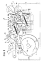
- FIG 1 there is illustrated a mail processing machine comprising a wetting device 1 of the envelope flap, which is equipped in accordance with the present invention.
- This wetting device 1 is mounted on an envelope path 2 of the machine, on which the envelopes are driven flat.
- Two pairs of sets of rollers 3A, 3B and 4A, 4B, between which is the wetting device 1, define the path 2 and ensure the drive of the envelopes.
- the arrow 2A indicates the advance of the envelopes on the way.
- the general organization of the machine is as such known. It is briefly described below.
- the pair of roller sets 3A, 3B belongs to a device 3 for loading envelopes or alternatively can receive the envelopes already loaded. It ensures with the pair of roller sets 4A, 4B, in particular the advance of the envelopes loaded on the way, whose unfolded flap is flat and at the rear of the envelope body in the wetting device.
- the pair of rollers 4A, 4B also constitutes a device 4 for ejecting the envelopes from the path 2.
- a closing device 5 for the envelopes is mounted between the wetting device 1 and the ejection device 4.
- This closing device 5 comprises a pair of pressing elements 5A, 5B.
- the elements 5A and 5B are elastically stressed under pressure one above the other and are mounted on the same pair of articulated arms 6.
- the upper element 5A is a roller, the lower element is a section of elongated section.
- This pair of pressing elements 5A, 5B is made to pivot opposite path 2 according to arrow 6A, from a rest position, shown in FIG. 1 and for which it is external to the path, in a so-called closed position, for which it is interposed on the path, with its elements on either side of the path.
- a pair of closing cams 7 controls and maintains it in one or other of its two positions.
- a roller 6B carried by each arm 6 comes under pressure on the corresponding closing cam.
- Each cam 7 has on its periphery a section 7A assigned to setting and maintaining the pair of pressing elements in the rest position and a section 7B assigned to setting and keeping it in the closed position.
- the wetting device 1 makes it possible to wet or not to wet the flaps which pass through it, depending on whether the closing of the envelopes is desired or not.
- the closure of each envelope is ensured in two stages by the pair of pressing elements 5A, 5B placed in the closed position, when the previously wet flap reaches its level.
- the flap receives a first fold substantially at 90 ° on the body of the envelope.
- the envelope is driven in the opposite direction, for its retreat on the way, its flap then passes between the pair of pressing elements and is folded completely on the envelope body, for its sealing.
- a new reversal of the drive of the envelope on the way ensures its ejection out of the way, by the pair of rollers 4A, 4B.
- the flap of each envelope passes through the wetting device without being wet, then passes under the pair of pressing elements 5A, 5B maintained in the rest position. It is then directly ejected, without the step of retreating on path 2.
- the wetting device 1 comprises a wetting assembly 1A, mounted under the path 2 and an associated wetting deflector 1B mounted above the path.
- the wetting assembly 1A comprises a wetting element 10, mounted in a water reserve tank 11.
- the wetting element 10 is carried by a support 12 which ensures its retention on the tank; it soaks in water for its food and protrudes above the tank.
- the tank 11 is closed by a cover 13, which passes through the wetting element.
- a series of fins 13A from the cover 13 extends over one of the edges of the wetting element, called the rear edge for the direction of advance on the path 2 given by the arrow 2A.
- This tank 11 is of particular embodiment to form with the wetting element 10 that it carries the wetting assembly 1A in accordance with the present invention. It is described in detail below.
- the wetting device 1 represented in FIG. 1 is, for its part, of general organization in accordance with that described in the patent application "selective wetting device for envelope flap", having the same filing date, of the applicant . A more brief description of this device is incorporated below.
- the wetting assembly 1A is mounted transversely under the path 2, the wetting element 10 remaining slightly recessed under the path while the vertical fins 13A are flush with the level of the path. It is directly mounted between a pair of lower flanges, such as the primed flange 8, of the machine.
- the tray 11 has two projecting fingers 14A, 14B on each of its small lateral faces, substantially at an upper corner and at the opposite lower corner.
- Each flange 8 has in correspondence, a rectangular notch 8A, in which an attached support part 9 comes laterally to define two retaining housings 9A, 9B for the two projecting fingers 14A, 14B.
- the container 11 is directly mounted and retained without play in place between the flanges, by tilting it to insert each lower protruding finger into its retaining housing, then bringing it back to the horizontal to slide each upper finger at the same time into its retaining housing. It can be removed just as easily.
- This mooring assembly 1A further comprises a strip sliding 15, pivoting and associated with the wetting element 10. It extends over the front of the wetting element and has a substantially flat face called sliding face 15B for the envelopes. It is also advantageously carried by the tank 11 by being pivoted at the front of the wetting element 10. It is mounted at the end of a pair of arms 16, these arms come to extend externally on the small lateral faces of the tray 11 where each of them is articulated on the projecting finger 14A. A spring 17, fixed to each arm 16 and anchored on the corresponding small side face of the tray, ensures the elastic retention of the sliding bar in a high rest position from which it is actuated according to arrow 15A in a low erased position .
- This high position is just in front of the wetting element, with its sliding face 15B projecting slightly above the wetting element to be in the plane of the path 2.
- This high rest position is said to be protective position, for which the slide bar prevents contact of the envelope flap with wetting element.
- a stud 18A on each small side face of the tray forms a stop for the arm 16 for the high rest position of the bar.
- another stud 18B on each small lateral face of the tray forms an abutment stop for the arm 16 for the low position of the bar.
- This erased low position is also called the wetting position for which the envelope flap comes into contact with the wetting element.
- the bar has drooping lips 15C, not continuous on its front edge. It also has its end portions 15D, in a semi-round shape, which protrude above the sliding face 15B and extend laterally on path 2.
- the wetting deflector 1B is adapted to cooperate with the wetting element 10 and the sliding bar 15. It comprises an actual deflector 20.
- the deflector 20 extends above the path 2, over its width, and comes slightly in front of the mooring element. It is carried at the end of a pair of arms 21, articulated on an intermediate axis 21A and controlled opposite the deflector by a pair of wetting cams 22.
- a roller 21B carried by each arm 21 ensures the coupling between the pair of arms and the pair of wetting cams.
- This pair of cams 22 and the pair of closing cams 7 are set relatively to each other on the same drive motor shaft 23.
- the arrow 23A translates the direction of rotation of this shaft.
- a profile 22A is assigned to maintaining the deflector in the high rest position and a second profile 22B for keeping it in the low wetting position.
- the arrow 20A translates the control of the deflector in the low position. In the rest position the deflector remains at a distance above the path. In the low position, it comes to interfere with the plane of the path, in front of the anchoring element.
- the arms 21 are each in two parts, one being a control lever 24 and the other a support 25 of the deflector.
- the lever and the support are both articulated in 21A; they are also coupled by a spring 26. This spring maintains a rib 25D, provided on the support, against a ramp 24A defined for it on the lever.
- This simultaneous control is carried out by the pair of wetting cams 22 and means for coupling the deflector 20 or its arms 21 with the sliding bar 15 or its arms 16.
- the coupling means illustrated are defined by the profile of the terminal edge lower 25D of each of the supports 25 of the deflector, which constitutes a pressing element, and by the corresponding semi-circular terminal shoulder 15D of the sliding bar 15, which constitutes a bearing stop for the pressing element.
- the spring 17 ensures the return of the sliding bar in the high rest position when the deflector 20 returns to the high rest position.
- the wetting element 10 is constituted by a flat element mounted vertically in the tank. It’s for example a flat felt, a flat sponge, a flat brush, or the like. It is carried by its support 12, also flat, called the element holder, one of its large faces being attached to one of the faces of the element holder. Its mounting on the tank is specified during the description of the wetting assembly 1A, made with reference to the following figures.
- this wetting assembly further includes a plug strip 19 adapted to the cover 13 and allowing the filling of the tank 11 and its closure after filling.
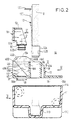
- the container 11 is described with reference to FIGS. 2 and 3.
- the container is elongated and of relatively small width; it constitutes a water tank with a substantially parallelepiped section. It spans the width of the path.
- Its open upper face has a small rib 11A on its periphery, for mounting the cover.
- Its bottom has a U-shaped 11B notch along its length, substantially in its middle part, which defines an internal narrow channel receiving the lower end, or foot, of the wetting element on the element holder, thus sketched in dotted lines in the Figure 2.
- Its side walls 11C are of height corresponding to the level of the bottom of the tank, channel 11B included.
- FIG. 3 shows that the tray 11 is compartmentalized along its length. It is shown with three identical compartments 30 defined by two transverse partitions 31. The partitions extend over the entire height of the tank 11, channel 11B included. The three compartments 30 are independent and isolated from each other once the container 11 is closed by the cover 13. On the upper face of the container, each partition 31 defines a rib 31A, similar to the peripheral rib 11A.
- This tank 11 carries on each of its small lateral faces, the two projecting fingers 14A, 14B mentioned above, which ensure the maintenance of the tank and therefore of the resulting wetting assembly 1A in the machine of FIG. 1 and which define, by the fingers 14A, the axis of articulation of the sliding bar carried by the tray.
- the tank 11 thus compartmentalized, makes it possible to distribute the overall volume of water which it receives separately and substantially identical. It thus makes it possible to maintain a balanced distribution of the individual masses of water, consequently makes handling easier, when mounting and dismounting the wetting assembly 1A in the machine and avoids spilling water during mounting and disassembly, in particular.
- the cover 13 is described with reference to FIGS. 2, 4 and 5.
- This cover has a base 35, the substantially planar lower face of which fits on the upper face of the container 11 to close it and for this purpose has a peripheral groove 35A, which is fitted onto the peripheral rib 11A of the container.
- This cover 13 is fitted in correspondence for the three compartments of the tank. It has on the upper face of its base 35, and along its length, three chimneys 36 which are aligned and substantially along its median part, a filler neck 37 for feeding the tank defined on one side of the chimneys, and three small channels 38 for degassing the compartments, on the other side of the chimneys.
- the chimneys 36 are largely projecting from the base and open directly through the base into the respective compartments, along their length. They retain three identical wetting elements 10 mounted on their individual element carrier, each coming in one of the compartments and remaining slightly protruding above their chimney.
- the chute 37 is on one side of the chimneys, it is defined between a vertical rim 40 on one of the longitudinal edges of the base and a longitudinal rib 41 which also forms one of the walls of the chimneys.
- the vertical rim is of lesser height than that of the rib 41 or the chimneys; it corresponds to the rear edge of the container mounted in the machine of FIG. 1.
- This chute 37 communicates with each of the compartments of the container by a circular hole 39 in the part of the base 35 which constitutes the bottom of this chute.
- the three holes 39, for the three compartments have their edge 39A projecting below the underside from the base. Opposite the three compartments, the hole for the middle compartment is centered on this compartment, those for the two extreme compartments are offset towards the middle compartment.
- the three small degassing channels 38 are advantageously adjoining the other wall of the chimney formed by a second longitudinal rib 42 similar to the rib 41.
- Each of them is formed in an extra thickness 43, which has this rib 42, substantially perpendicular to the central part of each compartment, and to which is given, with the rib 42 a terminal chamfer 43A (FIG. 2).
- This cover 13 has, in addition, on its upper face, two transverse ribs 45, termed end, which correspond to the short sides of the base 35 and form the small side walls for the two end chimneys and the trough, and two other transverse ribs 46, said to be internal, which separate the adjacent chimneys and extend transversely in the trough 37.
- These ribs 45 and 46 are substantially similar; the ribs 46 however have their end edge 46A at an angle through the chute, so as not to compartmentalize it, this end edge 46A ending substantially at the foot of the wall 41 on the base 35 while maintaining the continuity of the chute, while the edge corresponding terminal 45A of the ribs 45 is vertical.
- these ribs 45 and 46 are protruding above the level of the chimneys.
- the upper edges of these ribs form the aforementioned fins 13A.
- a front chamfer 45B or 46B makes the transition between the fins 13A and the level of the chimneys, substantially on the center line of their openings.
- a front plate 45C, 46C extends this chamfer to the wall 42.
- a rear chamfer 45D, 46D makes the transition between the fins 13A and the end edge 45A, 46A of the corresponding rib.
- the chamfer 46D and the biased end edge 46A of the ribs 46 define between them a sharp angle or corner 46E which contributes to the retention in place of the plug strip 19.
- each of the end ribs 45 On the outer face of each of the end ribs 45, an outer tab 47 is provided for easily gripping the cover. Under each tab 47 an external boss defines the abovementioned stop stop 18A, for the sliding bar mounted articulated on the tank 11 (FIG. 1).
- the base 35 has, in addition on its underside, two grooves 35B for the end ribs 31A of the two partitions 31 of the container 11 (FIG. 3). These grooves 35B have simply been sketched in dotted lines like the peripheral groove 35A.
- the wetting element holder 12 is described with reference to FIG. 2. It ensures the mounting of the wetting element 10 in each of the compartments of the tank and its retention in the corresponding chimney 36 of the cover, the wetting element and the element holder being constituted by as many individual segments as there are compartments; the segments are not referenced separately.
- the element holder 12 is constituted by a support plate designated under the reference of the element holder.
- This support plate has a height slightly less than that of the wetting element 10 and a length substantially equal to that of each compartment 30. It is mounted vertically in the compartment and the corresponding chimney. It has, on one side and along its lower edge or base, a terminal sleeve 12A, of rectangular section like that of the wetting element. Internal bosses 12B on this sleeve ensure the retention of the wetting element in the sleeve and its retention against the corresponding face of the support plate. This sleeve is inserted through the chimney 36 of the cover and comes into the internal channel 11B defined in the bottom of the tank 11.
- This same support plate 12 has on its other face, or back, a transverse tab 12C abutting at the end of the wall 41 of the chimney, during the insertion at the bottom of the wetting element in its compartment, and by defining its remaining part projecting above the chimney. It has, in addition, on its back ribs 12D extending over part of its height and just below the stop tab 12C. These ribs are of thickness ranging slightly crescent, from their lower end to their upper end below the stopper tab. They do not thus oppose their engagement in the chimney, against the wall 41, then ensure the blocking of the element holder 12 with the wetting element, between the walls 41 and 42, at the end of insertion.
- the plug strip 19 is described with reference to Figures 3 and Figures 6 and 6A in which it is shown with different scales.
- the plug strip ensures the closure of the three holes 39 at the bottom of the chute for the three compartments of the container 11. It is formed by an elongated flat support or strip proper, designated by this reference 19, which carries three plugs 50.
- the plugs 50 are cylindrical, they have substantially the same spacing between them as that of the holes 39 between them.
- the strip is slightly shorter in length than that of the chute 37 and is inserted approximately vertically in the chute, with its two end plugs just on either side of the two internal ribs 46 extending in the chute 37 .
- This strip 19 has on one of its faces three flexible or elastic transverse walls 51, each carrying one of the plugs thus mounted cantilevered on the strip.
- the walls 51 are higher than that of the strip, their lower edge extends below the lower edge of the strip. They also have a step 51A at the lower edge of the strip, increasing their elasticity with respect to the strip.
- Each cylindrical plug extends vertically at the end of each elastic wall, this lower edge of the wall being along a diameter of a terminal face called head 50A of the plug.
- This same strip also has semicircular support cups 52 projecting from its upper edge and above the elastic walls 51, for the forced insertion of each plug 50 into the corresponding hole 39.
- the elasticity of the walls 51, and in particular of their lower part carrying the plugs allows a possible refocusing of the plugs in the holes 39.
- Two terminal indentations 19A in the lower edge of the strip and the shorter length given to the strip relative to the chute allow it to be grasped and facilitate the removal of the plugs, for feeding the compartments of the tank by the chute.
- the caps are identical. They each have two small projecting crowns 50B on their periphery, which are inserted in turn in the hole 39 and come to hang under its lower edge for good closure of each of the compartments. In the completely closed position of each hole 39 by its plug, the lower edge of the strip rests at the end of the rim 40 on the cover, forming the outer wall of the chute. During insertion, the strip is guided against the projecting corners 46E of the ribs 46; in the closed position it is kept vertical against them.
- This plug strip 19 is in one piece. It provides no additional space in the wetting assembly 1A. It allows easy and simultaneous feeding of the tank compartments. The water distribution is almost identical between the different compartments.
- the tank 11, the cover 13, the wetting element holder 12, the plug strip 19 and the sliding bar 15 are preferably all made of plastic and all from molding.
- the cover is preferably fixed definitively on the tank 11, by ultrasonic welding, the compartments being thus completely isolated from each other and from the outside definitively.
- the wetting assembly according to the present invention has many advantages. In particular, it is easy to mount in any type of wetting device, or to dismantle, without risk of causing unexpected damage during such an intervention or during its feeding. This food is also quick and simple. It has its mooring element which is very simple as such and very easy to assemble and replace if necessary. it is particularly suitable for the above-mentioned wetting device 1 in which it is shown and is easy to equip with a sliding bar to cooperate effectively with the deflector of this wetting device. Of course, it can be used in any other wetting device, without associated deflector or with a different deflector.
- This mooring assembly is compact.
- the individual elements which it comprises are all simple and inexpensive to make and easy to assemble and replace if necessary.
- the present invention has been described with reference to the illustrated embodiment. it is obvious that without departing from the scope of the present invention, it is possible to make modifications of detail and / or replace certain means by other equivalent or adapted to the device in which it is mounted. It is noted in particular that the wetting element on its element holder, which is in as many individual segments as there are compartments, can simply be segmented on its lower part dipping into the compartments. Under these conditions the upper part of the wetting element can be continuous and a chimney over the entire length of the cover ensures its retention.
Landscapes
- Coating Apparatus (AREA)
- Air Humidification (AREA)
- Devices For Dispensing Beverages (AREA)
- Basic Packing Technique (AREA)
Claims (22)
- Vorrichtung zur Befeuchtung von Artikeln mit einem Befeuchtungselement und einem Versorgungsbehälter, wobei das Element auf dem Behälter angebracht ist und einen vorspringenden Abschnitt zur Befeuchtung jedes über eine Bahn laufenden und gegen das Element angelegten Artikels besitzt, dadurch gekennzeichnet, daß der Behälter (11) zusammen mit dem Befeuchtungselement, das er trägt, quer unter der Bahn (2) im wesentlichen über die gesamte Breite der Bahn angebracht ist und eine Reihe von Zwischenwänden (31) aufweist, die ihn über die Breite der Bahn in voneinander unabhängige Fächer (30) unterteilen, welche individuell die Versorgung des Befeuchtungselementes (10) bewirken.
- Befeuchtungsvorrichtung nach Anspruch 1, dadurch gekennzeichnet, daß der Behälter (11) ein längliches und schmales parallelepipedisches Becken mit einer Länge bildet, die im wesentlichen der Breite der Bahn (2) entspricht und in der sich die die Fächer (30) definierenden Zwischenwände (34) über die Höhe des Behälters und seine Breite erstrecken, wobei das sich über die Länge des Behälters erstreckende Befeuchtungselement senkrecht auf dem Behälter befestigt ist und in die individuellen Fächer (30) eintaucht.
- Befeuchtungsvorrichtung nach Anspruch 2, dadurch gekennzeichnet, daß die Oberseite des Behälters durch einen Deckel (13) mit einer Bodenplatte (35) verschlossen ist, die an die Abmessungen der oberen Seite, die sie bedeckt, angepaßt ist und die von dem Befeuchtungselement (10) durchdrungen wird, das teilweise in die individuellen Fächer (30) eintaucht.
- Befeuchtungsvorrichtung nach Anspruch 3, dadurch gekennzeichnet, daß das Befeuchtungselement (10) mindestens an seinem in die Fächer eintauchenden Abschnitt in ebenso viele Segmente unterteilt ist, wie es Fächer gibt, und daß es auf einem ebenfalls flachen Trägerelement (12) befestigt ist, das seine Fixierung am Behälter bewirkt.
- Befeuchtungsvorrichtung nach Anspruch 4, dadurch gekennzeichnet, daß der Deckel (13) in der Außenfläche der den Behälter (11) verschließenden Bodenplatte (35) eine langgestreckte Versorgungsrinne (37) aufweist, die mit den Fächern (30) durch in der Bodenplatte (35) definierte Löcher (39) im Boden der Rinne in Verbindung steht.
- Befeuchtungsvorrichtung nach Anspruch 5, dadurch gekennzeichnet, daß sie eine Stopfenleiste (19) aufweist, die in der Rinne (37) angeordnet ist und Stopfen (50) trägt, die das Verschließen der entsprechenden Löcher (39) der Rinne bewirken.
- Befeuchtungsvorrichtung nach Anspruch 6, dadurch gekennzeichnet, daß die Stopfenleiste (19) einen flachen Träger umfaßt, der auf einer seiner Seiten mit einer Reihe von nachgiebigen Querwänden (51) versehen ist, die einen Zwischenabstand aufweisen, der im wesentlichen demjenigen der Löcher (39) entspricht, und die je einen Stopfen tragen, der mit dem in Bezug auf die Montagerichtung der Leiste in der Rinne unteren Rand der nachgiebigen Wand fest verbunden ist, so daß die Stopfen (50) freitragend auf dem flachen Träger unter seinem unteren Rand angeordnet sind.
- Befeuchtungsvorrichtung nach Anspruch 7, dadurch gekennzeichnet, daß die Stopfenleiste (19) weiter über den jeweiligen nachgiebigen Wänden (51) Anschlaghöcker (52) zum Eindrücken der einzelnen Stopfen (50) in die entsprechenden Löcher (39) aufweist.
- Befeuchtungsvorrichtung nach Anspruch 8, dadurch gekennzeichnet, daß die Stopfenleiste (19) aus einem einzigen Stück besteht.
- Befeuchtungsvorrichtung nach Anspruch 9, dadurch gekennzeichnet, daß die Leiste (19) eine geringere Länge als die Rille (37) besitzt und an jedem ihrer Enden eine Abschrägung (19A) aufweist, die das Ergreifen erleichtert.
- Befeuchtungsvorrichtung nach einem der Ansprüche 5 bis 10, dadurch gekennzeichnet, daß der Deckel (13) weiter auf der äußeren Fläche der Bodenplatte (35) mindestens einen Schacht (36) aufweist, der direkt in die jeweiligen Fächer (30) des Behälters mündet und in welchem das Befeuchtungselement (10) auf dem Elementträger (12) angebracht und fixiert ist.
- Befeuchtungsvorrichtung nach Anspruch 11, dadurch gekennzeichnet, daß der Elementträger (12) eine eigentliche Abstützplatte umfaßt, die mit ersten Mitteln (12A, 12B) zum Halten des Befeuchtungselementes (10) an einer ihrer Seiten versehen ist, und auf der Seite, Rücken genannt, mit zweiten Mitteln (12C, 12D) zum Positionieren und Blockieren des Befeuchtungselementes im Schacht (36) auf dem Deckel (13) versehen ist.
- Befeuchtungsvorrichtung nach Anspruch 12, dadurch gekennzeichnet, daß die ersten Mittel (12A, 12B) eine Manschette mit rechteckigem Querschnitt enthalten, die entlang eines unteren Randes des im Behälter angebrachten Trägerelementes definiert ist und das Befeuchtungselement (10) aufnimmt und hält.
- Befeuchtungsvorrichtung nach Anspruch 13, dadurch gekennzeichnet, daß der Behälter an seinem Boden eine über seine Länge verlaufende Ausstülpung (11B) aufweist, die einen schmalen, längsgerichteten Kanal für das untere Ende des auf seinem Trägerelement (12) angebrachten Befeuchtungselementes (10) definiert.
- Befeuchtungsvorrichtung nach einem der Ansprüche 12 und 14, dadurch gekennzeichnet, daß die zweiten Mittel (12C, 12D) an der Trägerplatte (19) eine querliegende Klaue (12C) und Rippen auf einem Abschnitt ihrer Höhe sowie unter der Klaue aufweist, die von unten nach oben eine zunehmende Dicke besitzt.
- Befeuchtungsvorrichtung nach einem der Ansprüche 11 bis 15, dadurch gekennzeichnet, daß der Deckel ebenso viele Schächte (36) wie Fächer zum Einbauen der einzelnen Befeuchtungselemente mit ihrem Elementträger besitzt, wobei jeder Schacht einem Fach entspricht, in das der Schacht im wesentlichen über seine Länge einmündet.
- Befeuchtungselement nach einem der Ansprüche 5 bis 16, dadurch gekennzeichnet, daß der Deckel (13) weiter auf der Außenfläche der Grundplatte (35) eine Reihe von Entgasungskanälen (38) besitzt, die in die verschiedenen Fächer (30) des Behälters (11) einmünden.
- Befeuchtungsvorrichtung nach einem der Ansprüche 5 bis 17, dadurch gekennzeichnet, daß der Deckel (13) weiter auf der Außenfläche der Grundplatte (35) querverlaufende Rippen (45, 46) besitzt, die sich quer mindestens in die Rinne (37) erstrecken, und deren obere Kante Rippen (13A) definiert, die in Bezug auf die Vorwärtsbewegungsrichtung (2A) der auf der Bahn (2) beförderten Artikel über das Befeuchtungselement (10) entlang seines hinteren Randes vorspringen.
- Befeuchtungsvorrichtung nach Anspruch 18, dadurch gekennzeichnet, daß zwei der Querrippen (45, 46) an den Enden der Rinne (37) sogenannte Endrippen (45) sind und daß die anderen Querrippen (46) innere Rippen sind, deren hinterer Rand (46A) sich zur Aufrechterhaltung der Durchgängigkeit der Rinne über die Länge des Deckels (13) schräg in die Rinne (37) erstrecken.
- Befeuchtungsvorrichtung nach Anspruch 19, dadurch gekennzeichnet, daß die inneren Rippen (46) senkrecht zu den Zwischenwänden (31) des Behälters verlaufen und vordere und hintere Abschrägungen (46B, 46D) besitzen, die auf beiden Seiten die Rippen (13A), die sie definieren, verlängern.
- Befeuchtungseinrichtung mit einer Befeuchtungsvorrichtung (1A) gemäß einem der Ansprüche 1 bis 20, und mit einem zugehörigen schwenkbaren Befeuchtungsablenker (20), der über der Bahn angebracht ist und zwischen einer oberen Ruheposition und einer unteren Befeuchtungsposition bewegt wird, dadurch gekennzeichnet, daß sie weiter einen Gleitstab (15) aufweist, der schwenkbar auf dem Behälter (11) und bezogen auf die Vorwärtsbewegungsrichtung (2A) der Artikel vor dem Befeuchtungselement (10) montiert ist und zwischen einer Schutzposition, in der er an die Vorderseite des vorspringenden Abschnittes des Befeuchtungselementes angrenzt und im wesentlichen das Niveau der Bahn (2) berührt, und einer Versenkungsposition bewegt wird, in der er sich unter dem vorspringenden Abschnitt des Befeuchtungselementes und des Niveaus der Bahn (2) versenkt befindet, wobei der Stab im wesentlichen gleichzeitig mit dem Ablenker betätigt wird.
- Befeuchtungseinrichtung nach Anspruch 20, dadurch gekennzeichnet, daß sie Kopplungsmittel (15D, 25D) zwischen dem Ablenker (20) und dem Stab (15) aufweist, die seitlich über der Bahn (2) angeordnet sind, und daß sie gemeinsame Mittel (22) zum Bewegen des Stabes (15) in die Versenkungsposition und des Ablenkers (20) in die Befeuchtungsposition und vor das Befeuchtungselement (10) aufweist.
Applications Claiming Priority (2)
| Application Number | Priority Date | Filing Date | Title |
|---|---|---|---|
| FR8912707A FR2652308B1 (fr) | 1989-09-28 | 1989-09-28 | Ensemble de mouillage d'articles et dispositif de mouillage en faisant application. |
| FR8912707 | 1989-09-28 |
Publications (2)
| Publication Number | Publication Date |
|---|---|
| EP0420110A1 EP0420110A1 (de) | 1991-04-03 |
| EP0420110B1 true EP0420110B1 (de) | 1994-02-09 |
Family
ID=9385905
Family Applications (1)
| Application Number | Title | Priority Date | Filing Date |
|---|---|---|---|
| EP90118317A Expired - Lifetime EP0420110B1 (de) | 1989-09-28 | 1990-09-24 | Befeuchtigungsvorrichtung für Gegenstände, als Teil einer Einrichtung und ihre Anwendung |
Country Status (4)
| Country | Link |
|---|---|
| US (2) | US6221159B1 (de) |
| EP (1) | EP0420110B1 (de) |
| DE (1) | DE69006563T2 (de) |
| FR (1) | FR2652308B1 (de) |
Families Citing this family (5)
| Publication number | Priority date | Publication date | Assignee | Title |
|---|---|---|---|---|
| US6361603B1 (en) * | 2000-05-18 | 2002-03-26 | Pitney Bowes Inc. | Apparatus for moistening envelope flaps |
| EP1951547B1 (de) * | 2005-11-21 | 2015-07-08 | Nightgear LLC | Sitzzubehör |
| US7832444B2 (en) * | 2006-06-20 | 2010-11-16 | Pitney Bowes Inc. | Envelope flap closing system |
| FR2910840B1 (fr) * | 2006-12-27 | 2009-03-27 | Neopost Technologies Sa | Dispositif d'alimentation en eau pour mouilleur incline de machine de traitement de courrier |
| EP2213474B1 (de) * | 2009-01-30 | 2014-03-12 | Neopost Technologies | Umschlagklappenanfeuchter |
Family Cites Families (11)
| Publication number | Priority date | Publication date | Assignee | Title |
|---|---|---|---|---|
| US425547A (en) * | 1890-04-15 | Painting-machine | ||
| US188185A (en) * | 1877-03-06 | Improvement in sponge-cups | ||
| FR635211A (fr) * | 1927-05-30 | 1928-03-10 | Appareil à cacheter les enveloppes | |
| US2140178A (en) * | 1935-07-11 | 1938-12-13 | Wesselman Albert | Sealed carton and method of manufacture |
| US2232708A (en) * | 1939-06-09 | 1941-02-25 | Derby Sealers Inc | Tape-serving device |
| US2609790A (en) * | 1949-03-18 | 1952-09-09 | Commercial Controls Corp | Envelope sealing machine |
| US2693168A (en) * | 1951-11-06 | 1954-11-02 | August C Hummel | Brush moistener |
| US3004515A (en) * | 1958-06-16 | 1961-10-17 | August C Hummel | Moistening device |
| US3811407A (en) * | 1972-05-12 | 1974-05-21 | Pitney Bowes Inc | Flap turning and sealing system for postage meter mailing machine |
| US4380209A (en) * | 1981-12-21 | 1983-04-19 | Pitney Bowes Inc. | Workpiece moistening apparatus |
| US4948453A (en) * | 1989-05-19 | 1990-08-14 | Pitney Bowes Inc. | Mailing machine base with a removably mounted fluid supply |
-
1989
- 1989-09-28 FR FR8912707A patent/FR2652308B1/fr not_active Expired - Lifetime
-
1990
- 1990-09-19 US US07/584,667 patent/US6221159B1/en not_active Expired - Fee Related
- 1990-09-24 DE DE69006563T patent/DE69006563T2/de not_active Expired - Fee Related
- 1990-09-24 EP EP90118317A patent/EP0420110B1/de not_active Expired - Lifetime
-
2000
- 2000-10-16 US US09/690,168 patent/US6346149B1/en not_active Expired - Fee Related
Also Published As
| Publication number | Publication date |
|---|---|
| DE69006563T2 (de) | 1994-05-26 |
| US6346149B1 (en) | 2002-02-12 |
| FR2652308A1 (fr) | 1991-03-29 |
| FR2652308B1 (fr) | 1991-11-29 |
| EP0420110A1 (de) | 1991-04-03 |
| US6221159B1 (en) | 2001-04-24 |
| DE69006563D1 (de) | 1994-03-24 |
Similar Documents
| Publication | Publication Date | Title |
|---|---|---|
| FR2657067A1 (fr) | Poubelle a pedale et a sac protecteur. | |
| LU83199A1 (fr) | Distributeur de produits en feuilles | |
| FR2750958A1 (fr) | Distributeur de papier comportant une cassette amovible | |
| FR2862622A1 (fr) | Dispositif de conditionnement et de distribution de produits empiles, notamment de produits cosmetiques sur support | |
| WO2018025136A1 (fr) | Machine de fabrication de capsules contenant un produit a melanger a un liquide, notamment au moyen d'un dispositif a percolateur | |
| FR2615372A1 (fr) | Ustensile de toilette conditionnable, tel que par exemple une brosse a dents | |
| FR2585935A1 (fr) | Ensemble pour le conditionnement et la presentation d'au moins un produit solide, notamment d'au moins un pain de substance cosmetique | |
| EP0420110A1 (de) | Befeuchtigungsvorrichtung für Gegenstände, als Teil einer Einrichtung und ihre Anwendung | |
| EP0420111B1 (de) | Anpassbare Befeuchtungsvorrichtung für Briefklappen | |
| FR2818253A1 (fr) | Ensemble de conditionnement | |
| EP0664976B1 (de) | Behälter für stiftförmige Produkte, insbesondere kosmetische oder pharmazeutische Produkte und Verfahren zu seiner Herstellung | |
| EP1486438B1 (de) | Vorrichtung zum Zuführen von leeren Behältern zu einer Bearbeitungsstation | |
| FR3111766A1 (fr) | Appareil de distribution de nourriture pour distribuer de la nourriture pour animaux domestiques | |
| FR2487302A1 (fr) | Dispositif de distribution un a un d'objets | |
| FR2763320A1 (fr) | Distributeur de cartes chargees en liquide comportant un chargeur monobloc et amovible | |
| BE1012239A6 (fr) | Etui. | |
| FR2936229A1 (fr) | Contenant comportant un tiroir mobile guide par rapport a une base | |
| EP0933317B1 (de) | Schneckenextraktor für Silos. | |
| EP2013101A1 (de) | Entweichungsbeständiges abgabesystem für verpacktes produkt und dieses umfassende verpackung | |
| FR2877818A1 (fr) | Boite, notamment destinee a contenir un ou plusieurs produits cosmetiques | |
| FR2639628A1 (fr) | Machine d'ouverture automatique d'un boitier inviolable pour cassette | |
| EP1727668A1 (de) | Maschine zur befestigung eines öffnungs-/schliesssystems an einer zur herstellung von verpackungsbeuteln verwendeten folie | |
| FR3160087A1 (fr) | Ensemble de distribution pour un semoir et procédé d’isolation associé | |
| FR3146883A1 (fr) | Mécanisme distributeur de produit alimentaire et ensemble comportant un tel mécanisme | |
| FR2977872A1 (fr) | Organe de bouchage et distributeur comprenant un tel organe. |
Legal Events
| Date | Code | Title | Description |
|---|---|---|---|
| PUAI | Public reference made under article 153(3) epc to a published international application that has entered the european phase |
Free format text: ORIGINAL CODE: 0009012 |
|
| AK | Designated contracting states |
Kind code of ref document: A1 Designated state(s): DE FR GB NL |
|
| 17P | Request for examination filed |
Effective date: 19910924 |
|
| RAP1 | Party data changed (applicant data changed or rights of an application transferred) |
Owner name: NEOPOST INDUSTRIE |
|
| 17Q | First examination report despatched |
Effective date: 19930421 |
|
| GRAA | (expected) grant |
Free format text: ORIGINAL CODE: 0009210 |
|
| AK | Designated contracting states |
Kind code of ref document: B1 Designated state(s): DE FR GB NL |
|
| GBT | Gb: translation of ep patent filed (gb section 77(6)(a)/1977) |
Effective date: 19940208 |
|
| REF | Corresponds to: |
Ref document number: 69006563 Country of ref document: DE Date of ref document: 19940324 |
|
| PLBE | No opposition filed within time limit |
Free format text: ORIGINAL CODE: 0009261 |
|
| STAA | Information on the status of an ep patent application or granted ep patent |
Free format text: STATUS: NO OPPOSITION FILED WITHIN TIME LIMIT |
|
| 26N | No opposition filed | ||
| PGFP | Annual fee paid to national office [announced via postgrant information from national office to epo] |
Ref country code: FR Payment date: 19990807 Year of fee payment: 10 |
|
| PGFP | Annual fee paid to national office [announced via postgrant information from national office to epo] |
Ref country code: NL Payment date: 19990819 Year of fee payment: 10 |
|
| PGFP | Annual fee paid to national office [announced via postgrant information from national office to epo] |
Ref country code: DE Payment date: 19990825 Year of fee payment: 10 |
|
| PGFP | Annual fee paid to national office [announced via postgrant information from national office to epo] |
Ref country code: GB Payment date: 20000913 Year of fee payment: 11 |
|
| PG25 | Lapsed in a contracting state [announced via postgrant information from national office to epo] |
Ref country code: NL Free format text: LAPSE BECAUSE OF NON-PAYMENT OF DUE FEES Effective date: 20010401 |
|
| PG25 | Lapsed in a contracting state [announced via postgrant information from national office to epo] |
Ref country code: FR Free format text: LAPSE BECAUSE OF NON-PAYMENT OF DUE FEES Effective date: 20010531 |
|
| NLV4 | Nl: lapsed or anulled due to non-payment of the annual fee |
Effective date: 20010401 |
|
| PG25 | Lapsed in a contracting state [announced via postgrant information from national office to epo] |
Ref country code: DE Free format text: LAPSE BECAUSE OF NON-PAYMENT OF DUE FEES Effective date: 20010601 |
|
| REG | Reference to a national code |
Ref country code: FR Ref legal event code: ST |
|
| PG25 | Lapsed in a contracting state [announced via postgrant information from national office to epo] |
Ref country code: GB Free format text: LAPSE BECAUSE OF NON-PAYMENT OF DUE FEES Effective date: 20010924 |
|
| REG | Reference to a national code |
Ref country code: GB Ref legal event code: IF02 |
|
| GBPC | Gb: european patent ceased through non-payment of renewal fee |
Effective date: 20010924 |