EP0420112A2 - Informationsverarbeitungsgerät und Scheibenspeicher, der in demselben verwendet wird - Google Patents
Informationsverarbeitungsgerät und Scheibenspeicher, der in demselben verwendet wird Download PDFInfo
- Publication number
- EP0420112A2 EP0420112A2 EP90118321A EP90118321A EP0420112A2 EP 0420112 A2 EP0420112 A2 EP 0420112A2 EP 90118321 A EP90118321 A EP 90118321A EP 90118321 A EP90118321 A EP 90118321A EP 0420112 A2 EP0420112 A2 EP 0420112A2
- Authority
- EP
- European Patent Office
- Prior art keywords
- magneto
- card
- optical
- disk
- optical disk
- Prior art date
- Legal status (The legal status is an assumption and is not a legal conclusion. Google has not performed a legal analysis and makes no representation as to the accuracy of the status listed.)
- Granted
Links
Images


Classifications
-
- G—PHYSICS
- G11—INFORMATION STORAGE
- G11B—INFORMATION STORAGE BASED ON RELATIVE MOVEMENT BETWEEN RECORD CARRIER AND TRANSDUCER
- G11B7/00—Recording or reproducing by optical means, e.g. recording using a thermal beam of optical radiation by modifying optical properties or the physical structure, reproducing using an optical beam at lower power by sensing optical properties; Record carriers therefor
-
- G—PHYSICS
- G11—INFORMATION STORAGE
- G11B—INFORMATION STORAGE BASED ON RELATIVE MOVEMENT BETWEEN RECORD CARRIER AND TRANSDUCER
- G11B19/00—Driving, starting, stopping record carriers not specifically of filamentary or web form, or of supports therefor; Control thereof; Control of operating function ; Driving both disc and head
-
- G—PHYSICS
- G11—INFORMATION STORAGE
- G11B—INFORMATION STORAGE BASED ON RELATIVE MOVEMENT BETWEEN RECORD CARRIER AND TRANSDUCER
- G11B11/00—Recording on or reproducing from the same record carrier wherein for these two operations the methods are covered by different main groups of groups G11B3/00 - G11B7/00 or by different subgroups of group G11B9/00; Record carriers therefor
- G11B11/10—Recording on or reproducing from the same record carrier wherein for these two operations the methods are covered by different main groups of groups G11B3/00 - G11B7/00 or by different subgroups of group G11B9/00; Record carriers therefor using recording by magnetic means or other means for magnetisation or demagnetisation of a record carrier, e.g. light induced spin magnetisation; Demagnetisation by thermal or stress means in the presence or not of an orienting magnetic field
- G11B11/105—Recording on or reproducing from the same record carrier wherein for these two operations the methods are covered by different main groups of groups G11B3/00 - G11B7/00 or by different subgroups of group G11B9/00; Record carriers therefor using recording by magnetic means or other means for magnetisation or demagnetisation of a record carrier, e.g. light induced spin magnetisation; Demagnetisation by thermal or stress means in the presence or not of an orienting magnetic field using a beam of light or a magnetic field for recording by change of magnetisation and a beam of light for reproducing, i.e. magneto-optical, e.g. light-induced thermomagnetic recording, spin magnetisation recording, Kerr or Faraday effect reproducing
- G11B11/10502—Recording on or reproducing from the same record carrier wherein for these two operations the methods are covered by different main groups of groups G11B3/00 - G11B7/00 or by different subgroups of group G11B9/00; Record carriers therefor using recording by magnetic means or other means for magnetisation or demagnetisation of a record carrier, e.g. light induced spin magnetisation; Demagnetisation by thermal or stress means in the presence or not of an orienting magnetic field using a beam of light or a magnetic field for recording by change of magnetisation and a beam of light for reproducing, i.e. magneto-optical, e.g. light-induced thermomagnetic recording, spin magnetisation recording, Kerr or Faraday effect reproducing characterised by the transducing operation to be executed
- G11B11/10504—Recording
- G11B11/10506—Recording by modulating only the light beam of the transducer
-
- G—PHYSICS
- G11—INFORMATION STORAGE
- G11B—INFORMATION STORAGE BASED ON RELATIVE MOVEMENT BETWEEN RECORD CARRIER AND TRANSDUCER
- G11B11/00—Recording on or reproducing from the same record carrier wherein for these two operations the methods are covered by different main groups of groups G11B3/00 - G11B7/00 or by different subgroups of group G11B9/00; Record carriers therefor
- G11B11/10—Recording on or reproducing from the same record carrier wherein for these two operations the methods are covered by different main groups of groups G11B3/00 - G11B7/00 or by different subgroups of group G11B9/00; Record carriers therefor using recording by magnetic means or other means for magnetisation or demagnetisation of a record carrier, e.g. light induced spin magnetisation; Demagnetisation by thermal or stress means in the presence or not of an orienting magnetic field
- G11B11/105—Recording on or reproducing from the same record carrier wherein for these two operations the methods are covered by different main groups of groups G11B3/00 - G11B7/00 or by different subgroups of group G11B9/00; Record carriers therefor using recording by magnetic means or other means for magnetisation or demagnetisation of a record carrier, e.g. light induced spin magnetisation; Demagnetisation by thermal or stress means in the presence or not of an orienting magnetic field using a beam of light or a magnetic field for recording by change of magnetisation and a beam of light for reproducing, i.e. magneto-optical, e.g. light-induced thermomagnetic recording, spin magnetisation recording, Kerr or Faraday effect reproducing
- G11B11/10502—Recording on or reproducing from the same record carrier wherein for these two operations the methods are covered by different main groups of groups G11B3/00 - G11B7/00 or by different subgroups of group G11B9/00; Record carriers therefor using recording by magnetic means or other means for magnetisation or demagnetisation of a record carrier, e.g. light induced spin magnetisation; Demagnetisation by thermal or stress means in the presence or not of an orienting magnetic field using a beam of light or a magnetic field for recording by change of magnetisation and a beam of light for reproducing, i.e. magneto-optical, e.g. light-induced thermomagnetic recording, spin magnetisation recording, Kerr or Faraday effect reproducing characterised by the transducing operation to be executed
- G11B11/10517—Overwriting or erasing
- G11B11/10519—Direct overwriting, i.e. performing erasing and recording using the same transducing means
- G11B11/10521—Direct overwriting, i.e. performing erasing and recording using the same transducing means using a single light spot
-
- G—PHYSICS
- G11—INFORMATION STORAGE
- G11B—INFORMATION STORAGE BASED ON RELATIVE MOVEMENT BETWEEN RECORD CARRIER AND TRANSDUCER
- G11B11/00—Recording on or reproducing from the same record carrier wherein for these two operations the methods are covered by different main groups of groups G11B3/00 - G11B7/00 or by different subgroups of group G11B9/00; Record carriers therefor
- G11B11/10—Recording on or reproducing from the same record carrier wherein for these two operations the methods are covered by different main groups of groups G11B3/00 - G11B7/00 or by different subgroups of group G11B9/00; Record carriers therefor using recording by magnetic means or other means for magnetisation or demagnetisation of a record carrier, e.g. light induced spin magnetisation; Demagnetisation by thermal or stress means in the presence or not of an orienting magnetic field
- G11B11/105—Recording on or reproducing from the same record carrier wherein for these two operations the methods are covered by different main groups of groups G11B3/00 - G11B7/00 or by different subgroups of group G11B9/00; Record carriers therefor using recording by magnetic means or other means for magnetisation or demagnetisation of a record carrier, e.g. light induced spin magnetisation; Demagnetisation by thermal or stress means in the presence or not of an orienting magnetic field using a beam of light or a magnetic field for recording by change of magnetisation and a beam of light for reproducing, i.e. magneto-optical, e.g. light-induced thermomagnetic recording, spin magnetisation recording, Kerr or Faraday effect reproducing
- G11B11/10502—Recording on or reproducing from the same record carrier wherein for these two operations the methods are covered by different main groups of groups G11B3/00 - G11B7/00 or by different subgroups of group G11B9/00; Record carriers therefor using recording by magnetic means or other means for magnetisation or demagnetisation of a record carrier, e.g. light induced spin magnetisation; Demagnetisation by thermal or stress means in the presence or not of an orienting magnetic field using a beam of light or a magnetic field for recording by change of magnetisation and a beam of light for reproducing, i.e. magneto-optical, e.g. light-induced thermomagnetic recording, spin magnetisation recording, Kerr or Faraday effect reproducing characterised by the transducing operation to be executed
- G11B11/10523—Initialising
-
- G—PHYSICS
- G11—INFORMATION STORAGE
- G11B—INFORMATION STORAGE BASED ON RELATIVE MOVEMENT BETWEEN RECORD CARRIER AND TRANSDUCER
- G11B11/00—Recording on or reproducing from the same record carrier wherein for these two operations the methods are covered by different main groups of groups G11B3/00 - G11B7/00 or by different subgroups of group G11B9/00; Record carriers therefor
- G11B11/10—Recording on or reproducing from the same record carrier wherein for these two operations the methods are covered by different main groups of groups G11B3/00 - G11B7/00 or by different subgroups of group G11B9/00; Record carriers therefor using recording by magnetic means or other means for magnetisation or demagnetisation of a record carrier, e.g. light induced spin magnetisation; Demagnetisation by thermal or stress means in the presence or not of an orienting magnetic field
- G11B11/105—Recording on or reproducing from the same record carrier wherein for these two operations the methods are covered by different main groups of groups G11B3/00 - G11B7/00 or by different subgroups of group G11B9/00; Record carriers therefor using recording by magnetic means or other means for magnetisation or demagnetisation of a record carrier, e.g. light induced spin magnetisation; Demagnetisation by thermal or stress means in the presence or not of an orienting magnetic field using a beam of light or a magnetic field for recording by change of magnetisation and a beam of light for reproducing, i.e. magneto-optical, e.g. light-induced thermomagnetic recording, spin magnetisation recording, Kerr or Faraday effect reproducing
- G11B11/1055—Disposition or mounting of transducers relative to record carriers
- G11B11/10552—Arrangements of transducers relative to each other, e.g. coupled heads, optical and magnetic head on the same base
-
- G—PHYSICS
- G11—INFORMATION STORAGE
- G11B—INFORMATION STORAGE BASED ON RELATIVE MOVEMENT BETWEEN RECORD CARRIER AND TRANSDUCER
- G11B11/00—Recording on or reproducing from the same record carrier wherein for these two operations the methods are covered by different main groups of groups G11B3/00 - G11B7/00 or by different subgroups of group G11B9/00; Record carriers therefor
- G11B11/10—Recording on or reproducing from the same record carrier wherein for these two operations the methods are covered by different main groups of groups G11B3/00 - G11B7/00 or by different subgroups of group G11B9/00; Record carriers therefor using recording by magnetic means or other means for magnetisation or demagnetisation of a record carrier, e.g. light induced spin magnetisation; Demagnetisation by thermal or stress means in the presence or not of an orienting magnetic field
- G11B11/105—Recording on or reproducing from the same record carrier wherein for these two operations the methods are covered by different main groups of groups G11B3/00 - G11B7/00 or by different subgroups of group G11B9/00; Record carriers therefor using recording by magnetic means or other means for magnetisation or demagnetisation of a record carrier, e.g. light induced spin magnetisation; Demagnetisation by thermal or stress means in the presence or not of an orienting magnetic field using a beam of light or a magnetic field for recording by change of magnetisation and a beam of light for reproducing, i.e. magneto-optical, e.g. light-induced thermomagnetic recording, spin magnetisation recording, Kerr or Faraday effect reproducing
- G11B11/10582—Record carriers characterised by the selection of the material or by the structure or form
- G11B11/10584—Record carriers characterised by the selection of the material or by the structure or form characterised by the form, e.g. comprising mechanical protection elements
-
- G—PHYSICS
- G11—INFORMATION STORAGE
- G11B—INFORMATION STORAGE BASED ON RELATIVE MOVEMENT BETWEEN RECORD CARRIER AND TRANSDUCER
- G11B11/00—Recording on or reproducing from the same record carrier wherein for these two operations the methods are covered by different main groups of groups G11B3/00 - G11B7/00 or by different subgroups of group G11B9/00; Record carriers therefor
- G11B11/10—Recording on or reproducing from the same record carrier wherein for these two operations the methods are covered by different main groups of groups G11B3/00 - G11B7/00 or by different subgroups of group G11B9/00; Record carriers therefor using recording by magnetic means or other means for magnetisation or demagnetisation of a record carrier, e.g. light induced spin magnetisation; Demagnetisation by thermal or stress means in the presence or not of an orienting magnetic field
- G11B11/105—Recording on or reproducing from the same record carrier wherein for these two operations the methods are covered by different main groups of groups G11B3/00 - G11B7/00 or by different subgroups of group G11B9/00; Record carriers therefor using recording by magnetic means or other means for magnetisation or demagnetisation of a record carrier, e.g. light induced spin magnetisation; Demagnetisation by thermal or stress means in the presence or not of an orienting magnetic field using a beam of light or a magnetic field for recording by change of magnetisation and a beam of light for reproducing, i.e. magneto-optical, e.g. light-induced thermomagnetic recording, spin magnetisation recording, Kerr or Faraday effect reproducing
- G11B11/10595—Control of operating function
-
- G—PHYSICS
- G11—INFORMATION STORAGE
- G11B—INFORMATION STORAGE BASED ON RELATIVE MOVEMENT BETWEEN RECORD CARRIER AND TRANSDUCER
- G11B23/00—Record carriers not specific to the method of recording or reproducing; Accessories, e.g. containers, specially adapted for co-operation with the recording or reproducing apparatus ; Intermediate mediums; Apparatus or processes specially adapted for their manufacture
- G11B23/02—Containers; Storing means both adapted to cooperate with the recording or reproducing means
- G11B23/03—Containers for flat record carriers
- G11B23/0301—Details
- G11B23/0313—Container cases
- G11B23/0316—Constructional details, e.g. shape
-
- G—PHYSICS
- G11—INFORMATION STORAGE
- G11B—INFORMATION STORAGE BASED ON RELATIVE MOVEMENT BETWEEN RECORD CARRIER AND TRANSDUCER
- G11B7/00—Recording or reproducing by optical means, e.g. recording using a thermal beam of optical radiation by modifying optical properties or the physical structure, reproducing using an optical beam at lower power by sensing optical properties; Record carriers therefor
- G11B7/002—Recording, reproducing or erasing systems characterised by the shape or form of the carrier
- G11B7/0033—Recording, reproducing or erasing systems characterised by the shape or form of the carrier with cards or other card-like flat carriers, e.g. flat sheets of optical film
-
- G—PHYSICS
- G11—INFORMATION STORAGE
- G11B—INFORMATION STORAGE BASED ON RELATIVE MOVEMENT BETWEEN RECORD CARRIER AND TRANSDUCER
- G11B7/00—Recording or reproducing by optical means, e.g. recording using a thermal beam of optical radiation by modifying optical properties or the physical structure, reproducing using an optical beam at lower power by sensing optical properties; Record carriers therefor
- G11B7/002—Recording, reproducing or erasing systems characterised by the shape or form of the carrier
- G11B7/0037—Recording, reproducing or erasing systems characterised by the shape or form of the carrier with discs
-
- G—PHYSICS
- G11—INFORMATION STORAGE
- G11B—INFORMATION STORAGE BASED ON RELATIVE MOVEMENT BETWEEN RECORD CARRIER AND TRANSDUCER
- G11B7/00—Recording or reproducing by optical means, e.g. recording using a thermal beam of optical radiation by modifying optical properties or the physical structure, reproducing using an optical beam at lower power by sensing optical properties; Record carriers therefor
- G11B7/004—Recording, reproducing or erasing methods; Read, write or erase circuits therefor
- G11B7/0045—Recording
- G11B7/00454—Recording involving phase-change effects
-
- G—PHYSICS
- G11—INFORMATION STORAGE
- G11B—INFORMATION STORAGE BASED ON RELATIVE MOVEMENT BETWEEN RECORD CARRIER AND TRANSDUCER
- G11B7/00—Recording or reproducing by optical means, e.g. recording using a thermal beam of optical radiation by modifying optical properties or the physical structure, reproducing using an optical beam at lower power by sensing optical properties; Record carriers therefor
- G11B7/004—Recording, reproducing or erasing methods; Read, write or erase circuits therefor
- G11B7/0055—Erasing
- G11B7/00557—Erasing involving phase-change media
-
- G—PHYSICS
- G11—INFORMATION STORAGE
- G11B—INFORMATION STORAGE BASED ON RELATIVE MOVEMENT BETWEEN RECORD CARRIER AND TRANSDUCER
- G11B7/00—Recording or reproducing by optical means, e.g. recording using a thermal beam of optical radiation by modifying optical properties or the physical structure, reproducing using an optical beam at lower power by sensing optical properties; Record carriers therefor
- G11B7/24—Record carriers characterised by shape, structure or physical properties, or by the selection of the material
Definitions
- the present invention relates to an information processor using a disk memory having a disk for use in a portable recording medium caable of reading, writing, erasing, and/or overwriting in a thin rectangular card and a disk memory used therein.
- a card which performs read/write of information while rotating a recording medium such as an optical disk and a floppy disk using a tellurium alloy in a flat space is described in JP-A-60-79581.
- a magneto-optical disk memory device capable of overwriting by laser power modulation is described in JP-A-62-175948, but a permanent magnet for initializing a magneto-optical disk and a permanent magnet for writing are fixed to an optical disk memory device, and furthermore, an optical head is positioned on an opposite side to the magneto-optical disk.
- a method is adopted that an optical disk medium is fixedly adhered onto a substrate having a thickness of approximately 1.2 mm so as to have light incident from the substrate side as a countermeasure against dust attaching thereto, and the optical disk is contained in a protective case for transportation, thus, requiring a thickness of 6 to 10 mm as the whole optical disk.
- the thickness of this permanent magnet portion is added, thus not only causing it difficult to miniaturize the optical disk, in particular to form it in a credit card ordered size, but also limiting to form a thin optical disk memory device.
- a disk capable of reading, writing, erasing, and/or overwriting by a laser power modulation is used as a memory for a lap top computer or other portable information processors
- the substrate requires a thickness of 1.2 mm as a counter-measure against sticking dust, and particularly in the case of magneto-optical recording
- the permanent magnet for initialization and the permanent magnet for recording are fixed on the opposite side of the optical disk with respect to the optical head.
- the thickness of this permanent magnet portion is added, which creates a limit to form a thin film, and it as been impossible to use such a conventional optical disk in a lap top computer and a portable optical disk memory device.
- disk-in-card a disk memory card
- portable recording medium capable of reading, writing, erasing, and/or overwriting by a highly reliable laser power modulation system in a thin rectangular case, particularly in a card or a sheet and a disk memory used therein.
- the present invention has a featrre in that a transparent substrate of 1.2 mm in thickness which has been heretofore used as a substrate for an optical disk is deleted, an opaque case which has been heretofore used is made transparent, and light from write/read/erase is made incident through the transparent case, thereby to make the thickness of the whole optical disk including the case thinner.
- an optical disk is contained in a case of a credit card ordered size which is convenient for transportation, thus realizing a memory of a large capacity which could not be materialized with a conventional memory for a lap top computer.
- the present invention has a feature in that an optical disk is contained in a case of a card size, thereby to provide a device which is convenient for transportation and in which countermeasure against dust sticking to the optical disk is taken, and a memory of a large capacity of more than 10 MB which has been impossible with a conventional card-sized memory could have been realized.
- An information processor of the present invention comprises a magneto-optical disk incorporated in a thin case including a disk type magneto-optical recording medium having a recording layer and an auxiliary recording layer which write, read or overwrite information by laser power modulation, a thin case supporting the disk type magneto-optical recording medium rotatably in which at least a light incident portion is transparent, and a first magnetic field application means for initializing said auxiliary recording layer, and a second magnetic field application means for recording in said recording layer both provided in the case, an optical head which writes information into said magneto-optical recording medium or reads information already written therein or performs both, a rotation means which rotates said magneto-optical recording medium and a drive circuit which controls the operation of said optical head, and the rotation speed of said rotation means, a processor which gives a command to said drive circuit, an input means which inputs information in said processor, and an output means which outputs information from said processor.
- the information processor comprises a magneto-optical disk-in-card including a rotatable disk magneto-optical recording medium composed of at least two layers of a recording layer and auxiliary recording layer for write/read or overwrite of information by laser power modulation incorporated in a card case of a credit card size having a transparent portion, a first magnetic field application means for initializing an auxiliary recording layer and a second magnetic field application means for writing in the recording layer both incorporated in the card case in which at least a light incident portion is transparent, an optical head for reading information recorded in abovementioned magneto-optical recording medium, a rotation means which rotates the magneto-optical recording medium, a drive circuit which controls the operation of the optical head and the rotation speed of the rotation means, a processor which gives an instruction to the drive circuit, an input means which inputs information to the processor, and an output means which outputs information from the processor.
- a magneto-optical disk-in-card including a rotatable disk magneto-optical recording medium
- the information processor comprises a magneto-optical disk-in-card, in which at least light incident portion is transparent, having a rotatable disk type magneto-optical recording medium composed of at least two layers of a recording layer and an auxiliary recording layer for write/read or overwrite of information by laser power modulation incorporated in a card case of a credit card size, a first magnetic field application means for initializing an auxiliary recording layer and a second magnetic field application means for recording in the recording layer incorporated in the card case, a rotation means for rotating the magneto-optical recording medium, an optical head which reads the information written in the magneto-optical recording medium, a drive circuit which controls the operation of the optical head and the rotation speed of a rotation means, a processor which gives an instruction to the drive circuit, an input means for inputting information into the processor, and an output means for outputting information from the processor.
- the disk memory is a magneto-optical disk-in-card in which a rotatable disk type magneto-optical recording medium composed of at least two layers of a recording layer and an auxiliary recording layer for write/read or overwrite of information by laser power modulation is disk-in card of a credit card size, a first magnetic field application means for initializing abovementioned auxiliary recording layer and a second magnetic field application means for recording in the recording layer are incorporated in the card case and at least a light incident portion is made transparent.
- the disk memory is a magneto-optical disk-in-card in which a rotatable disk type magneto-optical write medium composed of at least two layers of a recording layer and an auxiliary recording layer for write/read or overwrite of information by laser power modulation is disk-in-card of a credit card size, first magnetic field application means for initializing abovementioned auxiliary recording layer and second magnetic field application means for recording in the recording layer are incorporated in the card case, a rotation means for rotating the magneto-optical recording medium is further incorporated in the card, and at least a light incident portion is made transparent.
- the disk memory is a magneto-optical disk-in-card in which a rotatable disk type magneto-optical recording medium composed of at least two layers of recording layer and an auxiliary recording layer for write/read or overwrite of information by laser power modulation is disk-in-card of a credit card size, a first magnetic field application means for initializing an auxiliary recording layer and a second magnetic field application means for recording in the recording layer are incorporated in the card case wherein a magneto-optical disk having 48 to 54 mm in diameter and at 10 MB in recording capacity, and above is disk-in-card, and at least a light incident portion is made transparent.
- the disk memory is a magneto-optical disk-in-card in which a rotatable disk type magneto-optical recording medium composed of at least two layers of a recording layer and an auxiliary recording layer for write/read or overwrite of information by laser power modulation is disk-in-card of a credit card size, a first magnetic field application means for initializing above-mentioned auxiliary recording layer and a second magnetic field application means for recording in the recording layer are incorporated in the card case, further including rotation means which rotates the magneto-optical recording medium, wherein a magneto-optical disk having 48 to 54 mm in diameter and 10 MB in recording capacity, and above is disk-in-card and at least a light incident portion is made transparent.
- the total thickness of the disk type magneto-optical recording medium and the case at the portion irradiated with light is approximately 1.2 mm.
- a thin disk is formed by making the total thickness of the disk type magneto-optical recording medium and the case at the portion irradiated with light at approximately 1.2 mm.
- an information processor of the present invention comprises an optical disk incorporated in a thin flat case having a disk optical recording medium which is formed on a transparent substrate to write/read or overwrite information by irradiating with light and a transparent thin case which supports the optical recording medium rotatably and includes at least a transparent light incident portion, in which the total thickness of the substrate and the case at the light incident portion is approximately 1.2 mm, an optical head which writes information in abovementioned optical recording medium or reads information already recorded therein or performs both, a rotation means which rotates abovementioned optical recording medium, and a drive circuit which controls the operation of the optical head and the rotation speed of the rotation means.
- the information processor comprises an optical disk incorporated in a thin flat case having a disk type optical recording medium which is formed on a transparent substrate to write/read or overwrite information by irradiating with light and a transparent thin case which supports the optical recording medium rotatably and includes at least a transparent light incident portion, in which the thickness of the case at the light incident portion is approximately 1.2 mm, an optical head which records information in abovementioned optical recording medium or reads information already written therein or performs both, a rotation means which rotates above-mentioned optical recording medium, and a drive circuit which controls the operation of the optical head and the rotation speed of the rotation means.
- a disk type optical recording medium formed on a transparent substrate and write or read of information by irradiation with light and a case which covers the recording medium and the substrate and in which the portion irradiation with light is transparent at least on the substrate, and that the total thickness of abovementioned substrate and the case at the portion irradiated with light is approximately 1.2 mm.
- a disk type optical recording medium formed on a substrate and to write or read information by irradiation with light and a case which covers the recording medium and the substrate and in which the portion irradiated with light is transparent at least on the recording medium, and that the thickness of the case at the portion irradiated with light is approximately 1.2 mm.
- an optical disk having 48 to 54 mm in diameter and more than 10 MB in recording capacity and above is disk-in-card.
- an information processor of the present invention comprises an optical head which performs at least one of write, read and erase of information on a recording medium formed on a substrate by irradiating light on an optical memory incorporated rotatably in a case having a transparent portion through abovementioned transparent portion of the case, a rotation means which rotates abovementioned recording medium, and a drive circuit which controls the optical head and the operation of abovementioned rotation means.
- the information processor comprises an optical memory having a recording medium formed on a substrate incorporated rotatably in a case having a transparent portion, an optical head which performs at least one of write/read/erase of information on above-mentioned recording medium through the transparent portion of the case, a rotation means which rotates the recording medium, and a drive circuit which controls the optical head and the operation of the rotation means.
- a rotatable disk magneto-optical recording medium composed of at least two layers of a recording layer and an auxiliary recording layer for write/read or overwrite of information by laser power modulation is disk-in-card of a credit card size
- a light incident portion for write/read or overwrite includes a first magnetic field application means which initializes abovementioned auxiliary recording layer in a transparent card case, thereby to realize a magneto-optical disk-in-card of a credit card size.
- the present invention has a feature in that a countermeasure against dust sticking to the optical disk is taken by making a protective case which has been heretofore opaque transparent and radiating an optic:al beam for write/read/erase through this transparent protective plate. With this, it has become possible to make a substrate having a thickness of 1.2 mm which has been deemed indispensable conventionally for an optical disk unnecessary and to make to thickness of the whole optical disk memory including the case thinner.
- the present invention it is possible to provide an information processor which protects the disk against dust and dirt and is able to prevent read mistake caused by stuck dust and dirt at the same time. Furthermore, it is possible to realize a thin lap top computer having a memory of large capacity, a still camera of a large capacity and a medical portable personal data base having a large capacity memory by utilizing a disk-in-card of the present invention.
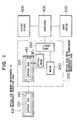
- FIG. 1 shows a conceptual diagram of an information processor of the present invention.
- the information processor of the present invention is composed of an optical disk-in-card 100 consisting of a transparent protective case 120 housing at least one recording layer of a rotatable disk type optical disk memory 140 of a recording layer, an optical disk drive, a processor 400, an input means 500 and an output means 600.
- the magneto-optical disk-in-card 100 incorporated in a transparent protective case is composed of a transparent protective case 120 housing a magneto-optical disk memory 140, a first magnetic field application means for initializing an auxiliary recording layer and a second magnetic field application means for recording information a recording layer, and is detachable from the disk drive 200.
- an optical disk memory such as a phase-change type, write-once type, and/or read-only type may also be used in place of the magneto-optical disk memory 140.
- the optical disk is incorporated in a transparent protective case is composed of an optical disk and a transparent protective case.
- the disk drive 200 is composed of an optical head 210 for write, read and overwrite, a motor 240 for rotating the optical disk 140 and a drive circuit 260 for controlling the optical head 210 and the motor 240.
- the optical head 210 is provided with an objective lens 219 for irradiating the optical disk 140 with light.
- the drive circuit 260 controls the rotation speed of the motor 240 and also fulfils functions of modulation of data for write/overwrite and demodulation of data for read in accordance with an instruction from the processor 400.
- the processor 400 performs arithmetic processing or write/read in and from the magneto-optical disk 140 in accordance with an instructions from the input means 500, and outputs the written information in the magneto-optical disk 140 or processing results through the output means 600.
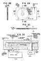
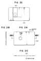
- Fig. 2A, Fig. 2B, Fig. 2C and Fig. 2D show an embodiment of the magneto-optical disk-in-card incorporated in a transparent protective case best suited for executing the present invention.
- the optical head 210 and the motor 240 for rotating the optical disk 140 are shown additionally in the detailed portion of the magneto-optical disk-in-card.
- a disk retainer 242 and a level 243 are provided so as to fix the optical disk 140.
- the magneto-optical disk 140 is incorporated in a protective case 120, 121 of a credit card size in the magneto-optical disk-in-card 100 of the present embodiment.
- a permanent magnet 180 for magnetic field application for initializing the auxiliary recording layer and a permanent magnet 181 for magnetic field application for writing in the recording layer are formed on the disk in the transparent protective case 121. It is better for the permanent magnet for magnetic field application for initialization and the permanent magnet for magnetic field application for recording to be fixed both at a length a little longer than the radial length of the recording area of the magneto-optical disk of the magneto-optical disk memory card because initialization and writing can be executed up to the innermost periphery or the outermost periphery of the disk.
- configurations of the permanent magnet for magnetic field application for initialization and the permanent magnet for magnetic field application for recording may be rectangular when the rotation speed of the disk is as low as 1,800 rpm.
- the manufacture of the permanent magnet for magnetic field application for initialization and the permanent magnet for magnetic field application for writing may be made by cutting out of a bulk material and adhering with adhesives, or by any of thin film forming methods such as a vacuum deposition method, a sputtering method and an ion beam sputtering method.
- At least a light beam incident portion 152 of the protective case is composed of a transparent plate in the magneto-optical disk 140.
- a window of the protective case was opened so that light is directly incident to an optical disk when light was incident. Therefore, dust and dirt entered through the window for light incidence, and it was required to use a transparent substrate having a thickness of 1.2 mm for the substrate as a countermeasure thereagainst.
- the substrate for supporting the optical disk medium needs not have the thickness of 1.2 mm.
- dust in air does not stick to a substrate 130 and a reading medium 145 consisting of an auxiliary recording layer and recording layer, thus producing an effect that the substrate having a thickness of 1.2 mm which has been heretofore deemed indispensable may be made thinner by forming the total of the plate thickness d2 of the transparent protective case 120 and the plate thickness d1 of the substrate 130 in approximately 1.2 mm.
- Fig. 3 shows another embodiment in place of Fig. 2D.
- the thickness d2 of the transparent protective plate is made at approximately 1.2 mm, it is not required to have light incident from the substrate 130 side, thus making it possible to use for the substrate 130 a metal, a metallic foil and an organic material having no light permeability such as an aluminum foil made thinner by cold processing and an alloy foil thereof, a stainless steel foil, and a titanium foil or an alloy foil thereof.
- the magneto-optical disk is fixed to the rotary shaft 241 and rotated, but is retained by the disk retainer 242 for stable rotation.
- the protective case 121 having no light incident portion it may be either transparent or opaque.
- the magneto-optical disk 140 is not fixedly attached to the protective case 120, 121, but is made rotatable freely.
- Fig. 4 shows an embodiment of an optical disk memory such as a phase-change type, write-once type, and/or read-only type contained in a transparent protective case (hereafter referred to as an "optical disk-in-card") best suited to realize an optical disk memory of the present invention, and the section of this figure is the same as Fig. 2C.
- the optical disk 140 incorporated in the protective case 120, 121 each in a card in a card size in the optical disk-in-card 100.
- at least the light beam incident portion 152 of the protective case is formed of a transparent protective plate in the optical disk 140.
- the window of the protective case was also opened like a magneto-optical disk unit so as to have light incident directly to the optical disk when light was incident. Therefore, since dust and dirt entered through the window for light incidence, it has been required to use a transparent substrate having a thickness of 1.2 mm for the substrate as a countermeasure.
- the thickness of the substrate for supporting the optical disk medium needs not be 1.2 mm.
- the optical disk 140 is not fixedly attached to the protective case 120, but is made rotatable freely.
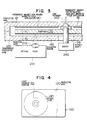
- Fig. 5A and Fig. 5B show an embodiment of an optical disk in the optical disk-in-card 100.
- the optical disk 140 is formed of a substrate 143 and a recording medium 145.
- a indicates a recording area and b indicates a non-recording area.
- the memory capacity for an optical disk-in-card is estimated.
- the outside dimension of a card has been already standardized, and the overall size is approximately 54 mm x 86 mm.
- the size of the protective case is also substantially in accordance with the size of the card in order to be used as a portable memory.
- the memory capacity is estimated here assuming that a protective case having the overall size of 54 mm x 86 mm is used. Since the breadth is 54 mm, it is preferable that the outside dimension of the optical disk is 50 mm and less when 1 mm is assigned to edges, respectively. Further, since it is preferable that the recording area a in the optical disk is located about 1 mm inside the overall size of the disk, the outside diameter of the recording area a is preferably at approximately 48 mm.
- the inside diameter of the recording area a is determined depending on the sizes of hub fitting for disk rotation and the disk retainer portion. Since about 15 to 28 mm is sufficient for the disk retainer portion, it may be concluded that 15 mm to 48 mm may be used as the recording area. When the outside dimension of the recording area is given, the memory capacity reaches the maximum when he inside diameter is selected at half of the outside dimension.
- the memory capacity when 24 mm to 48 mm is used as the recording area is estimated here.
- 1.6 ⁇ m is adopted as the spacing between tracks. Therefore, 7,500 tracks are obtained when the number of tracks are estimated with the above.
- the bit density is at approximately 1.4 ⁇ m/bit, the number of bits per track is obtained at approximately 53.8 Kbits per track.
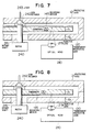
- Fig. 6 shows an embodiment of an magneto-optical disk in the magneto-optical disk-in-card 100.
- the magneto-optical disk 140 is composed of the recording medium 145 consisting of the substrate 130, the auxiliary recording layer and the recording layer.
- Fig. 6 is a partial sectional view showing another embodiment of the magneto-optical disk 140 shown in Fig. 5A.
- the substrate 130 needs to be transparent with respect to the wavelength of light employed.
- 145-1 becomes the write layer and 145-2 becomes the auxiliary recording layer.
- 145-1 becomes the auxiliary recording layer and 145-2 becomes the recording layer among recording medium when light is incident from the side of the recording medium 145 as shown in Fig. 3.
- the substrate 130 may be either transparent or opaque.
- the capacity, etc. of the memory for the magneto-optical disk-in-card is substantially similar to that of the memory for the optical disk-in-card.
- Fig. 7 and Fig. 8 are for explaining the concept of the present invention using an optical disk-in-card, and correspond to Fig. 2D and Fig. 3. With this, it becomes possible to make the optical disk thinner, and in its turn to make an information processor such as a lap top computer thinner.
- the present invention is composed of the substrate 130 supporting the recording medium 145, a protective case 120, 121 for protecting them, the motor 240 for rotating a disk and the optical head 210.
- the optical head may be realized essentially with an optical system as described in Nikkei Electronics, Nov. 21, 1983, pp. 189 - 213.
- Write/read/erase of the optical disk are implemented with such a composition as follows. That is, new information is recorded on old information by modulating the power of a semiconductor laser in the optical head 210 between an erasing power and a writing power at the time of write/erase.
- the reflectance of the optical disk is read by contracting the semiconductor laser power to a comparatively small power and radiating it continuously at the time of reading.
- a feature of the present invention exists in that a laser beam is radiated to the recording medium 145 through the transparent protective case 120.
- the substrate having a thickness of 1.2 mm which has been heretofore deemed indispensable may be made thinner by making the total of the plate thickness d2 of the transparent protective case 120 and the plate thickness d1 of the substrate 130 approximately 1.2 mm.
- the thickness d2 of the transparent protective plate of the present invention is made to be approximately 1.2 mm as shown in Fig. 8, it is not necessary to have light incident from the substrate 130 side, then a material having no light permeability can be used for the substrate 130. Further, the optical disk is fixed to the rotary shaft 241 and rotated, but is retained by the disk retainer 242 for stable rotation. Furthermore, since the protective case 121 is not a light incident portion, it may be either transparent or opaque.
- a recording medium best suited to realize the present invention.
- a read-only medium such as a compact disk, a write once optical recording medium utilizing hole boring and phase-change, and a reversible optical read medium utilizing magneto-optical effect and phase-change may be used. That is, any medium which is able to read or write/erase by means of a laser beam may be used as a medium in the present invention.
- Fig. 9 shows principles of write/erase/read of a phase-change optical disk.
- writing is realized by irradiating a recording medium with a laser beam of comparatively high power and quenching a recording film 142 after melting, thereby to bring the recording film 142 under amorphous state.
- erasing is realized by irradiating the recording film 142 with a laser beam of comparatively low power and bringing the recording film 142 in amorphous state under a crystallized state.
- reading is performed in such a manner that the recording medium is irradiated with continuous light of further lower power, thereby to read information by the difference between reflection factors under amorphous and crystallized states.
- phase-change medium such as an In-Sb-Te recording film described in Proc. Soc. Photo-Opt. Inst. Eng. (SPIE), Vol. 1078, pp. 11 - 26, (1989) or a recording film capable of overwrite described in Proc. Soc. Photo-Opt. Inst. Eng. (SPIE), Vol. 1078, pp. 27 - 34, (1989) may be used as the recording film 142.
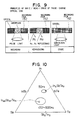
- Fig. 10 shows the crystallization time of an In-Sb-Te material, but this recording film 142 has different crystallization times depending on the composition of the material and has a crystallization time ranging from 50 ns to 500 ns.
- a recording film having a crystallization time in the range of approximately from 500/v ns to 1,500/v ns.
- Fig. 11 shows a film structure best suited to be used for the optical disk medium shown in Fig. 7.
- the optical disk medium is composed of a light permeable substrate 130, a first light interference film 141 having a high refractive index characteristic, a recording film 142, a second light interference film 143 having a high refractive index characteristic, a reflecting film 144 and a protective film 145a.
- light is incident from the substrate side.
- Fig. 12 shows a film structure best suited to be used as the optical disk medium shown in Fig. 8.
- the interference film fulfils the functions of improvement of contrast by light interference and a control film of heat conduction characteristic.
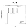
- Fig. 13 shows a modulation method of the laser power at the time of overwriting. That is, the laser power is modulated between the power level for erasing and the power level for recording at the time of overwriting. At this time, the laser power for erasing is selected from the power which is able to crystallize the recording film when this power is continued to be radiated, and the power for recording is selected from the power which is able to bring the recording film under amorphous state.
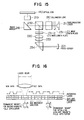
- Fig. 14A and Fig. 14B show an example of the optical head 210 best suited to execute the present invention.
- an actuator for driving an objective lens was provided for focal point control, but it was difficult to make the optical head thinner because of this actuator.
- the actuator for the objective lens 219 is deleted, and a relay lens 216 is provided instead and moved in a parallel direction with the disk, thereby to realize focal point control.
- aberration on a disk is compensated in an ordinary objective lens by utilizing a plurality of lenses, but a part thereof is split and moved to the whole surface of a riser mirror 218 so as to make the optical head thinner.
- the optical head 210 shown in Fig. 14A will be described.
- Luminous flux emitted from a semiconductor laser 211 passes through a collimator lens 212 and a shaping prism 213, and the luminous flux is reflected by a polarizing prism 214.
- the reflected luminous flux passes through a condenser lens 220 for detection, and is detected by an optical sensor 221.
- the luminous flux which has passed through the polarizing prism 214 passes through a ⁇ /4 plate 215 and is converged appropriately by a relay lens 216 having a focus actuator 230, and then passes through an objective lens 217 and is reflected by a riser mirror 218, and is radiated onto the optical disk thereafter through an objective lens 219.
- the optical head 210 shown in Fig. 14B includes the optical sensor 221 provided with light permeability in place of the polarizing prism 214 and a relay lens 216 provided with no focus actuator 230.
- the optical head 210 may be realized with the optical system shown in Fig. 15.
- a divergent luminous flux emitted from a semiconductor laser 211 passes through a beam splitter (hereafter abbreviated as BS) 232 through a ⁇ /2 plate 231-1 and a collimator lens 212 and becomes parallel luminous fluxes.
- the parallel luminous fluxes are reflected further by the riser mirror 218, and converted thereafter into parallel fluxes again by the objective lens 219 and radiated onto the optical disk 140.
- BS beam splitter
- the luminous flux passes through a ⁇ /2 plate 231-2 after reflected by the BS 232, and is incident to a detection lens 220 consisting of a combination of a convex lens and a concave lens so as to become a convergent luminous flux.
- the convergent luminous flux is incident to a cylindrical lens 233, thus producing astigmatism.
- the luminous flux which has passed the cylindrical lens 233 is incident to a micro BPS 234 which is an analyzer.
- This micro BPS 234 is composed of a parallelogram prism and transparent parallel flat plates putting a polarizing film which transmits P-polarized light (polarized light in a vibration direction parallel with the paper surface) and reflects S-polarized light (polarized light in a vibration direction perpendicular to the paper surface) therebetween.
- the convergent luminous flux is incident to the polarizing film from the upper side of the parallelogram prism.
- the P-polarized light which has transmitted through the polarizing film is totally reflected by the back plane of the parallel flat plates and passes through the polarizing film again, and then advances toward the left side of the parallelogram prism.
- the S-polarized light reflected by the polarizing film also advances in the same direction as the P-polarized light, and is incident to the optical sensor 221 at a certain interval. This interval is controlled by means of the parallel flat plates.
- Fig. 16 shows the principle of overwriting a magneto-optical disk by laser power modulation.
- the optical recording medium has a two-layer structure of the recording layer and the auxiliary recording layer, in which the recording layer on the side applied with a laser beam is composed of TbFe which has a large coercive force Hc and a low curie temperature and the auxiliary recording layer is composed of GdTbFe which has a small coercive force Hc and a high curie temperature.
- the permanent magnet for applying initializing auxiliary magnetic field is made to generate a magnetic field stronger than that of the permanent magnet for applying recording magnetic field.
- magnetization of the auxiliary recording layer having small Hc is oriented in a magnetizing direction in the permanent magnet for applying initializing auxiliary magnetic field.
- the magnetizing direction is not reversed.
- the recording medium reaches a position where the laser beam is applied under abovementioned state, magnetization of the auxiliary recording layer having a high curie temperature is preserved as is and only the recording layer reaches the curie temperature and higher when the laser power is weak.
- the magnetization of the recording layer is oriented in the magnetizing direction of the auxiliary recording layer in the cooling process.
- the magnetization thereof is oriented in the direction of the magnetic field of the permanent magnet for applying recording magnetic field along with the recording layer. That is, since the magnetizing direction is determined by the difference in the intensity of the laser power, viz., modulation of the laser power, a process of erasing old written contents becomes unnecessary, thus making overwriting possible. Due to such a principle, it is required that the permanent magnet for applying recording magnetic field is positioned where the laser beam is applied. However, the permanent magnet for applying initializing auxiliary magnetic field needs not be placed at positions shown in Fig. 2D and Fig. 3, but may be placed at any position in the case on the recording area of the magneto-optical disk which does not overlap with the permanent magnet for applying recording magnetic field.
- the optical recording medium is not limited to a Tb21Fe79 recording layer and a Gd24Tb3Fe73 auxiliary recording layer so far as a two-layer structure of a recording layer having a large coercive force Hc and a low curie temperature and an auxiliary recording layer having a small coercive force Hc and a high curie temperature is formed.
- a composition of a GdTbFeCo recording layer, a GdFeCo intermediate layer and a TbFeCo auxiliary recording layer which is a two-layer lamination having a third magnetic layer intermediately as a means for reducing magnetic wall energy at the interface may be used as well.
- the permanent magnet such as SmCo and NdFeB used as a second magnetic field application means for recording in the recording layer is not transparent with respect to the wavelength of incident light as seen from the principle of overwriting, it is required that the means for applying magnetic field for recording in the recording layer is self-contained in a case on the opposite side of the light incident portion and the disk.
- the first magnetic field application means for initializing the auxiliary recording layer is shown to be self-contained in the case on the opposite side of the light incident portion and the disk, but the first magnetic field application means for initializing the auxiliary recording layer may be self-contained in the case on the light incident side.
- Fig. 17 shows a film structure best suited to be used as a magneto-optical disk medium shown in Fig. 2D.
- the magneto-optical disk medium is composed of a light permeable substrate 130, a first light interference film 141 having a high refractive index characteristic, recording layer 145-1, an auxiliary recording layer 145-2, a second light interference film 143 having a high refractive index characteristic, a reflecting film 144 and a protective film 145a.
- light is incident from the substrate side.
- Si2N4, AlN, Ta2O5, ZnS and the like can be used as a dielectric film having a high refractive index. An example of a manufacturing method and performance will be shown.
- a first light interference film Si3N4 having a thickness of 100 nm, then a recording film Tb20Fe80 having a thickness of 100 nm, an auxiliary recording film Gd24Tb5Fe71 having a thickness of 50 nm, a second light interference film Si3N4 having a thickness of 100 nm and an Au reflecting film having a thickness of 100 nm have been formed by applying a sputtering method to a glass substrate having a thickness of 0.5 mm and a diameter of 48 mm on which a groove having a depth of 100 nm and a pitch of 1.6 ⁇ m is formed in a spiral form.
- FIG. 2D a polycarbonate substrate having a thickness of 0.6 mm obtained by cutting a SmCo magnet having Hc at 40,000 e as the first magnetic field application means for initializing the auxiliary recording layer and a SmCo magnet 5 mm wide and 25 mm long having Hc at 3,000 e as the second magnetic field application means for recording in the recording layer out of a bulk.
- the performance of such a magneto-optical disk-in-card has been evaluated.
- the disk-in-card was rotated at the rotation speed of 3,600 rpm and tested by the laser modulation method at the time of overwriting shown in Fig. 13. That is, when 6.6 mW was set on the write film surface as the bias power and 8.9 mW was set on the recording film surface as the recording power and overwrite test was executed while modulating the optical beam between 2 MHz and 3 MHz, C/N was obtained at 54 dB and the error generation factor was obtained at less than 10 ⁇ 5.
- Fig. 18 shows a film structure best suited to be used as the magneto-optical disk medium shown in Fig. 3.
- the interference film fulfils the functions of improvement of contrast by means of interference of light and the control film of heat conduction characteristic.
- the light incident side is not on the substrate side, it is possible to form the same film composition as that shown in Fig. 18 on the opposite side of the substrate, thereby to use both sides of one sheet of substrate. An example of a manufacturing method and performance is shown.
- an Au reflecting film having a thickness of 100 nm, a second light interference film AlN having a thickness of 100 nm, an auxiliary recording layer Tb24Fe65Co11 having a thickness of 100 nm, a recording film Gd24Tb3Fe73 having a thickness of 50 nm and a first light interference film Si3N4 having a thickness of 100 nm have been formed by applying a sputtering method to a stainless steel substrate having 0.5 mm in thickness and 48 mm in diameter on which a groove having 100 nm in depth and 1.6 ⁇ m in pitch is formed in a spiral form. Furthermore, ultraviolet hardening resin having a thickness of 100 ⁇ m has been formed as a protective film thereon.
- This magneto-optical disk was attached to the transparent case shown in Fig. 3, that is, a polycarbonate substrate having a thickness of 0.6 mm obtained by cutting a SmCo magnet having Hc at 40,000 e as the first magnetic field application means for initializing the auxiliary recording layer and a SmCo magnet 5 mm wide and 25 mm long having Hc at 3,000 e as the second magnetic field application means for recording in the recording layer out of a bulk. The performance of such a magneto-optical disk-in-card has been evaluated.
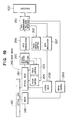
- the optical disk drive circuit system 260 is explained in detail in Fig. 19.
- the optical disk drive circuit system 260 is composed of a data management portion 261, a track address control portion 262, a track control portion 263, a focus control portion 264, a photo detector and amplifier 265, a data demodulation portion 266, a data modulation portion 267, a laser drive 268 and a motor control portion 269.
- a track address to be written is determined in the track address control portion 262, and the data modulation portion 267 converts the data given from a processor 400 into "0" and "1" pattern to be recorded on the optical disk by a modulation system.
- the modulation system includes 2 7 modulation and 4-15 modulation, which, however, are used properly depending on the system.
- the laser drive 268 the laser power is modulated between the bias power and the writing power as shown in Fig. 13 in accordance with the "0" and "1" pattern determined by the data modulation portion 267. Further, at the time of reading data, a track address designated by the processor 400 is selected, the laser power is set at a constant value of approximately 1 to 2 mW, the reflectance of the optical disk or the karr rotation of the magneto-optical disk 140 is read by the photo detector and amplifier 265, and the data are demodulated by the data demodulation portion 266.
- the result of the photo detector and amplifier 265 may be utilized as the signal of the track control portion 263 and the focus control portion 264, but the functions of these portions can be realized with the functions which have been heretofore employed in a compact disk and an optical disk device.
- the motor control portion 269 controls the number of rotation of a motor 240 for rotating the optical disk 140.
- CAV Constant Angular Velocity
- CLV Constant Linear Velocity
- an optical or magneto-optical disk-in-card of the present invention a means for rotating the disk is self-contained in the card. With this, it is possible to make the thickness of the whole information processor thinner by the portion of the motor.
- Fig. 20 shows another embodiment of the disk-in-card 100.
- the basic composition is the same as the composition shown in Fig. 4, and the light incident portion is covered with a transparent protective case, but the feature of the embodiment shown in Fig. 20 exists in that a protective cover 160 is provided.
- the card case 120 Since the disk-in-card 100 of the present invention is carried freely, the card case 120 is flawed sometimes. There is no problem even if other parts than the light incident portion are flawed, but the card case needs to be replaced sometimes if the light incident portion is flawed. It is an object of the present invention to reduce the frequency of replacement of the card case. That is, by providing the protective cover 160 on the card case 120, it is prevented that the light incident portion is flawed, and incidence of light is made free by opening the protective cover 160 when the optical disk-in-card is inserted into the optical disk drive 200.
- Fig. 21A, Fig. 21B and Fig. 21C show still another embodiment of the optical disk-in-card 100.
- Transparent protective plates 120 and 121 each have a film thickness of approximately 0.5 to 1.2 mm and the optical disk 140 (not shown) is inserted between these protective plates 120 and 121.
- 170 indicates a magnet clamp for fixing the optical disk 140 to the rotary shaft for rotating the optical disk.
- Fig. 22A is a sectional view taken along arrow marks XXIC-XXIC shown in Fig. 21A
- Fig. 22B and Fig. 22C are enlarged views shown with arrow marks F and G shown in Fig. 22A.
- the optical disk 140 is fixed with the magnet clamp 170 and is apart from the protective plates 120 and 121.
- Fig. 23A and Fig. 23B show an example of the optical disk in this disk-in-card 100.
- the central part of the disk is hollow in the example shown in Fig. 5B, whereas the example shown in Fig. 23B has a feature that the disk is fixed with the magnet clamp 170 at the central part thereof.
- Fig. 24 is an enlarged view shown with an arrow mark J in Fig. 23B and shows a preventive method against mixing of dust and dirt into the recording area.
- the light incident portion is covered with a transparent protective cover.
- dust and dirt will never get directly into the recording area, but the central part of the disk is open for the purpose of rotation, thus it is possible that dust and dirt mix in through this central part.
- a dust protective mat 125 is laid in a non-recording area so as to prevent mixing of dust and dirt from the central part of the disk.
- a magnet clamp is utilized was explained with reference to Fig. 24, however, it is a matter of course that this dust protective mat is applicable to the example shown in Fig. 2.
- Fig. 25 shows another example of a counter-measure against dust corresponding to Fig. 24.
- Fig. 24 there was a fear that dust and dirt mix in because the central part of the disk was open.
- the present embodiment has a feature that a bearing 126 is provided at the central part of the disk so as to delete the opened part.
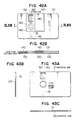
- Fig. 26A, Fig. 26B, Fig. 26C and Fig. 26D show another embodiment related to the card configuration.
- a case that the card configuration has an equivalent configuration to a credit card has been described, but any configuration may be applied so far as the size thereof may contain the optical disk.
- Fig. 26A shows an embodiment of a substantially square card having a protective cover 160.
- the size of the optical disk has been shown at approximately 50 mm in the present invention, but the size may be altered at need. That is, the present invention is applicable to any size such as 12 inches, 8 inches, 5.25 inches, 5 inches and 3.5 inches which have been heretofore developed.
- Fig. 27 shows another embodiment of the magneto-optical disk-in-card 100 for realizing the present invention.
- the basic composition is the same as the composition shown in Fig. 2A and the light incident portion is covered with a transparent protective case, but the feature of the embodiment shown in Fig. 27 exists in that a protective cover 160 is further provided.
- the permanent magnet for initializing the auxiliary recording layer of the recording medium and the permanent magnet for recording in the recording layer are in the protective case. Since the magneto-optical disk-in-card 100 of the present invention is carried freely, the card 120 is flawed sometimes. There is no problem even if other parts that the light incident portion are flawed, but the card case needs to be replaced sometimes if the light incident portion is flawed.
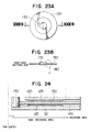
- Fig. 28A, Fig. 28B and Fig. 28C show another embodiment of the magneto-optical disk-in-card 100.
- Fig. 28A shows the external appearance of a magneto-optical disk of a card size attached with the transparent protective case 120 and the protective case 121.
- the permanent magnet 181 for initializing magnetic field and a permanent magnet 180 for recording magnetic field are fitted to the protective case 121.
- the transparent protective cases 120 and 121 have a film thickness of approximately 0.5 to 1.2 mm, respectively, and the magneto-optical disk 140 (not shown) is inserted between these protective cases 120 and 121.
- 170 indicates the magnet clamp which fixed the magneto-optical disk 140 to a rotary shaft for rotation.
- FIG. 29A shows a sectional structure of the magneto-optical disk in Fig. 28A shown along arrow marks XXVIIIC-XXVIIIC.
- the magneto optical disk 140 is fixed by the magnet clamp 170 and is apart from the protective case 120, 121.
- Fig. 29B and Fig. 29C are enlarged views showing the parts shown with arrow marks K and L in Fig. 29A in more details.
- Fig. 30 shows another embodiment corresponding to Fig. 29C, which shows an example of a magneto-optical disk in the magneto-optical disk-in-card 100.
- the central part of the disk is hollow in the example shown in Fig. 5B, whereas the example shown in Fig. 30 has a feature that the disk is fixed with the magnet clamp 170 at the central part thereof.
- Fig. 30 shows a preventive method against mixing of dust and dirt into the recording.
- the light incident portion is covered with a transparent protective cover. Therefore, dust and dirt will never get directly into the recording area, but the central part of the disk is open for the purpose of rotation, thus it is possible that dust and dirt mix in through this central part.
- a dust protective mat 125 is laid in a non-recording area so as to prevent mixing of dust and dirt from the central part of the disk.
- Fig. 31 shows another example of a counter-measure against dust.
- Fig. 30 there was a fear that dust and dirt mix in because the central part of the disk was open.
- the present embodiment has a feature that a bearing 126 is provided at the central part of the disk so as to delete the opened part.
- Fig. 32A, Fig. 32B, Fig. 32C and Fig. 32D show another embodiment related to the card configuration.
- a case that the card configuration has an equivalent configuration to a credit card has been described, but any configuration may be applied so far as the size thereof may contain the magneto-optical disk.
- Fig. 32A shows an embodiment of a substantially square card.
- the size of the optical disk has been shown at approximately 50 mm in the present invention, but the size may be altered. That is, the present invention is applicable to any size such as 12 inches, 8 inches, 5.25 inches, 5 inches and 3.5 inches which have been heretofore developed.
- Fig. 33 shows an embodiment in case the present invention is applied to a lap top computer.
- This embodiment is composed of a lap top computer 400 including a processor unit 401 and a semiconductor main memory 402, and a keyboard 410 and a display 420 are connected thereto through a system bus 403, but the feature of the present invention exists in that an optical or magneto-optical disk-in-card drive 200 is connected through an optical or magneto-optical disk-in-card interface 404.
- the optical or magneto-optical disk-in-card 100 of the present invention has a capacity wave than 10 MB in spite of the small size having the overall size of approximately 50 mm. With this, large-scale arithmetic processing of a minicomputer is made possible though it is a lap top computer. Further, it is detachable from the optical or magneto-optical disk-in-card drive 200, thus providing a system convenient for transportation.
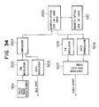
- Fig. 34 shows an embodiment when the present invention is applied to a camera.
- Signal processing of an electronic camera utilizing a floppy disk can be utilized for basic signal processing thereof.
- Signal processing of an electronic camera consists of an FM modulation element of a picture image, a modulation element of data such as data, a recording portion into a floppy disk and a video signal read portion as described in the Nikkei Electronics, Dec. 12, 1988, pp. 195 - 201.
- the feature of the present invention exists in that the optical or magneto-optical disk-in-card 100 is utilized as the recording medium of a signal.
- the optical or magneto-optical disk-in-card 100 of the present invention not only has a large capacity, but also is easy for handling and highly reliable because the optical disk is self-contained in a transparent protective case.
- an electric signal converted photoelectrically by a solid state image pickup element 501 of a CCD or a MOS is FM-modulated.
- the data are converted by a differential phase shift keying (DPSK) system and the like, synthesized with FM modulation (block 504) and recorded in the optical or magneto-optical disk-in-card 100 through the optical or magneto-optical disk-in-card drive 200.
- DPSK differential phase shift keying
- the picture image is demodulated by an FM demodulator 505 and the data are demodulated by a data demodulator 506, and both are converted into video signals such as NTSC by means of a converter 507 into video signals.
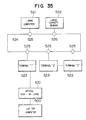
- Fig. 35 shows an example in which the optical or magneto-optical disk-in-card 100 is utilized as an interface between a lap top computer 500 and a terminal 523 of a large computer 521.
- the large computer 521 has a memory 522 of a large capacity such as an ordinary magnetic disk, and is connected with a plurality of terminals 523 through a network 524 and stations 525 for utilization.
- a network 524 and stations 525 for utilization.
- an optical or magneto-optical disk-in-card 100 of the present invention is used in a lap top computer 500 and the optical or magneto-optical disk-in-card 100 of the present invention is also used as a memory of the terminal 523 of the large computer.
- the optical or magneto-optical disk-in-card 100 in common as the memory of the lap top computer 500 and the terminal 523 of the large computer in a manner as described above, it is possible to proceed with a work of creating a program and debugging at home or in an electric car where the terminal is not available.
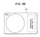
- Fig. 36 shows an application example of the optical or magneto-optical disk-in-card 100 when security is demanded of the memory.
- the optical or magneto-optical disk 140 has a feature of a large capacity, it is possible to check what type of pattern has been written with a microscope having a high enlargement ratio. It is not only possible to ensure security by utilizing a random number code and the like, but also to ensure higher security by providing a semiconductor memory on the card. In this case, it can be achieved by providing a semiconductor memory area "A" as shown in Fig. 36.
- this optical or magneto-optical disk memory card 100 can realize cash cards and information requiring secrecy such as a portable personal medical medium data base. In this case, it can be materialized with the hardware composition shown in Fig. 1.
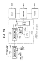
- Fig. 37 shows a conceptual diagram of an optical or magneto-optical disk-in-card memory of the present invention.
- the optical or magneto-optical disk memory of the present invention is composed of an optical or magneto-optical disk 100 in 50 mm ⁇ incorporated in a protective case of a card size, a disk drive 200 for the optical or magneto-optical disk-in-card, a processor 400, and input means 500 and an output means 600.
- the optical or magneto-optical disk-in-card 100 is composed of an optical disk 140, a light incident window 150, a card case 120 and a window cover 160, and is detachable from a disk drive 200.
- the disk drive 200 is composed of a write/read/erase optical head 210, a motor 240 for rotating the optical disk 140 and a drive circuit 260 for controlling the optical head 210 and the motor 240, and the light incident cover 150 is opened automatically so that light may be incident when the optical or magneto-optical disk-in-card 100 is set.
- the drive circuit 260 controls the number of rotation of the motor 240 and also fulfils the functions of modulation and demodulation for reading of write/erase data by the command from the processor 400.
- the processor 400 executes arithmetic processing or write/read to the optical disk in accordance with the command from the input means 500, and also outputs the contents of the memory of the optical disk 140 or operation results through the output means 600 as occasion demands.
- Fig. 38 shows an embodiment of optical disk-in-card 100 best suited for realizing the present invention.
- the optical disk medium 140 is incorporated in a protective case 120, 121 of a card size in the present optical disk-in-card 100.
- a window 150 is provided for another incidence of light, and the optical disk is usually covered with a cover 160.
- the window cover 160 of the protective case is opened and light is made incident directly to the substrate of the optical disk, and a magnetic field generating means is used while allowing it to come near to the optical disk in the case of a magneto-optical disk.
- Fig. 39A and Fig. 39B show an external appearance of the optical disk-in-card 100 when the window cover 160 is opened. When the window cover 160 is opened, the optical disk 140 is exposed, and the optical head is able to make access directly to the optical disk.
- Fig. 40A, Fig. 40B and Fig. 40C show an embodiment in which the optical disk memory is rotated by means of a magnet clamp. For further details, this embodiment is similar to that shown in Fig. 21A.
- Fig. 41 shows an embodiment of the magneto-optical disk-in-card 100 best suited realizing the present invention.
- the optical disk medium 140 is incorporated in the protective case 120, 121 of a card size.
- a window 150 is provided in the protective case for another incidence of light, and the optical disk is usually covered with a window cover 160.
- the window cover 160 of the protective case is opened and light is made incident directly to the substrate of the optical disk, and a magnetic field generating means is used while allowing it to come near to the optical disk in the case of a magneto-optical disk.
- Fig. 42A and Fig. 42B show an external appearance of the optical disk-in-card 100 when the window cover 160 is opened. When the window cover 160 is opened, the optical disk 140 is exposed, and the optical head is able to make access directly to the optical disk.
- Fig. 43A, Fig. 43B and Fig. 43C show an embodiment in which the optical disk memory of Fig. 23 is rotated by means of a magnet clamp. For further details, this embodiment is similar to that shown in Fig. 28A.
Applications Claiming Priority (4)
| Application Number | Priority Date | Filing Date | Title |
|---|---|---|---|
| JP249154/89 | 1989-09-27 | ||
| JP24915489A JPH03113832A (ja) | 1989-09-27 | 1989-09-27 | 情報処理装置及びそれに用いる光ディスクメモリ |
| JP315289/89 | 1989-12-06 | ||
| JP31528989A JPH03254446A (ja) | 1989-12-06 | 1989-12-06 | 情報処理装置及びそれに用いる光磁気デイスクインカード |
Publications (3)
| Publication Number | Publication Date |
|---|---|
| EP0420112A2 true EP0420112A2 (de) | 1991-04-03 |
| EP0420112A3 EP0420112A3 (en) | 1992-08-26 |
| EP0420112B1 EP0420112B1 (de) | 1998-12-23 |
Family
ID=26539118
Family Applications (1)
| Application Number | Title | Priority Date | Filing Date |
|---|---|---|---|
| EP90118321A Expired - Lifetime EP0420112B1 (de) | 1989-09-27 | 1990-09-24 | Magnetooptische Diskette |
Country Status (6)
| Country | Link |
|---|---|
| EP (1) | EP0420112B1 (de) |
| KR (1) | KR910006931A (de) |
| CN (1) | CN1050634A (de) |
| AU (1) | AU624532B2 (de) |
| CA (1) | CA2025724C (de) |
| DE (1) | DE69032850T2 (de) |
Cited By (5)
| Publication number | Priority date | Publication date | Assignee | Title |
|---|---|---|---|---|
| EP0510889A1 (de) * | 1991-04-19 | 1992-10-28 | Sharp Kabushiki Kaisha | Kassette für flexible optische Scheibe |
| FR2682519A1 (fr) * | 1991-10-10 | 1993-04-16 | Bertaux Christophe | Carte musicale a lecture optique a changement de disque. |
| EP0474505A3 (en) * | 1990-09-07 | 1993-05-26 | Nikon Corporation | Magnetooptic recording medium cartridge |
| EP0833317A3 (de) * | 1996-08-27 | 1998-06-24 | Matsushita Electric Industrial Co., Ltd. | Magnetooptisches Aufzeichnungsmedium und zugehöriges Leseverfahren |
| WO2004017322A1 (en) * | 2002-08-14 | 2004-02-26 | Koninklijke Philips Electronics N.V. | Disc cartridge |
Families Citing this family (1)
| Publication number | Priority date | Publication date | Assignee | Title |
|---|---|---|---|---|
| KR20020084781A (ko) * | 2001-05-03 | 2002-11-11 | 지성규 | 체내 흡수가 용이한 단백화 양이온의 제조방법 및 동방법에 의해 제조된 단백화 양이온을 유효성분으로 하는건강식품 |
Family Cites Families (9)
| Publication number | Priority date | Publication date | Assignee | Title |
|---|---|---|---|---|
| US4603414A (en) * | 1983-02-14 | 1986-07-29 | News Log International | Apparatus for making a data record carrier |
| US4592042A (en) * | 1983-02-16 | 1986-05-27 | Lemelson Jerome H | Record card transducing apparatus and method |
| NL8301632A (nl) * | 1983-05-09 | 1984-12-03 | Philips Nv | Registratiedrager waarin langs optische weg informatie kan worden ingeschreven en uitgelezen. |
| US4613966A (en) * | 1983-06-30 | 1986-09-23 | International Business Machines Corporation | Sealed encapsulation for floppy disk using centrifugal force to flatten disk |
| AU595206B2 (en) * | 1985-08-16 | 1990-03-29 | Laser Magnetic Storage International Company | Apparatus for providing access to a disk |
| JPS63266680A (ja) * | 1986-12-15 | 1988-11-02 | Hitachi Maxell Ltd | 光記録媒体 |
| JPS63291237A (ja) * | 1987-05-21 | 1988-11-29 | Mitsubishi Electric Corp | 光磁気記録再生用情報担体装置 |
| NL8800733A (nl) * | 1988-03-23 | 1989-10-16 | Jan Essebaggers | Informatiedrager voor compact reader. |
| JP2781625B2 (ja) * | 1989-12-13 | 1998-07-30 | 株式会社日立製作所 | 情報処理装置 |
-
1990
- 1990-09-19 AU AU63015/90A patent/AU624532B2/en not_active Ceased
- 1990-09-19 CA CA002025724A patent/CA2025724C/en not_active Expired - Fee Related
- 1990-09-24 DE DE69032850T patent/DE69032850T2/de not_active Expired - Fee Related
- 1990-09-24 EP EP90118321A patent/EP0420112B1/de not_active Expired - Lifetime
- 1990-09-25 KR KR1019900015156A patent/KR910006931A/ko not_active Ceased
- 1990-09-27 CN CN90108048A patent/CN1050634A/zh active Pending
Cited By (6)
| Publication number | Priority date | Publication date | Assignee | Title |
|---|---|---|---|---|
| EP0474505A3 (en) * | 1990-09-07 | 1993-05-26 | Nikon Corporation | Magnetooptic recording medium cartridge |
| EP0510889A1 (de) * | 1991-04-19 | 1992-10-28 | Sharp Kabushiki Kaisha | Kassette für flexible optische Scheibe |
| FR2682519A1 (fr) * | 1991-10-10 | 1993-04-16 | Bertaux Christophe | Carte musicale a lecture optique a changement de disque. |
| EP0833317A3 (de) * | 1996-08-27 | 1998-06-24 | Matsushita Electric Industrial Co., Ltd. | Magnetooptisches Aufzeichnungsmedium und zugehöriges Leseverfahren |
| US6018511A (en) * | 1996-08-27 | 2000-01-25 | Matsushita Electric Industrial Co., Ltd. | Magneto-optical recording medium and readout method of the same |
| WO2004017322A1 (en) * | 2002-08-14 | 2004-02-26 | Koninklijke Philips Electronics N.V. | Disc cartridge |
Also Published As
| Publication number | Publication date |
|---|---|
| KR910006931A (ko) | 1991-04-30 |
| DE69032850T2 (de) | 1999-05-12 |
| AU624532B2 (en) | 1992-06-11 |
| CN1050634A (zh) | 1991-04-10 |
| CA2025724A1 (en) | 1991-03-28 |
| EP0420112B1 (de) | 1998-12-23 |
| CA2025724C (en) | 1996-05-07 |
| EP0420112A3 (en) | 1992-08-26 |
| DE69032850D1 (de) | 1999-02-04 |
| AU6301590A (en) | 1991-04-11 |
Similar Documents
| Publication | Publication Date | Title |
|---|---|---|
| US4807204A (en) | Magneto-optical recording medium having pairs of mutually corresponding recording segments, and apparatus for recording information on the medium | |
| US5475656A (en) | Optical disk memory and information processing apparatus | |
| JP2804130B2 (ja) | 情報処理装置 | |
| JPS63291237A (ja) | 光磁気記録再生用情報担体装置 | |
| US5274612A (en) | Information processor and disk memory used in the same | |
| JPH05159387A (ja) | 光磁気ディスク | |
| EP0420112B1 (de) | Magnetooptische Diskette | |
| JPH03222133A (ja) | 光磁気記録媒体及び光磁気記録・消去方法 | |
| JPS6314347A (ja) | 光磁気記録装置 | |
| EP1511028A1 (de) | Optisches aufzeichnungsmedium und optische speichereinrichtung | |
| EP0510758A2 (de) | Verfahren zum thermomagnetischen Aufzeichnen und optischen Auslesen von Information | |
| JPH08339658A (ja) | 光ディスクカートリッジおよびそのドライブ装置 | |
| JPH0739061Y2 (ja) | 光磁気ディスク | |
| JP3162350B2 (ja) | 磁気ディスク | |
| JP2746313B2 (ja) | 情報記録方法 | |
| JPH03254446A (ja) | 情報処理装置及びそれに用いる光磁気デイスクインカード | |
| JP2749877B2 (ja) | 情報記録装置 | |
| JPH04245081A (ja) | 光ディスクメモリユニットおよび情報処理装置 | |
| JP2815122B2 (ja) | 情報記録装置 | |
| JPS6342053A (ja) | 情報記録媒体 | |
| JPH103706A (ja) | 光磁気ディスク及びその記録再生装置 | |
| JPS63239638A (ja) | 光磁気記録装置 | |
| JPH03178062A (ja) | 光ディスク | |
| JPH03113832A (ja) | 情報処理装置及びそれに用いる光ディスクメモリ | |
| JPH0969240A (ja) | 三次元記録媒体とその記録再生装置 |
Legal Events
| Date | Code | Title | Description |
|---|---|---|---|
| PUAI | Public reference made under article 153(3) epc to a published international application that has entered the european phase |
Free format text: ORIGINAL CODE: 0009012 |
|
| 17P | Request for examination filed |
Effective date: 19901206 |
|
| AK | Designated contracting states |
Kind code of ref document: A2 Designated state(s): DE FR GB IT NL |
|
| PUAL | Search report despatched |
Free format text: ORIGINAL CODE: 0009013 |
|
| AK | Designated contracting states |
Kind code of ref document: A3 Designated state(s): DE FR GB IT NL |
|
| 17Q | First examination report despatched |
Effective date: 19941103 |
|
| GRAG | Despatch of communication of intention to grant |
Free format text: ORIGINAL CODE: EPIDOS AGRA |
|
| GRAG | Despatch of communication of intention to grant |
Free format text: ORIGINAL CODE: EPIDOS AGRA |
|
| GRAG | Despatch of communication of intention to grant |
Free format text: ORIGINAL CODE: EPIDOS AGRA |
|
| GRAH | Despatch of communication of intention to grant a patent |
Free format text: ORIGINAL CODE: EPIDOS IGRA |
|
| GRAH | Despatch of communication of intention to grant a patent |
Free format text: ORIGINAL CODE: EPIDOS IGRA |
|
| GRAA | (expected) grant |
Free format text: ORIGINAL CODE: 0009210 |
|
| AK | Designated contracting states |
Kind code of ref document: B1 Designated state(s): DE FR GB IT NL |
|
| REF | Corresponds to: |
Ref document number: 69032850 Country of ref document: DE Date of ref document: 19990204 |
|
| ET | Fr: translation filed | ||
| ITF | It: translation for a ep patent filed | ||
| PGFP | Annual fee paid to national office [announced via postgrant information from national office to epo] |
Ref country code: FR Payment date: 19990716 Year of fee payment: 10 |
|
| PGFP | Annual fee paid to national office [announced via postgrant information from national office to epo] |
Ref country code: GB Payment date: 19990914 Year of fee payment: 10 |
|
| PGFP | Annual fee paid to national office [announced via postgrant information from national office to epo] |
Ref country code: NL Payment date: 19990930 Year of fee payment: 10 |
|
| PLBE | No opposition filed within time limit |
Free format text: ORIGINAL CODE: 0009261 |
|
| STAA | Information on the status of an ep patent application or granted ep patent |
Free format text: STATUS: NO OPPOSITION FILED WITHIN TIME LIMIT |
|
| PGFP | Annual fee paid to national office [announced via postgrant information from national office to epo] |
Ref country code: DE Payment date: 19991129 Year of fee payment: 10 |
|
| 26N | No opposition filed | ||
| PG25 | Lapsed in a contracting state [announced via postgrant information from national office to epo] |
Ref country code: GB Free format text: LAPSE BECAUSE OF NON-PAYMENT OF DUE FEES Effective date: 20000924 |
|
| PG25 | Lapsed in a contracting state [announced via postgrant information from national office to epo] |
Ref country code: NL Free format text: LAPSE BECAUSE OF NON-PAYMENT OF DUE FEES Effective date: 20010401 |
|
| GBPC | Gb: european patent ceased through non-payment of renewal fee |
Effective date: 20000924 |
|
| PG25 | Lapsed in a contracting state [announced via postgrant information from national office to epo] |
Ref country code: FR Free format text: LAPSE BECAUSE OF NON-PAYMENT OF DUE FEES Effective date: 20010531 |
|
| NLV4 | Nl: lapsed or anulled due to non-payment of the annual fee |
Effective date: 20010401 |
|
| PG25 | Lapsed in a contracting state [announced via postgrant information from national office to epo] |
Ref country code: DE Free format text: LAPSE BECAUSE OF NON-PAYMENT OF DUE FEES Effective date: 20010601 |
|
| REG | Reference to a national code |
Ref country code: FR Ref legal event code: ST |
|
| PG25 | Lapsed in a contracting state [announced via postgrant information from national office to epo] |
Ref country code: IT Free format text: LAPSE BECAUSE OF NON-PAYMENT OF DUE FEES;WARNING: LAPSES OF ITALIAN PATENTS WITH EFFECTIVE DATE BEFORE 2007 MAY HAVE OCCURRED AT ANY TIME BEFORE 2007. THE CORRECT EFFECTIVE DATE MAY BE DIFFERENT FROM THE ONE RECORDED. Effective date: 20050924 |