EP0420124A2 - Optische Einheit verwendbar für Laserdrucker oder ähnliche Apparate - Google Patents
Optische Einheit verwendbar für Laserdrucker oder ähnliche Apparate Download PDFInfo
- Publication number
- EP0420124A2 EP0420124A2 EP90118343A EP90118343A EP0420124A2 EP 0420124 A2 EP0420124 A2 EP 0420124A2 EP 90118343 A EP90118343 A EP 90118343A EP 90118343 A EP90118343 A EP 90118343A EP 0420124 A2 EP0420124 A2 EP 0420124A2
- Authority
- EP
- European Patent Office
- Prior art keywords
- laser beam
- light beam
- lens
- scanning direction
- optical unit
- Prior art date
- Legal status (The legal status is an assumption and is not a legal conclusion. Google has not performed a legal analysis and makes no representation as to the accuracy of the status listed.)
- Withdrawn
Links
Images


Classifications
-
- B—PERFORMING OPERATIONS; TRANSPORTING
- B41—PRINTING; LINING MACHINES; TYPEWRITERS; STAMPS
- B41J—TYPEWRITERS; SELECTIVE PRINTING MECHANISMS, i.e. MECHANISMS PRINTING OTHERWISE THAN FROM A FORME; CORRECTION OF TYPOGRAPHICAL ERRORS
- B41J2/00—Typewriters or selective printing mechanisms characterised by the printing or marking process for which they are designed
- B41J2/435—Typewriters or selective printing mechanisms characterised by the printing or marking process for which they are designed characterised by selective application of radiation to a printing material or impression-transfer material
- B41J2/47—Typewriters or selective printing mechanisms characterised by the printing or marking process for which they are designed characterised by selective application of radiation to a printing material or impression-transfer material using the combination of scanning and modulation of light
- B41J2/471—Typewriters or selective printing mechanisms characterised by the printing or marking process for which they are designed characterised by selective application of radiation to a printing material or impression-transfer material using the combination of scanning and modulation of light using dot sequential main scanning by means of a light deflector, e.g. a rotating polygonal mirror
-
- G—PHYSICS
- G02—OPTICS
- G02B—OPTICAL ELEMENTS, SYSTEMS OR APPARATUS
- G02B5/00—Optical elements other than lenses
- G02B5/08—Mirrors
- G02B5/09—Multifaceted or polygonal mirrors, e.g. polygonal scanning mirrors; Fresnel mirrors
-
- H—ELECTRICITY
- H04—ELECTRIC COMMUNICATION TECHNIQUE
- H04N—PICTORIAL COMMUNICATION, e.g. TELEVISION
- H04N1/00—Scanning, transmission or reproduction of documents or the like, e.g. facsimile transmission; Details thereof
- H04N1/04—Scanning arrangements, i.e. arrangements for the displacement of active reading or reproducing elements relative to the original or reproducing medium, or vice versa
- H04N1/113—Scanning arrangements, i.e. arrangements for the displacement of active reading or reproducing elements relative to the original or reproducing medium, or vice versa using oscillating or rotating mirrors
- H04N1/1135—Scanning arrangements, i.e. arrangements for the displacement of active reading or reproducing elements relative to the original or reproducing medium, or vice versa using oscillating or rotating mirrors for the main-scan only
Definitions
- the present invention relates to an optical unit for use in a laser beam printer, and more particularly to an optical unit which guides a laser beam from a laser diode to an object to be scanned, by way of a group of focusing lenses and a scanner.
- an optical unit incorporated in a laser beam printer or the like is designed such that a laser beam generated from a laser diode is guided first to a scanner, i.e., an optical deflector, and then to a photosensitive body.
- the photosensitive body is scanned with the laser beam at a constant speed.
- the laser beam passes through a group of focusing lenses, by which the laser beam is made to have a cross section of desirable size and is focused on the photosensitive body.
- the focusing lenses are assembled as first and second optical systems isolated from each other.
- the first optical system converges the laser beam generated by the laser diode and simultaneously provides the laser beam with desirable characteristics.
- the second optical device focuses the laser beam to a desirable point on the surface of the photosensitive body.
- the scanner is located between the first and second optical systems.
- the first optical system is a combination of lenses, such as an aspheric glass lens, a plastic lens, etc.
- the second optical system is a combination of lenses, such as an f ⁇ lens.
- U.S. Patent No. 3,961,838 discloses an optical unit which is of a similar type to that mentioned above.
- the f ⁇ characteristics are improved by combining a large number of lenses. Due to the use of a large number of lenses, the optical unit is complex in structure and is not easy to assemble or adjust. In addition, the optical unit is inevitably large in size.
- an object of the present invention is to provide an optical unit which enables simultaneous correction of both the f ⁇ characteristic and the field curve.
- Another object of the present invention is to provide an optical unit which can be manufactured at low cost.
- a further object of the present invention is to provide an optical unit which is compact in size.
- the present invention provides an optical unit which is to be incorporated in a laser beam printer or the like and which comprises: means for generating a light beam; means, including a reflecting face which is convex in a main scanning direction, for reflecting the light beam generated from the converting means toward an object in accordance with the rotation of the reflecting face, such that the object is scanned with the light beam at a nonuniform angular velocity; and means for shaping the light beam to have a cross section of a predetermined diameter, directing the light beam to the object in correspondence to the rotating angle of the reflecting face, and maintaining the light beam to have substantially the same cross section.
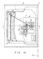
- an optical unit 2 is provided with an outer housing 6 and a base plate 8.
- the base plate 8 covers the outer housing 6 and seals the interior of the outer housing 6.
- the base plate 8 constitutes part of a laser beam printer.
- the optical unit 2 contains: a laser diode 12 for generating a laser beam L; a laser scanning device 4 made up of a first optical system 10 and a scanner 50 which are integrally arranged; and a second optical system 70.
- the first optical system 10 includes a group of conversion lenses, while the second optical system 70 includes a group of focusing lenses.
- the optical unit 2 further contains a monitoring optical device which monitors whether or not a laser beam L, guided through the first and second optical systems 10 and 70 and used for scanning a photosensitive body 90, is horizontally synchronized.
- the laser scanning device 4 is mounted on an insulating base 4a.
- This insulating base 4a need not be used if the outer housing 6 is formed of an insulating material.
- the laser diode 12 and at least one lens of the first optical system 10 are assembled in such a manner as to constitute a lens barrel.
- the laser beam L generated by the laser diode 12 is converged when it passes through the first optical system 10.
- the laser beam L is directed to the scanner 50, by which the laser beam L is reflected toward the photosensitive body 90, for scanning it at a nonunorm angular velocity.
- the laser beam L reflected by the scanner 50 is directed first to the second optical system 70.
- the laser beam L is focused on a desirable point on the surface of the photosensitive body 90 by the second optical system 70.
- the laser beam L moves over the photosensitive body 90 in the main scanning direction, with keeping the focused condition due to the second optical system 70, as the reflecting surface of the scanner 50 rotates.
- the distance over which the laser beam L moves in the main scanning direction from the center of the optical axis to a given point is made to correspond to the angle at which the surface of the scanner 50 rotates.
- the laser beam L, focused on the photosensitive body 90 is modified or ON-OFF controlled by additional units such as a beam modulator, a data input circuit, etc., (not shown) to form character data and/or graphics data on the surface of the photosensitive body 90. Therefore, an electrostatic latent image is formed on the surface of the photosensitive body 90.
- the photosensitive body 90 is rotated in a predetermined direction by a driver (not shown).
- the electrostatic latent image is formed in accordance with the rotation of the photosensitive body 90.
- the electrostatic latent image, thus formed, is developed by a developing means (not shown), and is then transferred onto a given transferring material (not shown).
- Part of the laser beam L passing through the second optical system 70 is reflected by a horizontal synchronization-detecting mirror (not shown) at each scan performed in the main scanning direction.
- the reflected laser beam L is guided to a synchronization signal detector (not shown), for the detection of horizontal synchronization.
- the first optical system 10 includes: a glass lens 14 which slightly converges the laser beam L produced by the laser diode 12; and first and second plastic lenses 16 and 18 which further converges the laser beam converged by the glass lens 14.
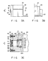
- the glass lens 14 is a convex lens formed of optical glass, such as BK7, SK10, etc. As is seen in Figs. 3A-3C, it has a flange 14a by means of which it is held to a housing 20 (lens barrel 30).
- the first plastic lens 16 is formed of, polymethyl methacrylate (PMMA), etc., and has toric surfaces. The toric surfaces have negative power in the main scanning direction and slightly-negative power in the sub-scanning direction.
- the first plastic lens 16 has a flange by means of which it is attached to a housing 20. It also has either a positioning-projection or a positioning-recess formed substantially at the center with respect to the main scanning direction.
- the second plastic lens 18 is formed of PMMA, etc. It has toric surfaces. The toric surfaces which have positive power in the main scanning direction and negative power in the sub-scanning direction.
- the second plastic lens 16 has a flange by means of which it is attached to the housing 20. It also has either a positioning-projection or a positioning-recess formed substantially at the center with respect to the main scanning direction.
- the scanner 50 includes a polygonal mirror 66 having a plurality of deflecting mirrors 68.
- Each deflecting mirror 68 which is convex in the main scanning direction, i.e., the deflecting mirror 68 is curved with a predetermined radius R of curvature.
- the number of deflecting mirrors 68 is four in this embodiment, but may be a multiple of four.
- the polygonal mirror 66 is driven by an axial gap type motor 60.
- This motor 60 is contains: a rotor 54 which is integral with the rotating shaft 52 of the motor 60; a direct bearing 56 which supports the rotating shaft 52 in such a manner as to allow smooth rotation; etc.
- the polygonal mirror 66 is reliably fixed to the rotor 54 by means of a stop ring 62 and a spring member 64.
- the second optical system 70 includes a third plastic lens 72 for focusing a laser beam L on the surface of the photosensitive body 90, and a dust-preventing cover 76 for sealing the above-mentioned optical members of the optical unit 2.
- H f ⁇ .
- the third plastic lens 72 functions as a kind of f ⁇ lens which has positive power and which is curved such that the power decreases in accordance with an increase in the deflection angle ⁇ with respect to the main scanning direction.
- the third plastic lens 72 is formed of PMMA, etc., and has either a positioning-projection or a positioning-recess (not shown) formed substantially in the center with respect to the main scanning direction.
- the dust-preventing cover 76 is a transparent glass or plastic plate. It is formed of optical plate, such as BK7, filter glass, PMMA, or the like. It has a thickness of 2-3 mm, and permits the laser beam L to pass therethrough. In order to cut off a light having such a wavelength as adversely affects the photosensitive body 90, the dust-preventing cover 76 may be provided with a sharp cut filter function.
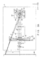
- the first optical system 10 and the second optical system 70 are arranged such that their optical axes form a predetermined angle in a plane expanding in the sub-scanning direction. This arrangement is adopted for the purpose of eliminating ghost laser beam l to be mentioned later.
- the laser diode 12 and lenses 14, 16 and 18 of the first optical system 10 are integrally assembled together and are held by the housing 20.
- the housing 20 contains the lens barrel 30 which will be detailed later with reference to Figs. 3A-3C.
- a stop 22 which restricts the intensity or amount of convergent laser beam L, and a first mirror 24 which is arranged between the first and second plastic lenses 16 and 18 to change the traveling direction of the laser beam L, are also held by the housing 20.
- a second mirror 74 is arranged between the third plastic lens 72 and the dust-preventing cover 76, so as to change the traveling direction of the laser beam L.
- the laser beam L generated by the laser diode 12 is converged or collimated by the glass lens 14.
- the laser beam L is shaped to have a predetermined cross section.
- the laser beam L emerging from the stop 22 is guided to the first plastic lens 16.
- the laser beam L is collimated in the main scanning direction and is converged in the sub-scanning direction.
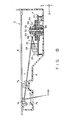
- the laser beam L, thus processed, is then directed to the second plastic lens 18 via the first mirror 24, as is seen in Figs. 1A and 1B.
- the laser beam L is converged in both the main scanning direction and sub-scanning direction.
- the laser beam L emerging from the second plastic lens 18 is directed to one deflecting mirror 68 of the polygonal mirror 66 of the scanner 50. After reflected by the deflecting mirror 68, the laser beam L is directed at a nonuniform angular velocity to the third plastic lens 72, which functions as a kind of f ⁇ lens, as mentioned above.
- the third plastic lens 72 suppresses the adverse effects caused by the field curve and corrects the distortion aberration to have a desirable value.
- the third plastic lens 72 corrects the positional shift of the laser beam L on the photosensitive body 90, even if each mirror 68 of the polygonal mirror 66 tilt.
- the laser beam L emerging from the third plastic lens 72 is directed to the photosensitive body 90 by way of the dust-preventing cover 76 which is mounted on the housing 6 of the optical unit 2.
- the lenses 14, 16, 18, and 72 and the scanner 50 used in the embodiment have such optical characteristics as are shown in Tables 1 and 2 below.
- Table 1 (Lens characteristics with respect to main scanning direction) First Focusing System Polygonal Mirror 66 Second Focusing System Glass lens 14 Lens 16 Lens 18 Lens 12 i - 1 2 3 4 5 Power P 0.0907035 -0.0134704 0.0134029 -0.025109855 9.92445 ⁇ 10 ⁇ 4 Focal Length f 11.0294 -74.2368 74.6107 -39.825 -1.00761 ⁇ 103
- Table 2 (Lens characteristics with respect to main scanning direction) First Focusing System Polygonal Mirror 66 Second Focusing System Glass lens 14 Lens 16 Lens 18 Lens 12 i - 1 2 3 4 5 Power P 0.0907035 -0.00094897 -0.0530289 0.0 -0.0221932 Focal Length f 11.0294 -1053.77 -18.8576 ⁇ 45.0588
- the glass lens 14 is secured to the lens barrel 30 by means of a push member 32 and an elastic member 34 for example a wave washer, etc.
- the push member 32 includes a cylindrical portion 32a and a screw portion 32b.
- the cylindrical portion 32a has a pressing part on that side which contacts the glass lens 14.
- the position of the glass lens 14 can be adjusted in the direction indicated by arrow A by turning the push member 32.
- the glass lens 14 has a flange 14a. Since this flange 14a and the pressing part of the cylindrical portion 32a are in line contact with each other, the torque required for turning the push member 32 is small.
- a hole 36 is formed in the push member 32.
- the laser diode 12 is fixed to a laser diode holder 40 by means of a screw 42.
- the position of the laser diode holder 40 can be adjusted in the directions indicated by arrows B and C, so that the laser diode holder 40 can be positioned in a desirable manner with reference to the lens barrel 30.
- the laser diode holder 40 is pressed against the lens barrel 30 with desirable pressure by means of a spring washer 44, a flat washer 46, and a screw 48.
- a laser beam L is generated from the laser-emitting point 12a of the diode laser 12.
- the laser beam L is converged by the glass lens 14 and restricted by the stop 22 located at the rear-focal plane of the glass lens 14, in such a manner that the laser beam L can form a beam spot of predetermined size. Thereafter, the laser beam L is directed to the photosensitive body 90.
- the stop 22 is located at a position away from the rear-focal plane of the glass lens L, for example, at the position 22b indicated by the broken lines in Fig. 5. In this case, the amount of laser beam L passing through the stop 22 is greatly varied depending upon the location of the laser-emiting point 12a of the laser diode 12.
- the amount of laser beam L passing through the stop 22 reduces approximately to half.
- the intensity or amount of laser beam L directed to the photosensitive body 90 can remain substantially unchanged, even if the direction in which the major component of the laser beam L generated by the laser diode 12 and the optical axis of the glass lens 14 are shifted from each other.
- the reflecting mirrors of the scanner will not be held accurately at an intended angle (i.e., a so-called mirror tilting problem). If this happens, the point H to which a laser beam is actually irradiated is shifted from the right position h , due to the curvature of the f ⁇ lens. As a result, the f ⁇ characteristics is adversely affected. In addition, the field curvature (i.e., image distortion at the point h to which the laser beam should be irradiated) is also adversely affected. In order to improve the f ⁇ characteristics and the field curvature, as well as other optical characteristics, the mirrors 68 of the polygonal mirror 66 are provided with an adequated curvature.
- the characteristics of the laser beam i.e., an image, irradiated onto the photosensitive body are adversely affected. That is, the f ⁇ characteristic, the field curve, the distortion aberration, etc., are adversely affected.
- the f ⁇ characteristic varies from "-" to "+” in accordance with an increase in the absolute value of the angle ⁇ of rotation of the mirror 68.
- the symbols "-" and “+” used with the f ⁇ characteristic indicate how H and h are related to each other in the Y-axis direction, i.e., in the main scanning direction ( ⁇ > 0). If H > h, the relationship is "+”, and if H ⁇ h, the relationship is "-”.
- the third plastic lens 72 should be an f ⁇ lens which is specially shaped such that the power of the center portion of the lens is smaller than that of the circumferential portion.
- the field curve is inevitably shifted to the side of the polygonal mirror 66, noted the symbol "+” in accordance with an increase in the angle of rotation of the mirror 68.
- the symbols "+” and “-" used with the field curve indicate the direction in which the focus of the laser beam L directed to the photosensitive body 90 is shifted from a given reference position. If the focus of the laser beam L is shifted from the reference position toward the interior of the photosensitive body 90, the shifting direction is represented by "-”. If the focus of the laser beam L is shifted from the reference position in the opposite direction, the shifting direction is represented by "+".
- the field curve and f ⁇ characteristic can be controlled to have adequate values with reference to the surface of the photosensitive body 90.
- Figs. 6 and 7 illustrate the reason why the ghost laser beam can be eliminated.
- a line which is normal to a mirror 68 and which passes through a deflection point C (0, 0, 0) is represented by vector CD
- an incident laser beam is represented by vector AC
- reflected laser beam obtained by projecting vector CB on an XZ plane is expressed as (-tan ⁇ , -sin2 ⁇ , -cos2 ⁇ ).
- a distance D between the Z axis and the optical axis 0 with respect to the position of the coordinates Z3 is determined by Z3 ⁇ tan ⁇ .
- the third plastic lens 72 is provided with a toric surface which can be rotated about an axis perpendicular to the main scanning plane, i.e., a Y axis.
- a laser beam when a laser beam is incident on the first surface of a third plastic lens, it is refracted at a certain angle in the main scanning direction.
- the laser beam passes through the second surface of the lens, it is refracted in a direction different from the incident laser beam, directed toward a photosensitive body.
- part of the laser beam incident on the first surface is reflected by the second surface and is returned to the first surface again. Then, the returned laser beam is reflected by the first surface. This laser beam which reflected twice is appears as a ghost laser beam falling on the photosensitive body.
- the third plastic lens 72 has different curvatures between the portion which is center in the main scanning direction and the portions which are peripheral in the main scanning direction.
- the third plastic lens 72 having these different curvatures is arranged such that the optical axis determined with respect to the sub-scanning direction is shifted toward the laser beam incident on each mirror 68.
- the laser beam L is incident on the third plastic lens 72, the center of which is shifted from the optical axis, such that the beam is shifted from both the optical axis, determined with respect to the sub-scanning direction, by a predetermined distance and the center of the lens 72.
- the laser beam L is incident on the first surface of the third plastic lens 72, it is refracted in the X-axis direction (sub-scaming direction) at a certain angle.
- the laser beam L emerges from the second surface of the third plastic lens 72, it is again refracted in a direction different from that in which it is refracted by the first surface, and is then directed to the photosensitive body 90.
- part of the laser beam L incident on the first surface is reflected by the second surface.
- the reflected laser beam ⁇ is reflected by the first surface again, is become a ghost laser beam l.
- the reflected laser beam ⁇ is reflected by the first surface such that it passes through focus F, due to the curvature which is determined for the first surface in the sub-scanning direction. Since the reflect laser beam ⁇ reflected by the first surface is guided in a different direction from that of the major component of the laser beam L, the ghost laser beam l is divided from the laser beam L. Therefore, the ghost laser beam l is eliminated from the surface of the photosensitive body 90 by adding a light shielding element (not shown).
- the third plastic lens 72 has different optical characteristics between the portion which is center in the main scanning direction and the portions which are peripheral in the main scanning direction.
- M denotes a central portion of the lens 72 in the main scanning direction
- N denotes the peripheral portions of the lens 72 where the angle of rotation of each mirror 68 will be larger
- S Mi denotes a surface portion which is center with respect to the main scanning direction and on which a laser beam L is incident
- S Ni denotes surface portions which are peripheral with respect to the main scanning direction and on which the laser beam L is incident
- S Mo and S No denote surface portions from which the laser beam L emerges
- f M and f N are focal lengths corresponding to the surface portions S Mi and S Ni , respectively
- r M and r N are radii determining the curvatures of the surface portions S Mi and S Ni , respectively.
- L M denotes a laser beam which passes through a portion located in the vicinity of the optical axis determined with respect to the main scanning direction
- L N denotes a laser beam which passes through peripheral portions determined with respect to the main scanning direction
- l M denotes a ghost laser beam produced by the laser beam L incident in the vicinity of the optical axis determined with respect to the main scanning direction
- l N denotes a ghost laser beam produced by the laser beam L incident on the peripheral portions determined with respect to the main scanning direction
- ⁇ M and ⁇ N denote angles at which the ghost laser beams l M and l N are inclined with reference to the major components of laser beams L M and L N .
- the inclination angles ⁇ M and ⁇ N are in inverse proportion to the radius r of curvature of each portion of the curved surface of the third plastic lens 72. Therefore, the inclination angle ⁇ M of the ghost laser beam l M is wide in the region where the value of r is small, i.e., the regions in the neighborhood of the center determined with respect to the main scanning direction, while the inclination angle ⁇ N of the ghost laser beam l N is narrow in the region where the value of r is large, i.e., the region in the neighborhood of the peripheral portions determined with respect to the main scanning direction.
- the inclination angles ⁇ M and ⁇ N are in proportion to the deviation of the intersection between the optical axis of the third plastic lens 72 and the laser beam L. Therefore, in the case where the third plastic lens 72 has its optical axis shifted in the direction of the displacement, the value of ⁇ X3 varies in accordance with a change in the rotating angle ⁇ of each mirror 68 of the polygonal mirror 66.
- is small in the portions where r is small, and is large in the portions where r is large.
- the optical axis of the third plastic lens 72 is shifted from the major component of the laser beam L, as mentioned above.
- the angle between the ghost laser beam l and the laser beam L is large if the absolute value of the displacement ⁇ X3 is large ( ⁇ X 3N ), and is narrow if the absolute value of the displacement ⁇ X3 is small ( ⁇ X 3M ).
- the distance ⁇ X3 ( ⁇ X 3N ) between the major component of the laser beam passing through the third plastic lens 72 and the optical axis of the third plastic lens 72 is long in the region where the angle ⁇ of rotation of each mirror 68 of the polygonal mirror 66 is large, whereas the distance ⁇ X3 ( ⁇ X 3M ) between the major component of the laser beam passing through the third plastic lens 72 and optical axis 0′ of the third plastic lens 72 is small in the region of the lens center.
- the ghost laser beam l (l M , l N ) can be eliminated from even all surface of the third plastic lens 72 while simultaneously suppressing the shifting of the third plastic lens 72.
- the angle of incidence at which the laser beam L is incident on the third plastic lens 72 is considered substantially 0°. Therefore, the sectional shape of the laser-emerging side of the third plastic lens 72 can be substantially flat in the sub-scanning direction.
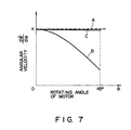
- the graph shown in Fig. 7 shows how the field curve and the f ⁇ characteristic are corrected by setting an optimal deflection angular velocity.
- the deflection angular speed is determined by the angle ⁇ of rotation of the polygonal mirror 66 or the mirror 68 and by the angle ⁇ formed between the major component of the laser beam L and the optical axis 0 of the third plastic lens 72.
- the deflection angular velocity (d ⁇ /d ⁇ ) obtained by this formula II is represented by the curve in Fig. 7.
- straight line A in Fig. 7 corresponds to the case where the mirrors 68 of the scanner 50 are flat
- curve B corresponds to the case where the mirrors 68 of the scanner 50 are convex, as in the present invention.
- the third plastic lens 72 incorporated in the optical unit is a kind of an f ⁇ lens.
- the deflection angular velocity of the polygonal mirror 66 is determined in accordance with the characteristics of the third plastic lens 72 in such a manner that it falls within the region between curves C and B in Fig. 7 (curve C: a curve which is as similar as possible to straight line A).
- curve C a curve which is as similar as possible to straight line A.
- the improvement of both the field curve and the f ⁇ characteristic are simultaneously achieved by determining the deflection angular velocity d ⁇ /d ⁇ in accordance with the correction characteristics of the third plastic lens 72 such that the deflection angular velocity is within the region between curves C and B.
- Figs. 8A and 8B show how the field curve and the f ⁇ characteristic are improved by the deflection angular velocity d ⁇ /d ⁇ is satisfy.
- curves a represent the characteristics obtained when the polygonal mirror 66 is used alone, while curves b represent the characteristics obtained when the polygonal mirror 66 and the third plastic lens 72 are used in combination.
- both the f ⁇ characteristic and the field curve can be simultaneously improved by combining the scanner including convex mirrors with a kind of f ⁇ lens having a toric surface.
- the adverse effects which may be caused by mirror tilting are eliminated, so that a laser beam scanning the surface of the photosensitive body is prevented from swaying or wavering.
- the second optical system is only required to include a single lens, the size of the entire optical unit can be small. It should be also noted that the cost needed to manufacture the optical system can be remarkably reduced since the f ⁇ lens is a plastic lens which can be easily formed with high precision.
Landscapes
- Physics & Mathematics (AREA)
- Engineering & Computer Science (AREA)
- Multimedia (AREA)
- Signal Processing (AREA)
- General Physics & Mathematics (AREA)
- Optics & Photonics (AREA)
- Mechanical Optical Scanning Systems (AREA)
- Laser Beam Printer (AREA)
- Lenses (AREA)
Applications Claiming Priority (2)
| Application Number | Priority Date | Filing Date | Title |
|---|---|---|---|
| JP254911/89 | 1989-09-29 | ||
| JP1254911A JPH03116112A (ja) | 1989-09-29 | 1989-09-29 | 走査式光学装置 |
Publications (2)
| Publication Number | Publication Date |
|---|---|
| EP0420124A2 true EP0420124A2 (de) | 1991-04-03 |
| EP0420124A3 EP0420124A3 (en) | 1992-03-18 |
Family
ID=17271563
Family Applications (1)
| Application Number | Title | Priority Date | Filing Date |
|---|---|---|---|
| EP19900118343 Withdrawn EP0420124A3 (en) | 1989-09-29 | 1990-09-24 | Optical unit for use in laser beam printer or the like |
Country Status (3)
| Country | Link |
|---|---|
| US (1) | US5095383A (de) |
| EP (1) | EP0420124A3 (de) |
| JP (1) | JPH03116112A (de) |
Cited By (1)
| Publication number | Priority date | Publication date | Assignee | Title |
|---|---|---|---|---|
| EP0703088A3 (de) * | 1994-08-29 | 1998-01-28 | Konica Corporation | Bilderzeugungsvorrichtung mit optischer Zweistrahlabtasteinheit |
Families Citing this family (14)
| Publication number | Priority date | Publication date | Assignee | Title |
|---|---|---|---|---|
| US5247383A (en) * | 1990-03-20 | 1993-09-21 | Olive Tree Technology, Inc. | Scanner with a post facet lens system |
| JPH05346549A (ja) * | 1992-04-17 | 1993-12-27 | Canon Inc | 走査光学装置 |
| US5442477A (en) * | 1993-02-04 | 1995-08-15 | Asahi Kogaku Kogyo Kabushiki Kaisha | Optical scanning system |
| US5375132A (en) * | 1993-05-05 | 1994-12-20 | Coherent, Inc. | Solid state laser with interleaved output |
| JP3242238B2 (ja) * | 1993-10-27 | 2001-12-25 | ブラザー工業株式会社 | 記録装置 |
| JPH07287165A (ja) * | 1994-04-15 | 1995-10-31 | Nec Corp | 光学系 |
| JPH1013630A (ja) * | 1996-06-21 | 1998-01-16 | Asahi Optical Co Ltd | スキャナ |
| US6897405B2 (en) * | 2001-11-30 | 2005-05-24 | Matsushita Electric Industrial Co., Ltd. | Method of laser milling using constant tool path algorithm |
| JP4430855B2 (ja) * | 2002-07-23 | 2010-03-10 | Hoya株式会社 | 走査光学系 |
| US6836284B2 (en) * | 2003-04-01 | 2004-12-28 | Tri-Star Technologies | Laser marking using a digital micro-mirror device |
| US7403316B2 (en) | 2004-01-14 | 2008-07-22 | Ricoh Company, Ltd. | Optical scanning device, image forming apparatus and liquid crystal device driving method |
| JP4801410B2 (ja) | 2005-10-07 | 2011-10-26 | 株式会社リコー | 光走査装置及び画像形成装置 |
| JP6388383B2 (ja) * | 2014-08-04 | 2018-09-12 | 船井電機株式会社 | レーザレンジファインダ |
| US10067222B2 (en) | 2014-08-01 | 2018-09-04 | Funai Electric Co., Ltd. | Laser rangefinder |
Family Cites Families (6)
| Publication number | Priority date | Publication date | Assignee | Title |
|---|---|---|---|---|
| US3961838A (en) * | 1975-01-10 | 1976-06-08 | Zygo Corporation | Apparatus for producing a scanning laser beam of constant linear velocity |
| JPS60133414A (ja) * | 1983-12-22 | 1985-07-16 | Ricoh Co Ltd | ポストオブジエクテイブ型光偏向器 |
| JPS61156020A (ja) * | 1984-12-28 | 1986-07-15 | Ricoh Co Ltd | ポストオブジエクテイブ型光偏向器 |
| JP2502314B2 (ja) * | 1987-07-06 | 1996-05-29 | 株式会社テック | ポストオブジェクティブ型光偏向器 |
| DE3887610T2 (de) * | 1987-09-22 | 1994-08-25 | Tokyo Electric Co Ltd | Hinter einem Objektiv angeordneter optischer Ablenker. |
| US4984857A (en) * | 1989-01-17 | 1991-01-15 | Iowa State University Research Foundation, Inc. | Linearization of scan velocity of resonant vibrating-mirror beam deflectors |
-
1989
- 1989-09-29 JP JP1254911A patent/JPH03116112A/ja active Pending
-
1990
- 1990-09-24 EP EP19900118343 patent/EP0420124A3/en not_active Withdrawn
- 1990-09-25 US US07/587,726 patent/US5095383A/en not_active Expired - Fee Related
Cited By (1)
| Publication number | Priority date | Publication date | Assignee | Title |
|---|---|---|---|---|
| EP0703088A3 (de) * | 1994-08-29 | 1998-01-28 | Konica Corporation | Bilderzeugungsvorrichtung mit optischer Zweistrahlabtasteinheit |
Also Published As
| Publication number | Publication date |
|---|---|
| JPH03116112A (ja) | 1991-05-17 |
| EP0420124A3 (en) | 1992-03-18 |
| US5095383A (en) | 1992-03-10 |
Similar Documents
| Publication | Publication Date | Title |
|---|---|---|
| EP0016630B1 (de) | Vorrichtung zur optischen Abtastung | |
| CA1087006A (en) | Optical system for rotating mirror line scanning apparatus | |
| EP0853253B1 (de) | Optisches Abtastgerät | |
| EP0420124A2 (de) | Optische Einheit verwendbar für Laserdrucker oder ähnliche Apparate | |
| EP0386226B1 (de) | Optische abtastvorrichtung | |
| US4099829A (en) | Flat field optical scanning system | |
| EP0415236B1 (de) | Optische Einheit für die Verwendung in einem Laserstrahldrucker oder dergleichen | |
| KR100335624B1 (ko) | 레이저빔주사장치 | |
| EP0433953B1 (de) | F-theta-Linse und diese Linse enthaltendes optisches Abtastsystem | |
| US5159193A (en) | Optical unit for use in laser beam printer or the like with temperature expansion compensation | |
| EP0431603B1 (de) | Optische Einheit für einen Laserdrucker | |
| US4962982A (en) | Light beam scanning device and light beam scanning lens | |
| EP0658787B1 (de) | Abtastlinse und optisches Abtastsystem mit einer solchen Linse | |
| EP0441350B1 (de) | Optisches System zur Abtastung mit Lichtstrahlen | |
| US5124830A (en) | Optical deflector device for deflecting laser beam | |
| EP0415234A2 (de) | Optische Einheit für Laserstrahldrucker oder dergleichen | |
| JP3556706B2 (ja) | ラスタ出力スキャナ画像形成システム | |
| US5142404A (en) | Optical unit for use in laser beam printer or the like | |
| EP0018787A1 (de) | Optisches Abtastgerät | |
| US5381259A (en) | Raster output scanner (ROS) using an overfilled polygon design with minimized optical path length | |
| JP2996679B2 (ja) | 光学装置 | |
| JP2907292B2 (ja) | 色消しレーザ走査光学系 | |
| JP3192537B2 (ja) | 走査光学装置 | |
| JP2928553B2 (ja) | 走査式光学装置 | |
| JP3150320B2 (ja) | 光学装置 |
Legal Events
| Date | Code | Title | Description |
|---|---|---|---|
| PUAI | Public reference made under article 153(3) epc to a published international application that has entered the european phase |
Free format text: ORIGINAL CODE: 0009012 |
|
| 17P | Request for examination filed |
Effective date: 19901019 |
|
| AK | Designated contracting states |
Kind code of ref document: A2 Designated state(s): DE FR GB |
|
| PUAL | Search report despatched |
Free format text: ORIGINAL CODE: 0009013 |
|
| AK | Designated contracting states |
Kind code of ref document: A3 Designated state(s): DE FR GB |
|
| STAA | Information on the status of an ep patent application or granted ep patent |
Free format text: STATUS: THE APPLICATION HAS BEEN WITHDRAWN |
|
| 18W | Application withdrawn |
Withdrawal date: 19920714 |