EP0420126A1 - Dispositif de prélèvement sanguin - Google Patents
Dispositif de prélèvement sanguin Download PDFInfo
- Publication number
- EP0420126A1 EP0420126A1 EP90118345A EP90118345A EP0420126A1 EP 0420126 A1 EP0420126 A1 EP 0420126A1 EP 90118345 A EP90118345 A EP 90118345A EP 90118345 A EP90118345 A EP 90118345A EP 0420126 A1 EP0420126 A1 EP 0420126A1
- Authority
- EP
- European Patent Office
- Prior art keywords
- piston rod
- piston
- rear end
- locking
- insert
- Prior art date
- Legal status (The legal status is an assumption and is not a legal conclusion. Google has not performed a legal analysis and makes no representation as to the accuracy of the status listed.)
- Granted
Links
- 238000010241 blood sampling Methods 0.000 title abstract description 8
- 238000005070 sampling Methods 0.000 claims abstract description 35
- 238000000605 extraction Methods 0.000 claims description 29
- 239000008280 blood Substances 0.000 claims description 19
- 210000004369 blood Anatomy 0.000 claims description 19
- 238000012360 testing method Methods 0.000 claims description 15
- 238000000034 method Methods 0.000 claims description 4
- 230000015572 biosynthetic process Effects 0.000 claims 1
- 210000003462 vein Anatomy 0.000 description 7
- 238000013461 design Methods 0.000 description 5
- 239000007788 liquid Substances 0.000 description 4
- 230000000903 blocking effect Effects 0.000 description 2
- 238000009423 ventilation Methods 0.000 description 2
- 208000003443 Unconsciousness Diseases 0.000 description 1
- 230000009286 beneficial effect Effects 0.000 description 1
- 230000015556 catabolic process Effects 0.000 description 1
- 230000000295 complement effect Effects 0.000 description 1
- 230000006835 compression Effects 0.000 description 1
- 238000007906 compression Methods 0.000 description 1
- 230000000694 effects Effects 0.000 description 1
- 230000002349 favourable effect Effects 0.000 description 1
- 238000009434 installation Methods 0.000 description 1
- 238000012423 maintenance Methods 0.000 description 1
- 238000004519 manufacturing process Methods 0.000 description 1
- 238000000926 separation method Methods 0.000 description 1
- 239000000126 substance Substances 0.000 description 1
- 238000012549 training Methods 0.000 description 1
- 238000013022 venting Methods 0.000 description 1
Images

Classifications
-
- A—HUMAN NECESSITIES
- A61—MEDICAL OR VETERINARY SCIENCE; HYGIENE
- A61B—DIAGNOSIS; SURGERY; IDENTIFICATION
- A61B5/00—Measuring for diagnostic purposes; Identification of persons
- A61B5/15—Devices for taking samples of blood
- A61B5/153—Devices specially adapted for taking samples of venous or arterial blood, e.g. with syringes
-
- A—HUMAN NECESSITIES
- A61—MEDICAL OR VETERINARY SCIENCE; HYGIENE
- A61B—DIAGNOSIS; SURGERY; IDENTIFICATION
- A61B5/00—Measuring for diagnostic purposes; Identification of persons
- A61B5/15—Devices for taking samples of blood
- A61B5/150007—Details
- A61B5/150015—Source of blood
- A61B5/15003—Source of blood for venous or arterial blood
-
- A—HUMAN NECESSITIES
- A61—MEDICAL OR VETERINARY SCIENCE; HYGIENE
- A61B—DIAGNOSIS; SURGERY; IDENTIFICATION
- A61B5/00—Measuring for diagnostic purposes; Identification of persons
- A61B5/15—Devices for taking samples of blood
- A61B5/150007—Details
- A61B5/150206—Construction or design features not otherwise provided for; manufacturing or production; packages; sterilisation of piercing element, piercing device or sampling device
- A61B5/150236—Pistons, i.e. cylindrical bodies that sit inside the syringe barrel, typically with an air tight seal, and slide in the barrel to create a vacuum or to expel blood
-
- A—HUMAN NECESSITIES
- A61—MEDICAL OR VETERINARY SCIENCE; HYGIENE
- A61B—DIAGNOSIS; SURGERY; IDENTIFICATION
- A61B5/00—Measuring for diagnostic purposes; Identification of persons
- A61B5/15—Devices for taking samples of blood
- A61B5/150007—Details
- A61B5/150206—Construction or design features not otherwise provided for; manufacturing or production; packages; sterilisation of piercing element, piercing device or sampling device
- A61B5/150244—Rods for actuating or driving the piston, i.e. the cylindrical body that sits inside the syringe barrel, typically with an air tight seal, and slides in the barrel to create a vacuum or to expel blood
-
- A—HUMAN NECESSITIES
- A61—MEDICAL OR VETERINARY SCIENCE; HYGIENE
- A61B—DIAGNOSIS; SURGERY; IDENTIFICATION
- A61B5/00—Measuring for diagnostic purposes; Identification of persons
- A61B5/15—Devices for taking samples of blood
- A61B5/150007—Details
- A61B5/150374—Details of piercing elements or protective means for preventing accidental injuries by such piercing elements
- A61B5/150381—Design of piercing elements
- A61B5/150473—Double-ended needles, e.g. used with pre-evacuated sampling tubes
- A61B5/150496—Details of construction of hub, i.e. element used to attach the double-ended needle to a piercing device or sampling device
-
- A—HUMAN NECESSITIES
- A61—MEDICAL OR VETERINARY SCIENCE; HYGIENE
- A61B—DIAGNOSIS; SURGERY; IDENTIFICATION
- A61B5/00—Measuring for diagnostic purposes; Identification of persons
- A61B5/15—Devices for taking samples of blood
- A61B5/150007—Details
- A61B5/150885—Preventing re-use
- A61B5/150908—Preventing re-use by disconnecting components, e.g. breaking or rupturing of connected parts, e.g. piston and rod
-
- A—HUMAN NECESSITIES
- A61—MEDICAL OR VETERINARY SCIENCE; HYGIENE
- A61B—DIAGNOSIS; SURGERY; IDENTIFICATION
- A61B5/00—Measuring for diagnostic purposes; Identification of persons
- A61B5/15—Devices for taking samples of blood
- A61B5/150007—Details
- A61B5/150885—Preventing re-use
- A61B5/150916—Preventing re-use by blocking components, e.g. piston, driving device or fluid passageway
-
- A—HUMAN NECESSITIES
- A61—MEDICAL OR VETERINARY SCIENCE; HYGIENE
- A61B—DIAGNOSIS; SURGERY; IDENTIFICATION
- A61B5/00—Measuring for diagnostic purposes; Identification of persons
- A61B5/15—Devices for taking samples of blood
- A61B5/150007—Details
- A61B5/150206—Construction or design features not otherwise provided for; manufacturing or production; packages; sterilisation of piercing element, piercing device or sampling device
- A61B5/150259—Improved gripping, e.g. with high friction pattern or projections on the housing surface or an ergonometric shape
-
- A—HUMAN NECESSITIES
- A61—MEDICAL OR VETERINARY SCIENCE; HYGIENE
- A61B—DIAGNOSIS; SURGERY; IDENTIFICATION
- A61B5/00—Measuring for diagnostic purposes; Identification of persons
- A61B5/15—Devices for taking samples of blood
- A61B5/150007—Details
- A61B5/150374—Details of piercing elements or protective means for preventing accidental injuries by such piercing elements
- A61B5/150381—Design of piercing elements
- A61B5/150389—Hollow piercing elements, e.g. canulas, needles, for piercing the skin
-
- A—HUMAN NECESSITIES
- A61—MEDICAL OR VETERINARY SCIENCE; HYGIENE
- A61B—DIAGNOSIS; SURGERY; IDENTIFICATION
- A61B5/00—Measuring for diagnostic purposes; Identification of persons
- A61B5/15—Devices for taking samples of blood
- A61B5/150007—Details
- A61B5/150374—Details of piercing elements or protective means for preventing accidental injuries by such piercing elements
- A61B5/150534—Design of protective means for piercing elements for preventing accidental needle sticks, e.g. shields, caps, protectors, axially extensible sleeves, pivotable protective sleeves
- A61B5/150572—Pierceable protectors, e.g. shields, caps, sleeves or films, e.g. for hygienic purposes
Definitions
- the invention relates to a blood sampling device according to the preamble of patent claim 1.
- Blood sampling devices are only intended for blood sampling but not for injecting any liquid substances into a patient's vein, but are generally suitable for this.
- the piston rod is provided with a plurality of serrations which cooperate with resilient locking lugs provided on the bottom of the syringe.
- the syringe By rotating the piston rod by 90 °, the syringe can be pulled open and the liquid drawn out can then be expelled, for example into a patient's vein. Since further rotation of the piston rod is prevented by engaging the pawl in a radial recess of the piston rod, this syringe can also be used only for drawing up and expelling liquid once.
- a blood collection device (US Pat. No. 4,370,987) is already known, the piston rod of which is provided with teeth and the rear wall of which is provided with an opening for the passage of the piston rod and with a stop lug arranged therein.
- the rear sharpened end of a cannula inserted into the patient's vein can be inserted through an elastic stopper located at the front end of the sampling tube, whereby the vacuum inside the cannula becomes effective and blood from the patient's vein sucks into the sampling tube.
- the opening provided in the rear wall for the passage of the piston rod must be so large that the teeth on the piston rod and the stop lug can be disengaged, which makes it possible to move the piston forward, too is also intended to expel the blood taken into another container.
- the known device could also be misused as a syringe.
- the invention is therefore based on the device, which is fundamentally also suitable for taking blood, according to US Pat. No. 4,826,483, in which the piston rod is guided in the axial direction relative to the sampling tube in such a way that the locking means are not disengaged by radial movements of the piston rod can, but only by turning the piston rod.
- the invention has for its object to provide a blood collection device of the type mentioned, its use as Syringe is excluded so that deliberate misuse of the blood collection device as a syringe is effectively prevented.
- a movement of the piston in the direction of the front end of the sampling tube is at most possible to the extent that a certain, but extremely short, path of the piston has to be covered in this direction in order to bring about the locking means, for example consisting of a locking toothing and a locking tongue cooperating therewith .
- the forward movement of the piston required for engaging the locking means should be as small as possible and in particular so small that at most a part of the blood in the cannula is pushed back into the vein, but not some of the contents of the sampling tube itself.
- An advantageous embodiment is designed so that the locking means are arranged between the piston rod and the rear end of the sampling tube.
- the locking means consists of at least one locking toothing running along the piston rod and arranged thereon and at least one locking stop cooperating therewith at the rear end of the extraction tube.
- the locking teeth should be so fine that a substantial forward movement of the piston for engaging the locking stop in the locking teeth is not required.
- the design can be such that the teeth of the locking teeth are unyielding and the locking stop is a pawl resiliently biased to the locking teeth.
- the teeth of the locking teeth are spring lobes which extend obliquely forward and away from the piston rod and which cooperate with a fixed locking step which represents the locking stop and runs transversely to the longitudinal extension of the piston rod.
- the design is expedient so that the locking step begins at such a radial distance from the piston rod that the spring tabs pressed against the piston rod can pass through the gap between the piston rod and the locking step.
- a particularly reliable locking is achieved if the locking step merges at a radial distance from its beginning into a wall which extends to the rear and which prevents the spring tab snapped directly behind the locking step when the piston rod is pushed forward from a radial expansion which cancels the locking effect .
- This training is particularly favorable in the case of a one-piece design of the extraction tube end, because then the attachment of a resilient pawl could be problematic there.
- the resilient tabs on the piston rod can easily be attached during the manufacturing process.
- the locking means consists of a one-sided clamping ratchet arranged at the end of the extraction tube and the opposite, preferably roughened surface of the piston rod.
- the clamping ratchet enables the piston or the piston rod to be fixed in the sense that practically no forward movement of the piston or the piston rod is required for the locking means to become effective.
- the invention provides, according to a first alternative, that the rotation lock is formed by engaging the latching teeth in a radial recess provided with side flanks and arranged in a rotationally fixed manner relative to the extraction tube, or that the Piston rod has a non-circular cross section, which is guided through a correspondingly non-circular guide opening at the rear end of the sampling tube.
- a preferred embodiment of the invention provides that the part of the locking means provided at the rear end of the collection tube is insertable into an insert in the rear end of the collection tube and the passage opening for the piston rod is provided, which can be fixed in the end of the sampling tube in such a way that when the piston rod is pulled out and pushed in or into the sampling tube, the insert remains in its fixed position.
- the insert can preferably be snapped into the rear end of the sampling tube, in particular in such a way that manipulations by means of a tool mean that the insert can no longer be removed from the rear end of the sampling tube without being destroyed. In this way, any improper use of the blood collection device according to the invention as a syringe is effectively avoided.
- the insert is only provided on one side of the piston rod. However, it is preferably provided that the insert extends around the piston rod.
- the insert is divided into two halves and can thus be folded around the piston rod, or the design is such that the insert can be used by locking means which have been rendered ineffective by a tool Piston side can be pushed onto the piston rod, although the piston can be temporarily removed, for example by unscrewing.
- the invention is used with particular advantage in a blood sampling device with a front end of the sampling tube closed by a pierceable elastic plate, the elastic plate preferably being provided in an attachment of a screw cap screwed on the front of the sampling tube (DE-C2-29 48 653).
- a guide sleeve with a cannula sharpened on both sides is then pushed onto the attachment, the rear end of the cannula piercing the elastic plate.
- a preferred method for carrying out a vacuum test is characterized in that the backward movement of the piston required for the vacuum test when the piston has not yet been inserted into the rear end of the sampling tube, but is preferably already above the rear one Ren end of the piston rod arranged insert takes place and the insert is brought into the mounted position defined at the rear end of the sampling tube only after the piston has been pushed after or during the vacuum test into its front end position.
- the vacuum test is preferably carried out in such a way that the piston is first moved so far forward when the front end of the sampling tube is vented that the insert is not yet fixed at the rear end of the sampling tube, in particular snapped into place, so that the front end of the sampling tube is then sealed is that the piston is then retracted a bit and preferably released again, in order to monitor its return to the original position more or less when the vacuum is generated, and that when the vacuum test is successful, the insert is fixed, in particular latched, at the rear end of the sampling tube.
- the vacuum test can also be carried out by briefly withdrawing the piston. After the vacuum test, by moving the piston forward, the space provided in front of the piston of the sampling tube is vented, e.g. by briefly unscrewing a front screw cap.
- these measures can be combined with the attachment of the insert, in that the insert has not yet been inserted into the rear end of the sampling tube during the vacuum test by retracting the piston and is preferably already arranged over the rear end of the piston rod, and in that the Use for subsequent venting by pushing the piston in or onto the rear end of the sampling tube in the assembled position is pressed, in particular a projection on the piston rod or the rearmost tooth of the locking teeth or the handle at the end of the piston rod transmits the pressure force to the insert.
- the insert is inserted into the rear end of the extraction tube in the same operation as the ventilation of the interior.
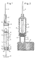
- a circular cylindrical extraction tube 11 is screwed onto an external thread at its front end te screw cap 25, from which extends forward according to FIGS. 1 and 2, an extension 26 in which a pierceable elastic plate 22 is arranged.
- a guide sleeve 27 with a circular cylindrical interior can be pushed onto the circular-cylindrical hollow extension 26, which carries at its front end a cannula 12 sharpened on both sides, the rear part 12a of which is covered by an elastic hose 28.
- Axial ventilation grooves 43 are provided in the outer lateral surface of the extension 26.
- a piston 15 is axially slidably and tightly arranged, into which a piston rod 14 is screwed in from 39, which on one side according to FIGS. 1 and 3 is parallel to the axis of the piston rod 14 extending detent teeth 16 carries, the teeth 41 have at their front end a substantially perpendicular to the piston rod 14 extending locking surface 23 and fall obliquely back to the piston rod 14.
- an annular insert 20 is inserted into the rear end of the extraction tube 11, which has an axial guide opening 13 for the piston rod 14 and is also provided with a resilient pawl 17 opposite the locking teeth 16.
- the teeth of the locking teeth 16 and the pawl 17 are inclined so that when the piston rod 14 is pulled out of the removal tube 11, the pawl 17 can snap from tooth to tooth, while trying to move the piston rod 14 in the direction of the screw cap 25, the pawl 17 is pressed against the locking surface 23 of the tooth 41 of the locking toothing 16 located there, as a result of which the movement of the piston rod 14 is blocked in this direction.
- the piston rod 14 is guided in the guide opening 13 so that it cannot move away from the pawl 17.
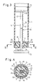
- the guide opening 13 according to FIGS.
- the through opening at 13a is somewhat larger, in order to create sufficient space axially to the rear for the pawl 17 for the locking teeth 16 to pass through.
- the pawl 17 is relaxed in the basic position shown in Fig. 3, so that it is not at the level of the ratchet teeth. In this way, the pawl 17 does not lose its spring force even if the blood collection device is stored for a long time.
- the insert 20 On the radially outside, the insert 20 has latching projections 29 which engage behind counter-latches 30 projecting inwards at the rear end of the removal tube 11.
- the locking projections 29 and the counter detents 30 just have a reverse locking action as the locking teeth 16 and the pawl 17, ie that the insert 20 can be inserted in the direction of the screw cap 25 from behind into the extraction tube 11 and locked there while pulling axially of use 20 after is prevented at the rear by the locking projections 29 cooperating with the counter-locking 30.
- radial incisions 31 can be provided, into which radial webs 32 of the insert 20 engage in the removal tube 11 for the purpose of securing the insert 20 against rotation.
- Such a rotation lock is required if - as shown in FIGS. 1, 3 and 4 - the locking teeth 16 and the pawl 17 are only provided on one side of the piston rod 14. Any other rotation lock can also be used for the insert 20, which ensures that the locking teeth 16 and the pawl 17 always remain in alignment.
- the insert 20 is fixed relative to the removal tube 11 and the piston rod 14 relative to the insert in predetermined rotational positions.
- diametrically opposite sides of the piston rod 14 are provided with a roughened surface 19.
- the insert 20 is formed by a wedge-shaped recesses 35 'tapered forward complementary wedges 36 arranged locking mechanism.
- the radial inner surfaces of the wedges 36 are in frictional engagement with the surface 19 of the piston rod 14 by being pushed forward by springs 37. If the piston rod 14 is pulled away from the screw cap 25, the wedges 36 become detached from them tapered wedge surfaces 35 in the direction of the screw cap 25. Retracting the piston rod 14 is therefore possible.
- the piston rod 14 is displaced in the direction of the screw cap 25, the wedges 36 wedge between the wedge surfaces 35 of the insert 20 and the surfaces 19 of the piston rod 14. This wedging supports the action of the springs 37, which the wedges 36 from behind press against the tapered wedge surfaces 35.
- the wedges 36 also taper towards the front and, in addition to the inner clamping surfaces adapted to the surface of the piston rod 14, have wedge surfaces adapted to the outside of the conical surfaces 35. With the piston rod 14 roughened all around, clamping wedges 36 could also be provided around the piston rod 14.
- the annular insert 20 if it is formed in one piece and according to FIGS. 1, 3, is first applied to the rear region of the piston rod 14 in the manner described below.
- Either the insert 20 is then already snapped over the rearmost tooth 41 ′′′ before it snaps into the rear end of the rear end of the extraction tube 11 according to FIG. 1, or it remains on the piston rod piece between the rear end of the locking toothing 16 and that at the end of the piston rod 14 provided handle 24.
- the piston 15 with the piston rod 14 and the insert 20 located thereon is then pushed into the extraction tube 11 from behind, but only to the extent that the insert 20 still protrudes from the rear end of the extraction tube 11 and is not locked therein.
- the screw cap 25 is then screwed on and the vacuum test is carried out by withdrawing the piston rod 14, by releasing the piston after a certain retraction movement and checking how far it moves back into its starting position due to the vacuum generated. If there is a leak somewhere, the piston will not return to its original position after it has been released, and the sampling tube in question can either be repaired or viewed as a scrap. If the vacuum test was successful, the insert 20 is pushed forward until it snaps into the rear end of the sampling tube 11. This should expediently only take place when the piston 15 is in the foremost position in the extraction tube 11. If the pawl 17 has already snapped behind the rearmost tooth 41 ′′′ (FIG.
- the insert 20 can also be pushed forward by pushing the piston rod 14 in, but this should be brought about by briefly unscrewing the screw caps 25.
- the insert 20 is arranged freely displaceably between the handle 24 and the toothing 16, because in this way the piston 15 can first be brought into the foremost position while the screw cap 25 is still unscrewed, and then the screw cap 25 screwed on and the vacuum test is carried out in the manner described above. The insert can then be snapped into the rear end of the extraction tube 11 separately with the piston 15 already in its final position.
- the procedure for taking blood is as follows:
- the guide sleeve 27 is pushed onto the extension 26 (FIG. 2), the rear part 12a of the cannula 12 piercing the elastic plate 22. Now the vein can be punctured and 15 blood can be drawn by pulling back the plunger.
- the pawl 17 snaps according to FIG. 1 from tooth to tooth of the locking toothing 16.
- the handle 24 is released or if an attempt is made to move it in the opposite direction towards the screw cap 25, this is not possible because the pawl 17 engages in the tooth 41 of the locking toothing 16 that has just been assigned.
- FIG. 5 where the locking wedges 36 prevent a reversal of movement of the piston rod 14 in the direction of the screw cap 25.
- the invention is also suitable for building up a vacuum by retracting the piston rod 14 before the guide sleeve 27 is placed on the extension 26. While in known blood sampling devices of this type the piston only engages in a counter-latching of the sampling tube 11 in the fully retracted state, locking according to the invention takes place even when the piston 15 is only slightly retracted, so that the build-up of the vacuum can be interrupted in any retracted position of the piston 15 . In this way it is possible to build up a vacuum which is not as strong as is achieved when the piston 15 is fully retracted, which e.g. may be beneficial in patients with poor and sensitive veins. In this way, the amount of blood drawn during a vacuum withdrawal can also be limited in the desired manner. A breakdown of the vacuum, for example by conscious or unconscious advancement of the piston, is not possible due to the blocking means according to the invention.
- the invention thus not only prevents the piston 15 from being moved backwards or forwards, but also enables a precisely measured build-up and maintenance of a desired vacuum within the extraction tube 11.
- the insert 20 in a particularly simple manner, provided that it runs around the piston rod 14 according to the illustrated exemplary embodiments, it can be divided into two parts according to FIG. 4 along an axial separation surface 21, which are suitably arranged before assembly the piston rod 14 are put around.
- the piston rod can also have a non-circular cross section which is guided through a correspondingly non-round guide opening 13 in the insert 20, as a result of which a perfect angular position of the piston rod 14 relative to the insert 20 is ensured.
- the piston rod 14 screwed in at 39 as shown in FIG. 1 can be unscrewed, for which purpose the piston 15 should be locked in a manner not shown at the rear end of the extraction tube 11.
- the area 40 in front of the locking teeth 16 must be designed in cross-section such that, when the piston 15 is completely retracted, the piston rod 14 can be rotated relative to the fixed piston 15.
- the piston 15 is locked in its most retracted position by the fact that the foremost tooth 41 'of the locking teeth 16 snaps behind the pawl 17 and that the piston rod 14 at a predetermined breaking point provided behind the first tooth 41' 42 is canceled.
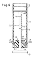
- the toothing 16 provided on the piston rod 14 consists of spring tabs 41 Feder arranged one behind the other on the piston rod 14, which extend at equal intervals from the piston rod 14 to the front and away from it.
- the spring tabs 41 ⁇ are designed to be pressure-resistant, but can deflect radially inwards towards the piston rod 14.
- a rigid annular step 17 'projecting radially inwards into the free space 13a is provided on the insert 20 in the region of the toothing 16, which has a distance 43 from the piston rod 14 that when the piston rod is withdrawn 14 the spring tab 41 ⁇ can spring under compression through the distance 43 corresponding gap to finally snap behind the ring step 17 ', as is shown for the rearmost spring tab in Fig. 6.
Landscapes
- Health & Medical Sciences (AREA)
- Life Sciences & Earth Sciences (AREA)
- Engineering & Computer Science (AREA)
- Heart & Thoracic Surgery (AREA)
- Molecular Biology (AREA)
- Pathology (AREA)
- Physics & Mathematics (AREA)
- Biomedical Technology (AREA)
- Hematology (AREA)
- Medical Informatics (AREA)
- Biophysics (AREA)
- Surgery (AREA)
- Animal Behavior & Ethology (AREA)
- General Health & Medical Sciences (AREA)
- Public Health (AREA)
- Veterinary Medicine (AREA)
- Manufacturing & Machinery (AREA)
- Measurement Of The Respiration, Hearing Ability, Form, And Blood Characteristics Of Living Organisms (AREA)
- Infusion, Injection, And Reservoir Apparatuses (AREA)
Applications Claiming Priority (2)
| Application Number | Priority Date | Filing Date | Title |
|---|---|---|---|
| DE3932109A DE3932109A1 (de) | 1989-09-26 | 1989-09-26 | Blutentnahmevorrichtung |
| DE3932109 | 1989-09-26 |
Publications (2)
| Publication Number | Publication Date |
|---|---|
| EP0420126A1 true EP0420126A1 (fr) | 1991-04-03 |
| EP0420126B1 EP0420126B1 (fr) | 1994-12-14 |
Family
ID=6390220
Family Applications (1)
| Application Number | Title | Priority Date | Filing Date |
|---|---|---|---|
| EP90118345A Expired - Lifetime EP0420126B1 (fr) | 1989-09-26 | 1990-09-24 | Dispositif de prélèvement sanguin |
Country Status (3)
| Country | Link |
|---|---|
| US (2) | US5095914A (fr) |
| EP (1) | EP0420126B1 (fr) |
| DE (2) | DE3932109A1 (fr) |
Cited By (7)
| Publication number | Priority date | Publication date | Assignee | Title |
|---|---|---|---|---|
| EP0484579A1 (fr) * | 1990-11-07 | 1992-05-13 | Wadley Technologies, Inc. | Stabilisation de spécimens pour analyse microbiologique |
| WO2009144085A2 (fr) | 2008-04-18 | 2009-12-03 | Kuros Biosurgery Ag | Dispositif de distribution, ensemble contenant le dispositif, et procédé d'utilisation du dispositif |
| EP2143454A1 (fr) | 2008-07-07 | 2010-01-13 | Kuros Biosurgery AG | Dispositif distributeur, kit contenant le dispositif et procédé de fonctionnement du dispositif |
| WO2013191659A1 (fr) * | 2012-06-21 | 2013-12-27 | Beng Teck See | Seringue modifiée |
| EP2968791A4 (fr) * | 2013-03-15 | 2016-10-19 | Merit Medical Systems Inc | Ensembles seringues verrouillables et dispositifs et procédés associés |
| CN113883983A (zh) * | 2021-09-26 | 2022-01-04 | 中国十七冶集团有限公司 | 一种快速测量起拱高度的检测装置及操作方法 |
| US11350945B2 (en) | 2017-11-13 | 2022-06-07 | Merit Medical Systems, Inc. | Staged deflation syringe systems and associated methods |
Families Citing this family (26)
| Publication number | Priority date | Publication date | Assignee | Title |
|---|---|---|---|---|
| US4979944A (en) * | 1989-08-21 | 1990-12-25 | The Pullman Company | Surgical vacuum evacuation device |
| US5265621A (en) * | 1992-03-31 | 1993-11-30 | Simpson Shawn L | Apparatus for sampling blood |
| US5380295A (en) * | 1992-12-14 | 1995-01-10 | Mallinckrodt Medical, Inc. | Delivery apparatus with mechanism preventing rearward movement of a piston disposed therein |
| FR2739779B1 (fr) * | 1995-10-17 | 1998-01-09 | Emerit Michel | Seringue d'aspiration et dispositif d'aspiration comprenant une telle seringue |
| US5951491A (en) * | 1998-01-13 | 1999-09-14 | Wu; Tan | Syringe for drawing blood |
| DE19936294A1 (de) * | 1999-08-02 | 2001-02-15 | Hans Mueller | Spritze |
| DE20110872U1 (de) * | 2001-06-30 | 2002-11-07 | Medizintechnik Promedt GmbH, 25436 Tornesch | Blutentnahmespritze |
| US20040116830A1 (en) * | 2001-08-24 | 2004-06-17 | Trudeau William M | Blood testing deivce |
| US7063673B2 (en) * | 2003-01-23 | 2006-06-20 | Becton Dickinson And Company | Coupling device for blood collection assembly |
| DE20301575U1 (de) * | 2003-01-31 | 2003-06-05 | Sarstedt AG & Co., 51588 Nümbrecht | Blutentnahmevorrichtung mit einem eine Kanüle aufweisenden Halter |
| US20050187532A1 (en) * | 2004-02-24 | 2005-08-25 | Medex, Inc. | Diaphragm-based reservoir for a closed blood sampling system |
| US20060018799A1 (en) * | 2004-07-21 | 2006-01-26 | Wong Cai Ne W | Universal tissue homogenizer device and methods |
| US7600105B2 (en) * | 2004-09-22 | 2009-10-06 | Cyberlink Corp. | Systems, methods, and apparatus for providing efficient startup to computers with peripheral devices |
| DE102004056655B4 (de) * | 2004-11-23 | 2007-03-29 | Sarstedt Ag & Co. | Probenröhrchen zur Aufnahme von Körperflüssigkeit, insbesondere Blut |
| US7740636B2 (en) * | 2005-04-15 | 2010-06-22 | Abbott Medical Optics Inc. | Multi-action device for inserting an intraocular lens into an eye |
| US8267911B2 (en) * | 2007-06-08 | 2012-09-18 | Smiths Medical Asd, Inc. | Flow-through fluid reservoir |
| USD594117S1 (en) | 2007-06-08 | 2009-06-09 | Smiths Medical Asd, Inc. | Flow-through medical fluid reservoir |
| US20090018548A1 (en) * | 2007-07-13 | 2009-01-15 | Charles Steven T | Pneumatically-Powered Intraocular Lens Injection Device with Removable Cartridge |
| ES2822304T3 (es) | 2008-11-26 | 2021-04-30 | Becton Dickinson Co | Jeringa de un solo uso con desactivación automática |
| ES2437541B1 (es) * | 2012-07-03 | 2014-11-25 | Biotechnology Institute, I Mas D, S.L. | Dispositivo para la extracción, el almacenamiento y/o el procesado de sangre u otras sustancias de origen humano o animal, y para la aplicación de compuestos sanguíneos u otros compuestos biológicos |
| US10300481B2 (en) * | 2015-06-17 | 2019-05-28 | Patrick Pennie | Centrifuge tube assembly for separating, concentrating and aspirating constituents of a fluid product |
| US10182939B2 (en) | 2015-09-16 | 2019-01-22 | Novartis Ag | Hydraulic injector and methods for intra-ocular lens insertion |
| CN112423804B (zh) * | 2018-07-18 | 2023-07-18 | 英赛罗公司 | 药物递送插入设备和系统 |
| EP4061221A1 (fr) * | 2019-11-22 | 2022-09-28 | Université catholique de Louvain | Dispositif de prélèvement et traitement d'un échantillon |
| FR3119546B1 (fr) * | 2021-02-09 | 2026-04-03 | Aptar France Sas | Applicateur à micro-aiguilles |
| US20230191033A1 (en) | 2021-12-17 | 2023-06-22 | Kurin, Inc. | Syringes configured to inhibit forward plunger movement |
Citations (4)
| Publication number | Priority date | Publication date | Assignee | Title |
|---|---|---|---|---|
| DE643616C (de) * | 1935-03-08 | 1937-04-13 | Hauptner Fa H | Impfspritze, insbesondere fuer tieraerztlichen Gebrauch |
| US4367738A (en) * | 1981-10-28 | 1983-01-11 | Janssen Pharmaceutica Inc. | Pre-filled syringe for abusable drugs |
| EP0208975A2 (fr) * | 1985-07-04 | 1987-01-21 | Antonio Gomez Gomez | Seringue destinée à produire un vide contrôlé |
| DE3811973C1 (fr) * | 1988-04-11 | 1989-08-03 | Michael Dipl.-Ing. 4403 Senden De Greive |
Family Cites Families (20)
| Publication number | Priority date | Publication date | Assignee | Title |
|---|---|---|---|---|
| US201443A (en) * | 1878-03-19 | Improvement in hypodermic syringes | ||
| DE12528C (de) * | F. tommasi in Paris | Elektrische Lampe. | ||
| US2369304A (en) * | 1944-07-18 | 1945-02-13 | Lewis Everett Marion | Hypodermic syringe |
| DE2328718C3 (de) * | 1973-06-06 | 1981-02-05 | Walter Sarstedt Kunststoff-Spritzgusswerk, 5223 Nuembrecht | Blutentnahmevorrichtung |
| DE3026281C2 (de) * | 1974-11-29 | 1984-09-20 | Walter Sarstedt Kunststoff-Spritzgußwerk, 5223 Nümbrecht | Blutentnahmevorrichtung |
| US4246898A (en) * | 1979-07-23 | 1981-01-27 | Cutter Laboratories, Inc. | Syringe |
| DE2948653C2 (de) * | 1979-12-04 | 1984-01-05 | Walter Sarstedt Kunststoff-Spritzgußwerk, 5223 Nümbrecht | Blutentnahmevorrichtung |
| US4370987A (en) * | 1980-10-07 | 1983-02-01 | Seymour Bazell | Medical fluid collection device |
| DE3049503C2 (de) * | 1980-12-30 | 1983-04-28 | Walter Sarstedt Kunststoff-Spritzgußwerk, 5223 Nümbrecht | "Blutentnahmevorrichtung" |
| US4333457A (en) * | 1981-02-09 | 1982-06-08 | Sterling Drug Inc. | Self-aspirating syringe with frictionally engaged locking collet |
| AU552883B2 (en) * | 1981-11-03 | 1986-06-26 | Walter Sarstedt Kunststoff-Spritzgusswerk | Blood extracting and centrifuging device |
| JPS6130699U (ja) * | 1984-07-26 | 1986-02-24 | 三菱鉛筆株式会社 | 注入器 |
| GB2203047B (en) * | 1987-02-27 | 1991-01-30 | Gilbert Henry Banks | Single-use syringe |
| US4832696A (en) * | 1987-03-05 | 1989-05-23 | Luther Medical Products, Inc. | Assembly of needle and protector |
| FR2618075A1 (fr) * | 1987-07-17 | 1989-01-20 | Assistance Publique | Seringue de haute securite non reutilisable |
| DE8804656U1 (de) * | 1988-04-08 | 1988-08-04 | Bader, Mohandes, 2350 Neumünster | Medizinische Spritze |
| US4826483A (en) * | 1988-05-05 | 1989-05-02 | Paul F. Boyd | Non-reusable syringe |
| CH669910A5 (en) * | 1988-07-05 | 1989-04-28 | Michel Elie Ritzi | Syringe with two series of stops on piston - engageable by rotation with slot in cover to allow motion in one direction only |
| FR2634650B1 (fr) * | 1988-08-01 | 1990-11-02 | Labouze Joseph | Seringue non reutilisable |
| US4906231A (en) * | 1988-10-14 | 1990-03-06 | Young J Winslow | Single-use fillable syringe |
-
1989
- 1989-09-26 DE DE3932109A patent/DE3932109A1/de not_active Withdrawn
-
1990
- 1990-09-24 DE DE59008004T patent/DE59008004D1/de not_active Expired - Fee Related
- 1990-09-24 EP EP90118345A patent/EP0420126B1/fr not_active Expired - Lifetime
- 1990-09-25 US US07/587,697 patent/US5095914A/en not_active Expired - Lifetime
-
1992
- 1992-01-30 US US07/828,392 patent/US5174301A/en not_active Expired - Lifetime
Patent Citations (4)
| Publication number | Priority date | Publication date | Assignee | Title |
|---|---|---|---|---|
| DE643616C (de) * | 1935-03-08 | 1937-04-13 | Hauptner Fa H | Impfspritze, insbesondere fuer tieraerztlichen Gebrauch |
| US4367738A (en) * | 1981-10-28 | 1983-01-11 | Janssen Pharmaceutica Inc. | Pre-filled syringe for abusable drugs |
| EP0208975A2 (fr) * | 1985-07-04 | 1987-01-21 | Antonio Gomez Gomez | Seringue destinée à produire un vide contrôlé |
| DE3811973C1 (fr) * | 1988-04-11 | 1989-08-03 | Michael Dipl.-Ing. 4403 Senden De Greive |
Cited By (10)
| Publication number | Priority date | Publication date | Assignee | Title |
|---|---|---|---|---|
| EP0484579A1 (fr) * | 1990-11-07 | 1992-05-13 | Wadley Technologies, Inc. | Stabilisation de spécimens pour analyse microbiologique |
| WO2009144085A2 (fr) | 2008-04-18 | 2009-12-03 | Kuros Biosurgery Ag | Dispositif de distribution, ensemble contenant le dispositif, et procédé d'utilisation du dispositif |
| US8469233B2 (en) | 2008-04-18 | 2013-06-25 | Kuros Biosurgery Ag | Dispensing device, kit containing the device, and method of operating the device |
| EP2143454A1 (fr) | 2008-07-07 | 2010-01-13 | Kuros Biosurgery AG | Dispositif distributeur, kit contenant le dispositif et procédé de fonctionnement du dispositif |
| WO2013191659A1 (fr) * | 2012-06-21 | 2013-12-27 | Beng Teck See | Seringue modifiée |
| EP2968791A4 (fr) * | 2013-03-15 | 2016-10-19 | Merit Medical Systems Inc | Ensembles seringues verrouillables et dispositifs et procédés associés |
| US9561327B2 (en) | 2013-03-15 | 2017-02-07 | Merit Medical Systems, Inc. | Lockable syringe assemblies and related devices and methods |
| US11350945B2 (en) | 2017-11-13 | 2022-06-07 | Merit Medical Systems, Inc. | Staged deflation syringe systems and associated methods |
| CN113883983A (zh) * | 2021-09-26 | 2022-01-04 | 中国十七冶集团有限公司 | 一种快速测量起拱高度的检测装置及操作方法 |
| CN113883983B (zh) * | 2021-09-26 | 2023-09-22 | 中国十七冶集团有限公司 | 一种快速测量起拱高度的检测装置及操作方法 |
Also Published As
| Publication number | Publication date |
|---|---|
| US5095914A (en) | 1992-03-17 |
| DE59008004D1 (de) | 1995-01-26 |
| DE3932109A1 (de) | 1991-04-11 |
| US5174301A (en) | 1992-12-29 |
| EP0420126B1 (fr) | 1994-12-14 |
Similar Documents
| Publication | Publication Date | Title |
|---|---|---|
| EP0420126B1 (fr) | Dispositif de prélèvement sanguin | |
| DE3874571T2 (de) | Krankheitsueberwachungsspritze mit zurueckschiebbarer nadel. | |
| DE2909002C3 (de) | Injektionsspritze für einmalige Verwendung | |
| DE3049503C2 (de) | "Blutentnahmevorrichtung" | |
| DE69110050T2 (de) | Sicherheitsspritze mit zurückziehbarer hohlnadel. | |
| DE68910778T2 (de) | Blutsammel- und/oder -einspritzgerät und beidseitig gespritzte Nadel und Halterung dafür. | |
| DE60000038T2 (de) | Injektionsvorrichtung für Einmalverwendung | |
| DE2513397C2 (de) | Hohlzylindrischer Patronenhalter für eine Injektionsspritze | |
| DE69022066T2 (de) | Spritze mit zurückziehbarer nadelhalterung. | |
| EP0412968B1 (fr) | Seringue, notamment a usage medical | |
| DE2434046C3 (de) | Nadelhalterung für medizinische Spritzen | |
| DE69008850T2 (de) | Spritze mit auswechselbarer und zurückziehbarer kanülenplattform. | |
| DE19821933C1 (de) | Vorrichtung zur Verabreichung eines injizierbaren Produkts | |
| EP1032445B1 (fr) | Procede et dispositif de commande de la profondeur de penetration d'une aiguille pour injection | |
| DE2744439C2 (de) | Einweg-Injektionsspritze | |
| EP1180381B1 (fr) | Cathéter intraveineux muni d'une gaine de protection | |
| DE69428981T2 (de) | Spritze für subkutaninjektionen mit einer zurückziehbaren nadel | |
| DE69813050T2 (de) | Spritzvorrichtung mit Schutzhülle | |
| EP2954914A1 (fr) | Dispositif d'injection, notamment auto-injecteur comprenant une protection contre la piqûre involontaire et/ou une sécurité contre la surcharge, pour un réservoir à produit | |
| DE1491788A1 (de) | Injektor fuer Medikamente | |
| EP0648511A2 (fr) | Seringue d'injection | |
| DE29912965U1 (de) | Injektionsvorrichtung | |
| DE3740269A1 (de) | Blutentnahmevorrichtung | |
| EP2702943B1 (fr) | Dispositif de prélèvement de liquides corporels et procédé de montage d'un tel dispositif | |
| DE69316611T2 (de) | Einwegspritze |
Legal Events
| Date | Code | Title | Description |
|---|---|---|---|
| PUAI | Public reference made under article 153(3) epc to a published international application that has entered the european phase |
Free format text: ORIGINAL CODE: 0009012 |
|
| AK | Designated contracting states |
Kind code of ref document: A1 Designated state(s): DE FR GB IT |
|
| 17P | Request for examination filed |
Effective date: 19910816 |
|
| 17Q | First examination report despatched |
Effective date: 19931229 |
|
| GRAA | (expected) grant |
Free format text: ORIGINAL CODE: 0009210 |
|
| AK | Designated contracting states |
Kind code of ref document: B1 Designated state(s): DE FR GB IT |
|
| PG25 | Lapsed in a contracting state [announced via postgrant information from national office to epo] |
Ref country code: IT Free format text: LAPSE BECAUSE OF FAILURE TO SUBMIT A TRANSLATION OF THE DESCRIPTION OR TO PAY THE FEE WITHIN THE PRE;WARNING: LAPSES OF ITALIAN PATENTS WITH EFFECTIVE DATE BEFORE 2007 MAY HAVE OCCURRED AT ANY TIME BEFORE 2007. THE CORRECT EFFECTIVE DATE MAY BE DIFFERENT FROM THE ONE RECORDED.SCRIBED TIME-LIMIT Effective date: 19941214 Ref country code: FR Effective date: 19941214 Ref country code: GB Effective date: 19941214 |
|
| REF | Corresponds to: |
Ref document number: 59008004 Country of ref document: DE Date of ref document: 19950126 |
|
| EN | Fr: translation not filed | ||
| GBV | Gb: ep patent (uk) treated as always having been void in accordance with gb section 77(7)/1977 [no translation filed] |
Effective date: 19941214 |
|
| PLBE | No opposition filed within time limit |
Free format text: ORIGINAL CODE: 0009261 |
|
| STAA | Information on the status of an ep patent application or granted ep patent |
Free format text: STATUS: NO OPPOSITION FILED WITHIN TIME LIMIT |
|
| 26N | No opposition filed | ||
| PGFP | Annual fee paid to national office [announced via postgrant information from national office to epo] |
Ref country code: DE Payment date: 20030724 Year of fee payment: 14 |
|
| PG25 | Lapsed in a contracting state [announced via postgrant information from national office to epo] |
Ref country code: DE Free format text: LAPSE BECAUSE OF NON-PAYMENT OF DUE FEES Effective date: 20050401 |