EP0420168A2 - Procédé pour la fabrication d'une connexion détachable pour un ruban de fibres optiques et connexion ainsi obtenue - Google Patents
Procédé pour la fabrication d'une connexion détachable pour un ruban de fibres optiques et connexion ainsi obtenue Download PDFInfo
- Publication number
- EP0420168A2 EP0420168A2 EP90118439A EP90118439A EP0420168A2 EP 0420168 A2 EP0420168 A2 EP 0420168A2 EP 90118439 A EP90118439 A EP 90118439A EP 90118439 A EP90118439 A EP 90118439A EP 0420168 A2 EP0420168 A2 EP 0420168A2
- Authority
- EP
- European Patent Office
- Prior art keywords
- punch
- ridges
- ribbon
- fibres
- grinding
- Prior art date
- Legal status (The legal status is an assumption and is not a legal conclusion. Google has not performed a legal analysis and makes no representation as to the accuracy of the status listed.)
- Withdrawn
Links
Images


Classifications
-
- G—PHYSICS
- G02—OPTICS
- G02B—OPTICAL ELEMENTS, SYSTEMS OR APPARATUS
- G02B6/00—Light guides; Structural details of arrangements comprising light guides and other optical elements, e.g. couplings
- G02B6/24—Coupling light guides
- G02B6/36—Mechanical coupling means
- G02B6/3628—Mechanical coupling means for mounting fibres to supporting carriers
- G02B6/3684—Mechanical coupling means for mounting fibres to supporting carriers characterised by the manufacturing process of surface profiling of the supporting carrier
- G02B6/3696—Mechanical coupling means for mounting fibres to supporting carriers characterised by the manufacturing process of surface profiling of the supporting carrier by moulding, e.g. injection moulding, casting, embossing, stamping, stenciling, printing, or with metallic mould insert manufacturing using LIGA or MIGA techniques
-
- B—PERFORMING OPERATIONS; TRANSPORTING
- B23—MACHINE TOOLS; METAL-WORKING NOT OTHERWISE PROVIDED FOR
- B23Q—DETAILS, COMPONENTS, OR ACCESSORIES FOR MACHINE TOOLS, e.g. ARRANGEMENTS FOR COPYING OR CONTROLLING; MACHINE TOOLS IN GENERAL CHARACTERISED BY THE CONSTRUCTION OF PARTICULAR DETAILS OR COMPONENTS; COMBINATIONS OR ASSOCIATIONS OF METAL-WORKING MACHINES, NOT DIRECTED TO A PARTICULAR RESULT
- B23Q1/00—Members which are comprised in the general build-up of a form of machine, particularly relatively large fixed members
-
- B—PERFORMING OPERATIONS; TRANSPORTING
- B29—WORKING OF PLASTICS; WORKING OF SUBSTANCES IN A PLASTIC STATE IN GENERAL
- B29C—SHAPING OR JOINING OF PLASTICS; SHAPING OF MATERIAL IN A PLASTIC STATE, NOT OTHERWISE PROVIDED FOR; AFTER-TREATMENT OF THE SHAPED PRODUCTS, e.g. REPAIRING
- B29C59/00—Surface shaping of articles, e.g. embossing; Apparatus therefor
- B29C59/002—Component parts, details or accessories; Auxiliary operations
-
- B—PERFORMING OPERATIONS; TRANSPORTING
- B29—WORKING OF PLASTICS; WORKING OF SUBSTANCES IN A PLASTIC STATE IN GENERAL
- B29C—SHAPING OR JOINING OF PLASTICS; SHAPING OF MATERIAL IN A PLASTIC STATE, NOT OTHERWISE PROVIDED FOR; AFTER-TREATMENT OF THE SHAPED PRODUCTS, e.g. REPAIRING
- B29C59/00—Surface shaping of articles, e.g. embossing; Apparatus therefor
- B29C59/02—Surface shaping of articles, e.g. embossing; Apparatus therefor by mechanical means, e.g. pressing
- B29C59/022—Surface shaping of articles, e.g. embossing; Apparatus therefor by mechanical means, e.g. pressing characterised by the disposition or the configuration, e.g. dimensions, of the embossments or the shaping tools therefor
-
- G—PHYSICS
- G02—OPTICS
- G02B—OPTICAL ELEMENTS, SYSTEMS OR APPARATUS
- G02B6/00—Light guides; Structural details of arrangements comprising light guides and other optical elements, e.g. couplings
- G02B6/24—Coupling light guides
- G02B6/36—Mechanical coupling means
- G02B6/38—Mechanical coupling means having fibre to fibre mating means
- G02B6/3807—Dismountable connectors, i.e. comprising plugs
- G02B6/3833—Details of mounting fibres in ferrules; Assembly methods; Manufacture
- G02B6/3834—Means for centering or aligning the light guide within the ferrule
- G02B6/3838—Means for centering or aligning the light guide within the ferrule using grooves for light guides
- G02B6/3839—Means for centering or aligning the light guide within the ferrule using grooves for light guides for a plurality of light guides
-
- G—PHYSICS
- G02—OPTICS
- G02B—OPTICAL ELEMENTS, SYSTEMS OR APPARATUS
- G02B6/00—Light guides; Structural details of arrangements comprising light guides and other optical elements, e.g. couplings
- G02B6/24—Coupling light guides
- G02B6/36—Mechanical coupling means
- G02B6/38—Mechanical coupling means having fibre to fibre mating means
- G02B6/3807—Dismountable connectors, i.e. comprising plugs
- G02B6/3873—Connectors using guide surfaces for aligning ferrule ends, e.g. tubes, sleeves, V-grooves, rods, pins, balls
- G02B6/3885—Multicore or multichannel optical connectors, i.e. one single ferrule containing more than one fibre, e.g. ribbon type
-
- G—PHYSICS
- G02—OPTICS
- G02B—OPTICAL ELEMENTS, SYSTEMS OR APPARATUS
- G02B6/00—Light guides; Structural details of arrangements comprising light guides and other optical elements, e.g. couplings
- G02B6/24—Coupling light guides
- G02B6/36—Mechanical coupling means
- G02B6/3628—Mechanical coupling means for mounting fibres to supporting carriers
- G02B6/3648—Supporting carriers of a microbench type, i.e. with micromachined additional mechanical structures
- G02B6/3652—Supporting carriers of a microbench type, i.e. with micromachined additional mechanical structures the additional structures being prepositioning mounting areas, allowing only movement in one dimension, e.g. grooves, trenches or vias in the microbench surface, i.e. self aligning supporting carriers
-
- Y—GENERAL TAGGING OF NEW TECHNOLOGICAL DEVELOPMENTS; GENERAL TAGGING OF CROSS-SECTIONAL TECHNOLOGIES SPANNING OVER SEVERAL SECTIONS OF THE IPC; TECHNICAL SUBJECTS COVERED BY FORMER USPC CROSS-REFERENCE ART COLLECTIONS [XRACs] AND DIGESTS
- Y10—TECHNICAL SUBJECTS COVERED BY FORMER USPC
- Y10T—TECHNICAL SUBJECTS COVERED BY FORMER US CLASSIFICATION
- Y10T29/00—Metal working
- Y10T29/49—Method of mechanical manufacture
- Y10T29/49002—Electrical device making
- Y10T29/49117—Conductor or circuit manufacturing
- Y10T29/49194—Assembling elongated conductors, e.g., splicing, etc.
- Y10T29/49195—Assembling elongated conductors, e.g., splicing, etc. with end-to-end orienting
-
- Y—GENERAL TAGGING OF NEW TECHNOLOGICAL DEVELOPMENTS; GENERAL TAGGING OF CROSS-SECTIONAL TECHNOLOGIES SPANNING OVER SEVERAL SECTIONS OF THE IPC; TECHNICAL SUBJECTS COVERED BY FORMER USPC CROSS-REFERENCE ART COLLECTIONS [XRACs] AND DIGESTS
- Y10—TECHNICAL SUBJECTS COVERED BY FORMER USPC
- Y10T—TECHNICAL SUBJECTS COVERED BY FORMER US CLASSIFICATION
- Y10T29/00—Metal working
- Y10T29/49—Method of mechanical manufacture
- Y10T29/49002—Electrical device making
- Y10T29/49117—Conductor or circuit manufacturing
- Y10T29/49204—Contact or terminal manufacturing
- Y10T29/49208—Contact or terminal manufacturing by assembling plural parts
- Y10T29/4921—Contact or terminal manufacturing by assembling plural parts with bonding
-
- Y—GENERAL TAGGING OF NEW TECHNOLOGICAL DEVELOPMENTS; GENERAL TAGGING OF CROSS-SECTIONAL TECHNOLOGIES SPANNING OVER SEVERAL SECTIONS OF THE IPC; TECHNICAL SUBJECTS COVERED BY FORMER USPC CROSS-REFERENCE ART COLLECTIONS [XRACs] AND DIGESTS
- Y10—TECHNICAL SUBJECTS COVERED BY FORMER USPC
- Y10T—TECHNICAL SUBJECTS COVERED BY FORMER US CLASSIFICATION
- Y10T29/00—Metal working
- Y10T29/49—Method of mechanical manufacture
- Y10T29/49789—Obtaining plural product pieces from unitary workpiece
-
- Y—GENERAL TAGGING OF NEW TECHNOLOGICAL DEVELOPMENTS; GENERAL TAGGING OF CROSS-SECTIONAL TECHNOLOGIES SPANNING OVER SEVERAL SECTIONS OF THE IPC; TECHNICAL SUBJECTS COVERED BY FORMER USPC CROSS-REFERENCE ART COLLECTIONS [XRACs] AND DIGESTS
- Y10—TECHNICAL SUBJECTS COVERED BY FORMER USPC
- Y10T—TECHNICAL SUBJECTS COVERED BY FORMER US CLASSIFICATION
- Y10T29/00—Metal working
- Y10T29/49—Method of mechanical manufacture
- Y10T29/49826—Assembling or joining
- Y10T29/49906—Metal deforming with nonmetallic bonding
Definitions
- the present invention relates to a connecting group for ribbon optical fibres and to a process for making the same.
- each optical fiber of a ribbon forming one cable in alignment with the corresponding fiber of a ribbon forming the other cable, so as to allow light to pass from one fiber to the other while minimising dispersions and attenuations of the transmitted signal resulting from faults in the fiber alignment.
- the end of the ribbon itself is conveniently fitted into a rigid body, named connector, which keeps the fibres in a geometrically definite position; two connectors forming a pair are therefore arranged and held in a confronting relationship and aligned in order to form a connecting group, so that the respective fibres can take the correct position for forming the optical connection.
- opitcal fibres are housed within the grooves of a plate made of crystalline material which are obtained during several steps by localised etching, at positions defined by protection templates.
- Grooved plates can also be made using a metallic material by cold plastic deformation or coining; this working ensures a precise reproduction of the features of the punch used and therefore the achievement of the desired accuracy level is bound to the manufacture accuracy of the punch itself.
- the present invention aims at providing a process for making a punch having size accuracy and tolerances adapted for use in forming connector plates for ribbon-joined optical fibres by cold plastic deformation, which process involves relatively reduced costs as far as mechanical workings are concerned.
- each connector being mounted at one end of a respective optical fiber ribbon formed of at least two parallel optical fibres enclosed in a single outer coating, and being provided with a coupling face in contact with the corresponding face of another connector, the fibres being in alignment with each other and on which coupling face the end of the optical fibres of the respective ribbon come out, characterised in that a punch having several parallel ridges of dihedral form is manufactured by mechanical working, which ridges are symmetrically disposed relative to a middle plane passing through a longitudinal axis of the punch, the mechanical working comprising at least a grinding step for the parallel ridges in which corresponding ridges are worked in succession by rotating the punch about its longitudinal axis; several plates of metallic material having respective grooves corresponding the the punch ridges are cold pressed by plastic deformation; the fibres of an optical fiber ribbon are clamped between two plates, at least one of which is manufactured by means of
- the punch is made by first forming, by medium precision mechanical working, a partially-formed impression surface having several raised ridges in register with the desired position for the grooved plate grooves, then fastening the punch itself to the rotatable spindle of an angular precision index head mounted on one slide horizontally movable along a rectilinear guide perpendicular to a translation guide for the displacement of a second slide carrying a shaped-disc grinding machine, and thereafter performing the following steps: - grinding one side of a punch ridge by a first displacement of the slide carrying the grinding machine; - rotating the angular index head carrying the punch through 180°, while keeping its position steady along the translation guide and then, by a translation of the slide carrying the grinding machine, grinding the side of the punch ridge symmetrical to the preceding one with respect to a plane passing through the axis of rotation of the angular index head; - translating the slide carrying the angular index head towards the grinding machine by a predetermined working feed amount and repeating the preceding workings
- a further object of the present invention is to provide a punch for making metal plates by plastic deformation for interchangeable connectors for cables consisting of ribbon-joined optical fibres, characterised in that it has an impression surface having several parallel ridges designed to form corresponding grooves in the metal plates formed by said punch, which grooves are adapted to house one or more optical fibres and at least an alignment plug, wherein the ridges are symmetrical to a plane passing through the longitudinal axis of the punch, manufactured in accordance with the above described process.
- an interchangeable connector for cables consisting of ribbon-joined optical fibres, characterised in that it comprises at least a grooved plate wherein the grooves are adapted to house one or more optical fibres and at least an alignment plug and are symmetrical to a middle plane of the plate, the plate being formed by plastic deformation with a punch manufactured by adopting the above described process.
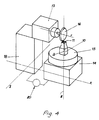
- connection of two optical fiber ribbons is carried out by means of a pair of connectors 1, 2, integral to the corresponding ends of optical fiber ribbons 3, 4, arranged in faced relationship.
- Each connector shown in an exploded view in the figure, consists of a pair of plates 5, at least one of which is provided with longitudinal grooves 6, inside which the ends of the optical fibres belonging to ribbons 3, 4 are arranged after being stripped, over a length thereof, of their protection coating made of plastic material, so that their cladding is exposed; a recess 7 formed at the end of the plate allows the end portion of the plastics coating greater in thickness to be accommodated.
- a pair of further longitudinal grooves 8 receives the plugs 9, preferably one for each connector, designed to enter the corresponding grooves of the other connector and through which the connectors are matched, the alignment condition of the connection being also determined by them.
- the plate grooves determining the position of the fibres and the alignment plugs are made by plastic deformation of the plate material by cold pressing or coining.
- plates 5 are pressed or coined by the use of a punch 10 having a working area 11 and therefore they appear strictly identical with one another; in a subsequent step the formation of the recess 7 takes place and for it tolerances of normal mechanical working are allowed.
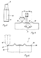
- the punch 10 is fastened to the work spindle of the index head 15, its axis a being coincident with the axis of rotation z of the index head.
- a grinding wheel 16 having an angled peripheral profile is supported by a grinding head 17, the axis of rotation r of which is horizontal and parallel to axis x; the grinding head 17 is carried by a slide 18 movable in the horizontal plane along axis y, perpendicular to axis x.
- Punch 10 is first worked using ordinary machine tools of the medium precision type that is exhibiting a precision in the range of ⁇ 1/10 of millimetre, thus forming the profile 19 shown in chain dot line in Fig. 6 on its working area 11, which profile substantially corresponds to the ultimate desired profile shown in solid line in the same figure, leaving a machining allowance to be removed by grinding, which has been magnified in the figure for the sake of clarity.
- the quantity of material to be removed by grinding will therefore be within reduced limits which will bring about unperceivable values of wear of the grinding wheel 16 during working.
- the punch is mounted on the index head 15 so that its axis is coincident with the axis of rotation z of the index head and the ridges of the profile 19 are parallel to the axis of horizontal translation y of the grinding head 17.
- a comparator 20 adapted to ensure a measurement precision in the range of ⁇ 1/100 of millimetre is associated with the slide 14 movable along axis x and carrying the angular index head 15 and executes the measurement of the translation thereof relative to the slide 18 carrying the grinding head 17.
- comparator 20 when starting working the slide 14 is disposed so that the action line of the profile apex of the grinding wheel 16 is brought into register with a side edge 21 of the punch, as shown in chain dot line in figure 6 by reference 16′, and comparator 20 is set to zero at this position.
- the grinding of the working area 11 along the edge 21 is scarried out while the slide 18 performs an alternate translation along axis y; when the first pass is over, the index head 15 is rotated through 180° and the operation is repeated along the opposite edge 22 of the punch while keeping the same position of the index head 15 along axis x.
- the operation is repeated several times by rotating the index head at each pass and moving forward the slide 18 each time towards the punch as far as comparator 20 detects that the nominal distance of the side of ridges 12 has been reached; in this way, as shown in Figs. 7, 8, the corresponding outer sides 12a of the ridges 12 are worked under conditions of complete symmetry with respect to a plane passing through the axis a of the punch which is coincident with the axis of rotation of the index head.
- the grinding wheel 16 is then arranged so that it can perform the grinding of the surface 12b of ridges 12 while respecting, with reference to surface 12a, the correct outline of the ridge itself, the index head 15 being rotated through 180° after each pass.
- both ridges 12 have a precise profile as will be allowed by the optical checking carried out and equal to each other by virtue of the above rotation; in an identical manner, that is by optically aligning the grinding wheel relative to a side 13a which has been already ground, of each pair of ridges 13 symmetrical with axis a, sides 13b of all ridges 13 are worked thereby completing the working area of the punch.
- the impression surface of the punch can be submitted to a surface treatment increasing the hardness thereof so as to prolong its lifetime in use.
- the connector plates 5 are quite identical with one another as regards positions and sizes of grooves 6 and 8 and can therefore be freely matched, ensuring high accuracy levels in the alignment between the optical fibres housed in the grooves themselves.
Landscapes
- Physics & Mathematics (AREA)
- General Physics & Mathematics (AREA)
- Optics & Photonics (AREA)
- Engineering & Computer Science (AREA)
- Mechanical Engineering (AREA)
- Mechanical Coupling Of Light Guides (AREA)
- Optical Fibers, Optical Fiber Cores, And Optical Fiber Bundles (AREA)
Applications Claiming Priority (2)
| Application Number | Priority Date | Filing Date | Title |
|---|---|---|---|
| IT2186689 | 1989-09-28 | ||
| IT8921866A IT1231076B (it) | 1989-09-28 | 1989-09-28 | Procedimento per la realizzazione di gruppo di connessione separabile per fibre ottiche riunite a nastro e gruppo di connessione con esso realizzato. |
Publications (2)
| Publication Number | Publication Date |
|---|---|
| EP0420168A2 true EP0420168A2 (fr) | 1991-04-03 |
| EP0420168A3 EP0420168A3 (en) | 1992-04-01 |
Family
ID=11187966
Family Applications (1)
| Application Number | Title | Priority Date | Filing Date |
|---|---|---|---|
| EP19900118439 Withdrawn EP0420168A3 (en) | 1989-09-28 | 1990-09-26 | Process for making a detachable connecting group for ribbon optical fibres and connecting group obtained thereby |
Country Status (8)
| Country | Link |
|---|---|
| US (1) | US5150516A (fr) |
| EP (1) | EP0420168A3 (fr) |
| JP (1) | JPH03156409A (fr) |
| AU (1) | AU6205590A (fr) |
| BR (1) | BR9004892A (fr) |
| CA (1) | CA2025646A1 (fr) |
| IT (1) | IT1231076B (fr) |
| PE (1) | PE9891A1 (fr) |
Cited By (2)
| Publication number | Priority date | Publication date | Assignee | Title |
|---|---|---|---|---|
| WO1996030184A1 (fr) * | 1995-03-31 | 1996-10-03 | Forschungszentrum Karlsruhe Gmbh | Procede et dispositif de production par moulage de microstructures a deux couches conductrices de la lumiere |
| EP0866349A1 (fr) * | 1997-03-17 | 1998-09-23 | Hoya Corporation | Méthode de fabrication de blocs de guidage pour fibres optiques, moule pour cette méthode, procédé pour la fabrication du moule, et meule |
Families Citing this family (22)
| Publication number | Priority date | Publication date | Assignee | Title |
|---|---|---|---|---|
| JP3210404B2 (ja) * | 1992-04-15 | 2001-09-17 | 株式会社町田製作所 | 光ファイバー用結束装置 |
| US5923803A (en) * | 1997-07-28 | 1999-07-13 | Molex Incorporated | Method of fabricating a fiber optic connector ferrule |
| US5867620A (en) * | 1997-07-28 | 1999-02-02 | Molex Incorporated | Fixture for fabricating a fiber optic connector ferrule |
| US5907651A (en) * | 1997-07-28 | 1999-05-25 | Molex Incorporated | Fiber optic connector ferrule |
| US5963691A (en) * | 1997-07-28 | 1999-10-05 | Molex Incorporated | Alignment system in a connector ferrule for a fiber optic cable |
| EP0994371A3 (fr) * | 1998-10-12 | 2004-04-14 | Itt Manufacturing Enterprises, Inc. | Système d'interconnexion pour plusieurs fibres optiques |
| JP2011081038A (ja) * | 2009-10-02 | 2011-04-21 | Sumitomo Electric Ind Ltd | 光ファイバ接続方法 |
| JP6321540B2 (ja) | 2011-07-26 | 2018-05-09 | グリセンス インコーポレイテッド | 気密密閉された筐体を備える埋め込み型分析物センサおよび該センサを製造する方法 |
| US10660550B2 (en) | 2015-12-29 | 2020-05-26 | Glysens Incorporated | Implantable sensor apparatus and methods |
| US10561353B2 (en) | 2016-06-01 | 2020-02-18 | Glysens Incorporated | Biocompatible implantable sensor apparatus and methods |
| US10032538B2 (en) * | 2013-11-13 | 2018-07-24 | The United States Of America As Represented By The Secretary Of The Army | Deformable elastomeric conductors and differential electronic signal transmission |
| US10638962B2 (en) | 2016-06-29 | 2020-05-05 | Glysens Incorporated | Bio-adaptable implantable sensor apparatus and methods |
| US11278668B2 (en) | 2017-12-22 | 2022-03-22 | Glysens Incorporated | Analyte sensor and medicant delivery data evaluation and error reduction apparatus and methods |
| US11255839B2 (en) | 2018-01-04 | 2022-02-22 | Glysens Incorporated | Apparatus and methods for analyte sensor mismatch correction |
| IL298591A (en) | 2020-06-09 | 2023-01-01 | United Therapeutics Corp | Pomeryl dictopiperidine prodrugs of treprostinil |
| CN112405236A (zh) * | 2020-11-21 | 2021-02-26 | 江西中奥塑胶有限公司 | 一种眼镜胶板的打磨机构 |
| KR20250133451A (ko) | 2020-12-14 | 2025-09-05 | 유나이티드 쎄러퓨틱스 코포레이션 | 트레프로스티닐 프로드러그로 질환을 치료하는 방법 |
| JP2024510930A (ja) | 2021-03-03 | 2024-03-12 | ユナイテッド セラピューティクス コーポレイション | トレプロスチニル及びそのプロドラッグの乾燥粉末組成物、及び、さらに(e)-3,6-ビス[4-(n-カルボニル-2-プロペニル)アミドブチル]-2,5-ジケトピペラジン(fdkp)を含む乾燥粉末組成物 |
| WO2023154705A1 (fr) | 2022-02-08 | 2023-08-17 | United Therapeutics Corporation | Polythérapie à base de tréprostinil iloprost |
| EP4516297A4 (fr) | 2022-04-29 | 2026-02-25 | Zhaoke pharmaceutical guangzhou co ltd | Brume douce de tréprostinil à inhaler |
| EP4652151A1 (fr) | 2023-01-19 | 2025-11-26 | United Therapeutics Corporation | Analogues de tréprostinil |
| US20250197338A1 (en) | 2023-11-09 | 2025-06-19 | United Therapeutics Corporation | Syntheses of compounds useful for producing treprostinil |
Family Cites Families (7)
| Publication number | Priority date | Publication date | Assignee | Title |
|---|---|---|---|---|
| JPS5714425A (en) * | 1980-06-30 | 1982-01-25 | Fujikura Ltd | Die for patterning and production thereof |
| US4411147A (en) * | 1981-08-12 | 1983-10-25 | Russell Burdsall & Ward Corporation | Rolling dies and method of forming the same |
| US4458985A (en) * | 1981-10-16 | 1984-07-10 | International Business Machines Corporation | Optical fiber connector |
| DE3605966A1 (de) * | 1986-02-25 | 1987-08-27 | Philips Patentverwaltung | Vorrichtung zum verbinden von lichtwellenleitern und verfahren zu deren herstellung |
| US4818059A (en) * | 1986-03-14 | 1989-04-04 | Sumitomo Electric Industries, Ltd. | Optical connector and splicer |
| JPS63278004A (ja) * | 1986-12-23 | 1988-11-15 | Sumitomo Electric Ind Ltd | 光フアイバ結合部材 |
| US4818058B1 (en) * | 1988-03-03 | 1995-04-25 | Bell Telephone Labor Inc | Optical connector. |
-
1989
- 1989-09-28 IT IT8921866A patent/IT1231076B/it active
-
1990
- 1990-08-27 PE PE1990173945A patent/PE9891A1/es unknown
- 1990-08-31 AU AU62055/90A patent/AU6205590A/en not_active Abandoned
- 1990-09-11 US US07/580,590 patent/US5150516A/en not_active Expired - Lifetime
- 1990-09-18 CA CA002025646A patent/CA2025646A1/fr not_active Abandoned
- 1990-09-25 BR BR909004892A patent/BR9004892A/pt not_active IP Right Cessation
- 1990-09-26 EP EP19900118439 patent/EP0420168A3/en not_active Withdrawn
- 1990-09-28 JP JP2260326A patent/JPH03156409A/ja active Pending
Cited By (4)
| Publication number | Priority date | Publication date | Assignee | Title |
|---|---|---|---|---|
| WO1996030184A1 (fr) * | 1995-03-31 | 1996-10-03 | Forschungszentrum Karlsruhe Gmbh | Procede et dispositif de production par moulage de microstructures a deux couches conductrices de la lumiere |
| EP0866349A1 (fr) * | 1997-03-17 | 1998-09-23 | Hoya Corporation | Méthode de fabrication de blocs de guidage pour fibres optiques, moule pour cette méthode, procédé pour la fabrication du moule, et meule |
| US6032490A (en) * | 1997-03-17 | 2000-03-07 | Hoya Corporation | Mold for fabricating optical fiber guide block |
| US6165394A (en) * | 1997-03-17 | 2000-12-26 | Hoya Corporation | Method of fabricating a mold for fabricating optical fiber guide blocks |
Also Published As
| Publication number | Publication date |
|---|---|
| IT8921866A0 (it) | 1989-09-28 |
| JPH03156409A (ja) | 1991-07-04 |
| PE9891A1 (es) | 1991-03-28 |
| US5150516A (en) | 1992-09-29 |
| AU6205590A (en) | 1991-04-11 |
| BR9004892A (pt) | 1991-09-10 |
| IT1231076B (it) | 1991-11-12 |
| CA2025646A1 (fr) | 1991-03-29 |
| EP0420168A3 (en) | 1992-04-01 |
Similar Documents
| Publication | Publication Date | Title |
|---|---|---|
| EP0420168A2 (fr) | Procédé pour la fabrication d'une connexion détachable pour un ruban de fibres optiques et connexion ainsi obtenue | |
| US5037179A (en) | Interconnect system for coupling ribbon optical fibers and method of making the same | |
| EP0419699B1 (fr) | Méthode de fabrication d'un connecteur à fibre optique | |
| US4102561A (en) | Optical waveguide connector | |
| US5664039A (en) | High density fiber ferrules and connectors | |
| EP0249237B1 (fr) | Manchon pour connecteur optique | |
| CN103597389B (zh) | 具有开放的光纤夹紧槽的光纤连接器套圈 | |
| US6848870B2 (en) | Tool and method for forming a multifiber ferrule | |
| EP0077478B1 (fr) | Coupleur à fibres optiques | |
| US4208095A (en) | Connector for an optical monofibre | |
| US7393142B2 (en) | Molded ferrule with reference surface for end face geometry measurement | |
| EP0044953A1 (fr) | Mécanisme d'alignement de fibres optiques et connecteur utilisant de tels mécanismes | |
| CN1019148B (zh) | 光纤连接器及其连接方法 | |
| US4643520A (en) | Method of terminating fiber optic connector without polishing optical fiber | |
| JP3273490B2 (ja) | 多芯マイクロキャピラリとこれを用いた光導波回路と光ファイバとの接続方法 | |
| KR20000006453A (ko) | 비접속시에도광섬유가보호되는광섬유접속기 | |
| US20150177460A1 (en) | Optical fiber cleaving mechanism and method of use | |
| EP0423928B1 (fr) | Structure d'embout multiple | |
| US4265514A (en) | Guide capsule for optical fiber connectors | |
| US11280963B2 (en) | Optical fiber clamp | |
| US4367011A (en) | Optical fiber connector and means and method for centering optical fibers | |
| US4416507A (en) | Method for in situ splicing optical fiber cables | |
| CN87104804A (zh) | 可拆卸式光导纤维连接器 | |
| EP0226274A2 (fr) | Agencement d'une pluralité de fibres optiques dans des connecteurs optiques | |
| US4575183A (en) | Multi-fiber optical connection endpiece, connector using such an endpiece and apparatus for mounting fibers in the endpiece |
Legal Events
| Date | Code | Title | Description |
|---|---|---|---|
| PUAI | Public reference made under article 153(3) epc to a published international application that has entered the european phase |
Free format text: ORIGINAL CODE: 0009012 |
|
| AK | Designated contracting states |
Kind code of ref document: A2 Designated state(s): DE ES FR GB |
|
| RAP1 | Party data changed (applicant data changed or rights of an application transferred) |
Owner name: PIRELLI CAVI S.P.A. |
|
| PUAL | Search report despatched |
Free format text: ORIGINAL CODE: 0009013 |
|
| AK | Designated contracting states |
Kind code of ref document: A3 Designated state(s): DE ES FR GB |
|
| STAA | Information on the status of an ep patent application or granted ep patent |
Free format text: STATUS: THE APPLICATION IS DEEMED TO BE WITHDRAWN |
|
| 18D | Application deemed to be withdrawn |
Effective date: 19921002 |