EP0420241A2 - Rechtwinkliger Koaxial-Mikrostreifenleiterübergang - Google Patents
Rechtwinkliger Koaxial-Mikrostreifenleiterübergang Download PDFInfo
- Publication number
- EP0420241A2 EP0420241A2 EP90118571A EP90118571A EP0420241A2 EP 0420241 A2 EP0420241 A2 EP 0420241A2 EP 90118571 A EP90118571 A EP 90118571A EP 90118571 A EP90118571 A EP 90118571A EP 0420241 A2 EP0420241 A2 EP 0420241A2
- Authority
- EP
- European Patent Office
- Prior art keywords
- circuit
- microstripline
- conductor
- coaxial
- launcher
- Prior art date
- Legal status (The legal status is an assumption and is not a legal conclusion. Google has not performed a legal analysis and makes no representation as to the accuracy of the status listed.)
- Ceased
Links
Images
Classifications
-
- H—ELECTRICITY
- H01—ELECTRIC ELEMENTS
- H01P—WAVEGUIDES; RESONATORS, LINES, OR OTHER DEVICES OF THE WAVEGUIDE TYPE
- H01P5/00—Coupling devices of the waveguide type
- H01P5/08—Coupling devices of the waveguide type for linking dissimilar lines or devices
-
- H—ELECTRICITY
- H01—ELECTRIC ELEMENTS
- H01P—WAVEGUIDES; RESONATORS, LINES, OR OTHER DEVICES OF THE WAVEGUIDE TYPE
- H01P5/00—Coupling devices of the waveguide type
- H01P5/08—Coupling devices of the waveguide type for linking dissimilar lines or devices
- H01P5/085—Coaxial-line/strip-line transitions
Definitions
- the present invention relates to devices for conveying microwave frequency energy between coaxial and microstripline transmission media, and more particularly to orthogonal coaxial-to-microstripline launchers.
- MIC microwave integrated circuit
- Such interfaces have in the past been made by right angle coaxial connectors or direct coaxial-to-microstripline right angle junctions.
- Right angle coaxial connectors are not well matched at X-band frequencies (VSWR greater than 1.25:1), and can be attached only along the sides of the MIC packages.
- the direct coaxial-to-microstripline right angle junction is characterized by narrow band performance, and the attachment to the MIC package is potentially blind if routed through the top cover of the package. Moreover, higher order modes can radiate when the connection is routed through the air space of the microstripline.
- the mechanical assembly of a direct right angle junction is typically difficult and, further, it is difficult to rework the junction or perform RF tuning after the assembly is made.
- a coaxial-to-microstrip orthogonal launcher is disclosed for transitioning between orthogonal coaxial and microstrip transmission lines in a microwave circuit.
- the launcher includes a troughline transmission line comprising a conductive structure defining a trough, and a trough conductor supported within the trough.
- the trough conductor has first and second ends, the first end making electrical contact with the center conductor of the coaxial line, and the second end making electrical contact with the conductor strip of the microstrip transmission line.
- the trough conductor defines a substantially 90° angle between its first and second ends.
- the troughline is capacitively loaded by a dielectric load element to prevent higher order modes from propagating out of the trough. Because the electromagnetic field configuration of troughline shows similarities to the field configurations of a coaxial line and a microstripline, a well-matched transition between coaxial line and microstrip is obtained.
- the invention comprises an orthogonal coaxial-to-microstrip launcher or transition.
- the launcher employs a capacitively loaded troughline transmission line to interface the coaxial and microstrip lines.
- Troughline transmission line is described in "Semiconductor Control," Joseph F. White, Artech House, Inc., 1977, pages 516-518.
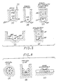
- FIGS. 1A-1E show cross-sections of various exemplary troughline configurations.
- FIG. 1A shows a troughline comprising a troughline conductor 20 supported in air within a conductive through structure 22 having a flat bottom surface 22A and upright sides 22B and 22C.
- FIG. 1B shows a troughline comprising a troughline conductor 25 supported in air within a conductive troughline structure having a radial bottom 27.
- FIG. 1C shows the same troughline as in FIG. 1B, except that the open region within the trough structure is filled with a dielectric material 28 of dielectric constant E r to provide dielectric loading.
- FIG. 1D shows a troughline configuration wherein the troughline conductor 30 is supported in air above the bottom of the troughline structure which comprises a radiused portion 32A and flat portions 32B.
- FIG. 1E shows a troughline configuration like that of FIG. 1A except that a portion of the open region above the conductor 20 within the trough structure is filled with a dielectric material 21 having a dielectric constant E r to provide dielectric loading.
- Troughline is chosen in accordance with the invention to act as an intermediary between the coaxial line and the microstripline because its field configuration shows similarities to both transmission lines, as illustrated in FIGS 2A-2C.
- FIG. 2A illustrates a cross-section of a coaxial transmission line and its electromagnetic field configuration.
- FIG. 2B illustrates a cross-section of a troughline configuration (similar to that of FIG. 1A) and its electromagnetic field configuration.
- FIG. 2C illustrates a cross-section of an open microstrip and its electromagnetic field configuration.
- using troughline helps to realize a well matched transition from the coaxial line onto microstripline.
- the center conductor of the troughline can bend at right angles with no mismatch. Dielectrically loading the troughline prevents higher order waveguide modes (than the TEM mode) from radiating out of the trough.
- the open structure of the troughline allows easy access for assemblying, testing and tuning a microwave integrated circuit (MIC) without the presence of the top cover of the MIC package.
- MIC microwave integrated circuit
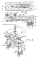
- FIGS. 3 and 4 disclose an exemplary planar microstripline circuit package 100 employing a top cover orthogonal launcher 120 and a bottom plane orthogonal launcher 140 in accordance with the invention.
- the circuit package 100 includes a removable top cover 102, a bottom ground plane 104, and a microstrip transmission circuit 106 generally comprising microstrip conductor 108 and microstrip substrate 110.
- An open channel 150 is machined or molded into the conductive ground plane structure 104, and accepts the microstrip substrate 110 and conductor 108 as shown in FIG. 3.
- An air dielectric region 150 is defined between the upper surface of the substrate 110 and the top cover 102.
- One end 104A of the ground plane structure 104 defines the trough 130 of the top cover launcher 120, and defines an upwardly facing circular opening for receiving a coaxial feedthrough 122.
- the other end 104B of the ground plane structure 104 defines the trough 148 of the ground plane launcher 140, and defines a downwardly facing circular opening 152 for receiving the coaxial feedthrough 142.
- the top cover launcher 120 employs the coaxial feedthrough 122 whose center pin 126 is bent at a right angle to form the trough line center conductor.
- the trough line conductor 126B is mounted in the trough line channel 130, and is connected (via solder connection) to the conductor strip 108 of the microstrip circuit 106.
- a plug 128 of a high dielectric material is fitted into the channel 128 to capacitively load the troughline, thereby preventing higher order modes from propagating out of the trough 130 into the air dielectric region 150.
- the troughline for the top cover launcher is of the configuration shown in FIG. 1(c).
- a coaxial connection can be made to the launcher 120 by a coaxial-to-coaxial connector (not shown) fastened to the top cover 120 via threaded openings 103, or via a screw-in coaxial connector (not shown), or by other conventional means.
- the bottom ground plane orthogonal launcher 140 comprises a coaxial feedthrough device comprising dielectric element 142 and pin 144.
- the coaxial feedthrough device first transitions between the air dielectric coaxial line generally indicated by reference numeral 146, then into a capacitively loaded troughline of the configuration shown in FIG. 1(d), and subsequently into the microstrip line 106.
- the end 144B of the center conductor 144 is bent to form the troughline conductor, and is electrically connected to the microstripline conductor 108 (via a solder connection).
- a separate dielectric plug (similar to plug 128) is not required for the bottom plate launcher, since the trough conductor extends upwardly from the bottom plate, and does not extend significantly into the air dielectric region 150.
- the orthogonal coaxial-to-microstrip launchers described above allow the microwave circuit designer additional flexibility in the design of compact MIC packages operating, for example, at X-band.
- the launchers can be designed to have a maximum VSWR, for example, of 1.10:1 when measured from 6 GHz to 12 GHz. Moreover, the launchers are readily accessible for assembly or RF tuning.
- FIG. 5 is an exploded perspective view showing how the orthogonal coaxial to microstripline launchers are assembled into an exemplary four-way power divider circuit 200 used for active arrays.
- the input signal is provided via coaxial OSP plug connector device 210, and is divided into four signals which are output from the device 200 via the respective coaxial OSP connector jacks 220, 230, 240 and 250.
- the OSP plug 210 may comprise, for example, a type 55575328-02 marketed by Omni Spectra, 21 Continental Boulevard., Merrimack, New Hampshire 03054.
- the OSP jacks may comprise, for example, a type 45585328-02 connector jack marketed by Omni Spectra.
- coaxial connectors mate to coaxial line structures which comprise a dielectric feedthrough seal element (elements 212, 222, 242 and 252 are visible in FIG. 5) and a center conductor (conductors 214, 224, 244 and 254 are visible in FIG. 5).
- the center conductor 214 is bent at right angles to form the troughline conductor for the top cover launcher.
- the top cover launcher includes a dielectric plug 215.
- Pieces 226, 246 and 256 of copper wire are joined at right angles to the tips of the conductors 224, 234, 244, and 254 to from the troughline conductors for the bottom cover launchers.
- the circuit 200 further comprise a microstripline circuit 260 comprising the dielectric substrate 262, conductor strips 264, 266, 268, 270, 272, 274, 276, and 100 ohm chip resistor elements 278, 280 and 282.
- Resistor 278 connects conductor strips 264, 266 and 268.
- Resistor 280 connects conductor strips 268, 270 and 272.
- Resistor 282 connects conductor strips 272, 274 and 276.
- the microstripline divider circuit 250 is itself well known in the art.
- the circuit 200 further comprises a conductive housing 290 and top plate 292.
- a channel 294 is defined in the housing 290 in the configuration of the microstripline substrate 252 so that the substrate 252 may be received within the channel 294.
Landscapes
- Waveguide Aerials (AREA)
- Waveguides (AREA)
- Cable Transmission Systems, Equalization Of Radio And Reduction Of Echo (AREA)
Applications Claiming Priority (2)
| Application Number | Priority Date | Filing Date | Title |
|---|---|---|---|
| US07/415,003 US5416453A (en) | 1989-09-29 | 1989-09-29 | Coaxial-to-microstrip orthogonal launchers having troughline convertors |
| US415003 | 1989-09-29 |
Publications (2)
| Publication Number | Publication Date |
|---|---|
| EP0420241A2 true EP0420241A2 (de) | 1991-04-03 |
| EP0420241A3 EP0420241A3 (en) | 1991-07-31 |
Family
ID=23643950
Family Applications (1)
| Application Number | Title | Priority Date | Filing Date |
|---|---|---|---|
| EP19900118571 Ceased EP0420241A3 (en) | 1989-09-29 | 1990-09-27 | Coaxial-to-microstrip ortjogonal launchers |
Country Status (7)
| Country | Link |
|---|---|
| US (1) | US5416453A (de) |
| EP (1) | EP0420241A3 (de) |
| JP (1) | JPH03124106A (de) |
| KR (1) | KR930008831B1 (de) |
| AU (1) | AU614239B2 (de) |
| CA (1) | CA2025611C (de) |
| IL (1) | IL95733A (de) |
Cited By (2)
| Publication number | Priority date | Publication date | Assignee | Title |
|---|---|---|---|---|
| WO2008036029A1 (en) | 2006-09-22 | 2008-03-27 | Powerwave Technologies Sweden Ab | Method of manufacturing a transverse electric magnetic (tem) mode transmission line and such transmission line |
| GB2471012A (en) * | 2009-06-09 | 2010-12-15 | Secr Defence | Compact ultra wideband antenna and feed arrangement |
Families Citing this family (11)
| Publication number | Priority date | Publication date | Assignee | Title |
|---|---|---|---|---|
| CA2081386A1 (en) * | 1991-10-31 | 1993-05-01 | Clinton O. Holter | Coaxial to microstrip transition |
| CA2147410A1 (en) * | 1995-04-20 | 1996-10-21 | Robert L. Romerein | Circuitry for use with coaxial cable distribution networks |
| CA2160854A1 (en) * | 1995-10-18 | 1997-04-19 | Robert L. Romerein | Top exit coupler |
| US5633615A (en) * | 1995-12-26 | 1997-05-27 | Hughes Electronics | Vertical right angle solderless interconnects from suspended stripline to three-wire lines on MIC substrates |
| USD402293S (en) | 1996-11-27 | 1998-12-08 | Uro Denshi Kogyo Kabushiki Kaisha | CATV power passing tap |
| USD399846S (en) | 1997-06-04 | 1998-10-20 | PCI Technologies Inc. | In-line 8-way splitter/combiner |
| US6827608B2 (en) | 2002-08-22 | 2004-12-07 | Corning Gilbert Inc. | High frequency, blind mate, coaxial interconnect |
| US6992629B2 (en) * | 2003-09-03 | 2006-01-31 | Raytheon Company | Embedded RF vertical interconnect for flexible conformal antenna |
| WO2006138301A2 (en) * | 2005-06-13 | 2006-12-28 | Gale Robert D | Electronic signal splitters |
| US7375533B2 (en) * | 2005-06-15 | 2008-05-20 | Gale Robert D | Continuity tester adaptors |
| US8102326B2 (en) * | 2008-09-12 | 2012-01-24 | Spx Corporation | Broadcast antenna ellipticity control apparatus and method |
Family Cites Families (14)
| Publication number | Priority date | Publication date | Assignee | Title |
|---|---|---|---|---|
| US2895110A (en) * | 1956-08-16 | 1959-07-14 | Varian Associates San Carlos | High frequency apparatus |
| DE1291807B (de) * | 1965-09-30 | 1969-04-03 | Siemens Ag | Mikrowellenbauteil mit wenigstens einem Doppelleitungsabschnitt |
| GB1537407A (en) * | 1976-11-13 | 1978-12-29 | Marconi Instruments Ltd | Micro-circuit arrangements |
| JPS5585103A (en) * | 1978-12-21 | 1980-06-26 | Fujitsu Ltd | Package construction of microwave ic |
| US4280112A (en) * | 1979-02-21 | 1981-07-21 | Eisenhart Robert L | Electrical coupler |
| JPS5691503A (en) * | 1979-12-26 | 1981-07-24 | Nec Corp | Coaxial microstrip converter |
| US4346355A (en) * | 1980-11-17 | 1982-08-24 | Raytheon Company | Radio frequency energy launcher |
| JPS6113583A (ja) * | 1984-06-27 | 1986-01-21 | 日本電気株式会社 | 高周波コネクタ |
| JPS61174801A (ja) * | 1985-01-29 | 1986-08-06 | Maspro Denkoh Corp | 高周波電子機器 |
| US4631505A (en) * | 1985-05-03 | 1986-12-23 | The United States Of America As Represented By The Secretary Of The Navy | Right angle microwave stripline circuit connector |
| US4951011A (en) * | 1986-07-24 | 1990-08-21 | Harris Corporation | Impedance matched plug-in package for high speed microwave integrated circuits |
| US4810981A (en) * | 1987-06-04 | 1989-03-07 | General Microwave Corporation | Assembly of microwave components |
| DE3724945A1 (de) * | 1987-07-28 | 1989-02-09 | Messerschmitt Boelkow Blohm | Uebergang von einer koaxialleitung auf einen achsparallelen hohlleiter |
| US4855697A (en) * | 1988-06-27 | 1989-08-08 | Cascade Microtech, Inc. | Coaxial transmission line to microstrip transmission line launcher |
-
1989
- 1989-09-29 US US07/415,003 patent/US5416453A/en not_active Expired - Lifetime
-
1990
- 1990-09-18 CA CA002025611A patent/CA2025611C/en not_active Expired - Fee Related
- 1990-09-19 IL IL9573390A patent/IL95733A/en not_active IP Right Cessation
- 1990-09-26 AU AU63249/90A patent/AU614239B2/en not_active Ceased
- 1990-09-27 EP EP19900118571 patent/EP0420241A3/en not_active Ceased
- 1990-09-28 JP JP2260354A patent/JPH03124106A/ja active Pending
- 1990-09-28 KR KR1019900015600A patent/KR930008831B1/ko not_active Expired - Fee Related
Cited By (3)
| Publication number | Priority date | Publication date | Assignee | Title |
|---|---|---|---|---|
| WO2008036029A1 (en) | 2006-09-22 | 2008-03-27 | Powerwave Technologies Sweden Ab | Method of manufacturing a transverse electric magnetic (tem) mode transmission line and such transmission line |
| GB2471012A (en) * | 2009-06-09 | 2010-12-15 | Secr Defence | Compact ultra wideband antenna and feed arrangement |
| GB2471012B (en) * | 2009-06-09 | 2013-02-20 | Secr Defence | A compact ultra wideband antenna for transmission and reception of radio waves |
Also Published As
| Publication number | Publication date |
|---|---|
| CA2025611A1 (en) | 1991-03-30 |
| KR930008831B1 (ko) | 1993-09-15 |
| IL95733A (en) | 1994-05-30 |
| JPH03124106A (ja) | 1991-05-27 |
| AU614239B2 (en) | 1991-08-22 |
| US5416453A (en) | 1995-05-16 |
| KR910007173A (ko) | 1991-04-30 |
| IL95733A0 (en) | 1991-06-30 |
| AU6324990A (en) | 1991-04-26 |
| EP0420241A3 (en) | 1991-07-31 |
| CA2025611C (en) | 1994-10-25 |
Similar Documents
| Publication | Publication Date | Title |
|---|---|---|
| US4957456A (en) | Self-aligning RF push-on connector | |
| US11121475B2 (en) | Phased array antenna | |
| US6850128B2 (en) | Electromagnetic coupling | |
| EP0901181B1 (de) | Vertikale Erreger für einen Mikrostreifen-Koaxialübergang mittels leitender kompressibler und lötfreier Verbindungen | |
| EP0985243B1 (de) | Vorrichtung zur mikrowellenübertragung | |
| US6512431B2 (en) | Millimeterwave module compact interconnect | |
| US5689216A (en) | Direct three-wire to stripline connection | |
| US5633615A (en) | Vertical right angle solderless interconnects from suspended stripline to three-wire lines on MIC substrates | |
| US5416453A (en) | Coaxial-to-microstrip orthogonal launchers having troughline convertors | |
| US4768004A (en) | Electrical circuit interconnect system | |
| KR100418452B1 (ko) | 고주파 신호 스위칭 유닛 | |
| US8152534B1 (en) | Connector used for connecting a coaxial cable and a microstrip | |
| US4867704A (en) | Fixture for coupling coaxial connectors to stripline circuits | |
| US5726664A (en) | End launched microstrip or stripline to waveguide transition with cavity backed slot fed by T-shaped microstrip line or stripline usable in a missile | |
| US5724049A (en) | End launched microstrip or stripline to waveguide transition with cavity backed slot fed by offset microstrip line usable in a missile | |
| JP2004513474A (ja) | 超小型、高速、同軸ピン相互接続システム | |
| US6759987B2 (en) | Device for the transmission and /or reception of radar beams | |
| US4906957A (en) | Electrical circuit interconnect system | |
| US5356298A (en) | Wideband solderless right-angle RF interconnect | |
| US6400241B1 (en) | Microwave circuit module and a device for connecting it to another module | |
| US5194875A (en) | Notch radiator elements | |
| US6621386B2 (en) | Apparatus for connecting transmissions paths | |
| US3480887A (en) | System of enclosures and connectors for microwave circuits | |
| JP4211240B2 (ja) | 高周波信号切換装置 | |
| KR20210050276A (ko) | 공진 회로를 구비한 비가역 소자 |
Legal Events
| Date | Code | Title | Description |
|---|---|---|---|
| PUAI | Public reference made under article 153(3) epc to a published international application that has entered the european phase |
Free format text: ORIGINAL CODE: 0009012 |
|
| AK | Designated contracting states |
Kind code of ref document: A2 Designated state(s): CH DE ES FR GB IT LI SE |
|
| PUAL | Search report despatched |
Free format text: ORIGINAL CODE: 0009013 |
|
| AK | Designated contracting states |
Kind code of ref document: A3 Designated state(s): CH DE ES FR GB IT LI SE |
|
| 17P | Request for examination filed |
Effective date: 19920124 |
|
| 17Q | First examination report despatched |
Effective date: 19940124 |
|
| STAA | Information on the status of an ep patent application or granted ep patent |
Free format text: STATUS: THE APPLICATION HAS BEEN REFUSED |
|
| 18R | Application refused |
Effective date: 19951020 |