EP0420262B1 - Bohr-Einsatzstück mit mehrteiliger Schneidstruktur - Google Patents
Bohr-Einsatzstück mit mehrteiliger Schneidstruktur Download PDFInfo
- Publication number
- EP0420262B1 EP0420262B1 EP90118661A EP90118661A EP0420262B1 EP 0420262 B1 EP0420262 B1 EP 0420262B1 EP 90118661 A EP90118661 A EP 90118661A EP 90118661 A EP90118661 A EP 90118661A EP 0420262 B1 EP0420262 B1 EP 0420262B1
- Authority
- EP
- European Patent Office
- Prior art keywords
- bit
- elements
- cutting
- row
- face
- Prior art date
- Legal status (The legal status is an assumption and is not a legal conclusion. Google has not performed a legal analysis and makes no representation as to the accuracy of the status listed.)
- Expired - Lifetime
Links
- 230000015572 biosynthetic process Effects 0.000 claims description 18
- 239000000463 material Substances 0.000 claims description 4
- 238000013270 controlled release Methods 0.000 claims 1
- 230000000149 penetrating effect Effects 0.000 claims 1
- 230000035515 penetration Effects 0.000 claims 1
- 239000011159 matrix material Substances 0.000 description 6
- 239000010432 diamond Substances 0.000 description 4
- UONOETXJSWQNOL-UHFFFAOYSA-N tungsten carbide Chemical compound [W+]#[C-] UONOETXJSWQNOL-UHFFFAOYSA-N 0.000 description 4
- 229910003460 diamond Inorganic materials 0.000 description 3
- 230000003628 erosive effect Effects 0.000 description 3
- 229910052751 metal Inorganic materials 0.000 description 3
- 239000002184 metal Substances 0.000 description 3
- 238000012986 modification Methods 0.000 description 2
- 230000004048 modification Effects 0.000 description 2
- RYGMFSIKBFXOCR-UHFFFAOYSA-N Copper Chemical compound [Cu] RYGMFSIKBFXOCR-UHFFFAOYSA-N 0.000 description 1
- 229910001208 Crucible steel Inorganic materials 0.000 description 1
- 229910000831 Steel Inorganic materials 0.000 description 1
- 238000007792 addition Methods 0.000 description 1
- 229910045601 alloy Inorganic materials 0.000 description 1
- 239000000956 alloy Substances 0.000 description 1
- 239000011230 binding agent Substances 0.000 description 1
- 238000005219 brazing Methods 0.000 description 1
- 230000015556 catabolic process Effects 0.000 description 1
- 239000004927 clay Substances 0.000 description 1
- 239000012141 concentrate Substances 0.000 description 1
- 229910052802 copper Inorganic materials 0.000 description 1
- 239000010949 copper Substances 0.000 description 1
- 238000006731 degradation reaction Methods 0.000 description 1
- 238000012217 deletion Methods 0.000 description 1
- 230000037430 deletion Effects 0.000 description 1
- 238000005553 drilling Methods 0.000 description 1
- 238000005516 engineering process Methods 0.000 description 1
- 230000008595 infiltration Effects 0.000 description 1
- 238000001764 infiltration Methods 0.000 description 1
- 229910001092 metal group alloy Inorganic materials 0.000 description 1
- 239000000843 powder Substances 0.000 description 1
- 239000011347 resin Substances 0.000 description 1
- 229920005989 resin Polymers 0.000 description 1
- 239000004576 sand Substances 0.000 description 1
- 238000007790 scraping Methods 0.000 description 1
- 238000010008 shearing Methods 0.000 description 1
- 239000010959 steel Substances 0.000 description 1
- 239000000758 substrate Substances 0.000 description 1
- 239000011800 void material Substances 0.000 description 1
Images


Classifications
-
- E—FIXED CONSTRUCTIONS
- E21—EARTH OR ROCK DRILLING; MINING
- E21B—EARTH OR ROCK DRILLING; OBTAINING OIL, GAS, WATER, SOLUBLE OR MELTABLE MATERIALS OR A SLURRY OF MINERALS FROM WELLS
- E21B10/00—Drill bits
- E21B10/46—Drill bits characterised by wear resisting parts, e.g. diamond inserts
- E21B10/56—Button-type inserts
- E21B10/567—Button-type inserts with preformed cutting elements mounted on a distinct support, e.g. polycrystalline inserts
Definitions
- the present invention pertains to a rotary drag bit of the kind referred to in the preamble of claim 1. (cf. EP-A-0 264 674)
- planar cutters currently in use are generally formed of a planar layer polycrystalline diamond on a supporting substrate and are commonly called “PDC's", while the kerfing type of cutters are self-supporting thermally stable polycrystalline diamond structures ("TSP's") in the shape of a disc or polyhedron.
- the former type of cutter must be affixed, as by brazing, to a tungsten carbide matrix type of drill bit after the bit is furnaced, since the PDC's are extremely degraded if not totally destroyed by the bit furnacing temperature employed.
- the latter type of cutter, TSP's are so-called because they can survive the bit furnacing operation without degradation.
- TSP cutters One problem confronting PDC cutters, individual TSP cutters, mosaic-type TSP cutters and the newly-introduced large planar TSP cutters, is the dulling of the cutters as the drill bit wears during drilling, causing the bit weight to be applied to an ever-increasing cutter area as the PDC or large TSP cutters flatten and the pointed TSP cutter points wear.
- the TSP "mosaic" planar array cutters suffer the same dulling problems as the PDC's.
- EP-A 0264 674 disclosing impact-fracture inducement means in the shape of reduced-depth matrix between adjacent TSPCD elements of a cutter which provides controlled weaknes planes in the cutter structure thereby providing for fracture of the cutter along predetermined planes of fracture. In this way as the loading on a cutter region increases, the cutter is broken out of the support to provide a new cutter element.
- the invention is a drag bit as claimed in claim 1. Further embodiments are claimed in claims 2 to 14.
- the cutting structure of the present invention will thus wear or dull only to a certain degree or level before the points of the next-lower row of TSP elements will begin to contact the formation.
- the top row elements will break away from the cutting structure, leaving the next row of sharply pointed elements of the cutter array to engage the formation, substantially concentrating the load of the weight on bit on the small area of the points engaging the formation instead of the larger area of the worn top row of elements or, as in the prior art PDC cutters, the flattened cutter tops.
- each row of elements in the array will break off of the array as they wear to a certain degree to permit the points of the next row of elements to engage the formation.
- Drill bit 10 includes a body section 12 which includes cutting structures indicated generally at 14, and gage pads, indicated generally at 16.
- Cutting structures 14 of this embodiment each constitute a single cutting blade in accordance with the present invention.
- Gage pads 16 do not normally serve a cutting function, except insofar as to maintain the gage (diameter) of the hole being bored by bit 10.
- Bit body 12 is preferably at least partially a molded component fabricated through conventional metal infiltration technology, wherein a tungsten carbide powder is infiltrated with a copper-based alloy binder in a mold at elevated temperatures.
- the cutting structure of the present invention is not limited to matrix type infiltrated bits, as it also has utility and may be employed with a hard-faced cast steel body bit, the cutting structure of the present invention being formed on studs or other carrier members secured to the bit. Regardless of whether a cast-matrix or steel body bit is fabricated, a threaded shank 18 extends from the bottom of bit body 12 for securing bit 10 to a drill string.
- Each cutting structure 14 of the embodiment of drill bit 10 extends from proximate the center line 24 of bit 10 to gage 16.
- Each blade-like structure 14 is a mosaic-like array formed of a plurality of polyhedron-shaped thermally stable polycrystalline diamond product (TSP) elements 20 bonded into the tungsten carbide matrix of the bit body 12.
- TSP thermally stable polycrystalline diamond product
- each TSP element has been coated, such as with a metal or metal alloy to facilitate bonding of the material to the matrix.
- each cutting structure 14 includes a generally planar cutting face 22 in which is embedded a plurality of the aforementioned TSP elements 20 with an exposed planar triangular face coplanar with the cutting face.
- Each TSP element 20 is rotationally oriented so that an apex 24 thereof is pointed away from the face 26 of bit body 12, and consequently toward the formation to be cut when the bit is employed at the end of a drill string.
- the TSP elements 20 of this embodiment are aligned in offset rows 28, the TSP elements 20 of each row 28 being spaced apart a sufficient distance to permit the apices 24 of the TSP elements 20 next lower row 28 to extend upwardly therebetween.
- the degree of spacing and the protrusion of the apices 24 of each row 28 into the next higher row 28 is a matter of design choice.
- each row 28 vertically protrudes one-half of the height of a TSP element into the next row 28.
- the TSP elements 20 of the outermost row 28 will engage a formation as the bit is rotated, and apices 24 of TSP elements 20 will cut the formation with a kerfing of plowing action. This will continue until the apices 24 are worn down and dulled, whereupon the apices 24 of the TSP elements 20 of next lower row 28 will begin to engage the formation, again substantially concentrating the weight on the rotating bit on a much smaller area to aggressively cut the formation instead of the bit "riding" on the formation as the element points dull.
- each row 28 of TSP elements 20 dulls during cutting, it is desirable that they break away or are otherwise removed from the bit so as to concentrate the bit load totally on the newly-exposed sharp apices 24 of the next lower row 28 engaging the formation, so that only one row 28 of elements 20 is in substantial cutting engagement with the formation at any given time.
- each TSP element 20 may include a vertical groove 42 therein extending from the base 44 of the element to a point near the geometric center of the element.
- the element groove will induce fracture from impact with the formation and break off from the bit.
- voids or an element of readily erodable material 46 may be placed in the cutting structure behind each element as shown in FIG. 6, the exposure of a void or erodable material as an element 20 wears, resulting in rapid erosion and loss of impact support for the element and subsequent loss thereof.
- Clay or resin-coated sand may be molded to an appropriate shape to provide the erodable element. Hollow metal spheres or other shapes may be used to create voids during the furnacing of the bit.
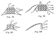
- FIGS. 7A and 7B depict aligned rows of TSP elements 20, wherein each row 28 replaces the one above it as the rows wear and the elements 20 break off.
- the use of fracturable elements or erosion-induced loss, as described with respect to FIGS. 5 and 6, may be employed with the arrangement of FIGS. 7, or, as shown in FIG. 7B, the elements 20 may protrude from the cutting face 22 so as to facilitate erosion-induced loss.
- the elements 20 of uppermost row 28 are shown to protrude more than those in row 28', which in turn protrudes more from cutting face 22 than the elements 20 in lowermost row 28'.
- the difference in degree of protrusion facilitates sequential, row-by-row loss of elements 20.
- arcuate rows 28 as shown in FIGS. 8A and 8B, may be utilized, particularly for smaller cutting structures 14 comprised of few elements 20.
- FIGS. 9-11 the present invention is not limited to triangular TSP elements.
- FIG. 9 illustrates the use of offset rows 28 of small TSP elements 20 in a disc shape.
- FIG. 10 shows rows 28 of square TSP elements 20 rotated to provide apices 24 to engage the formation.
- FIG. 13 illustrates the usage of small octagonal TSP elements 20 in offset rows 28.
- TSP elements 20 may either be closely packed in an interlocking arrangement as shown, or spaced apart.
- any of the TSP element shapes of FIGS. 9-11 may be employed in the arrangement shown in FIG. 7, as will be evident to those of skill in the art.
- FIGS. 12A and 12B illustrate cutting structure 14 of the present invention as embodied in a stud-type carrier 140 such as might be secured to a steel-body bit.
- Carrier 140 includes a cutting element support 142, commonly formed of tungsten carbide, with an integral stud 144 extending from the bottom. Stud 144 may be cylindrical or of other shape to facilitate cutter alignment when inserted in a hole bored in the face of a steel-body bit.
- TSP elements rectangular or non-equilateral triangular TSP elements might be employed in the present invention and more than one shape of TSP element may be used in an array of a cutting structure.
Landscapes
- Engineering & Computer Science (AREA)
- Life Sciences & Earth Sciences (AREA)
- Mining & Mineral Resources (AREA)
- Geology (AREA)
- Mechanical Engineering (AREA)
- Physics & Mathematics (AREA)
- Environmental & Geological Engineering (AREA)
- Fluid Mechanics (AREA)
- Chemical & Material Sciences (AREA)
- Crystallography & Structural Chemistry (AREA)
- General Life Sciences & Earth Sciences (AREA)
- Geochemistry & Mineralogy (AREA)
- Earth Drilling (AREA)
- Excavating Of Shafts Or Tunnels (AREA)
Claims (14)
- Drehbarer Bohrmeißel (10) zur Durchdringung einer unterirdischen Formation, mit einem Meißelschaft (18) zur Befestigung des Bohrmeißels an einem Bohrstrang, einem Meißelkörper (12), der auf dem Meißelschaft (18) angebracht ist und eine Fläche (26) für einen Berührungseingriff mit der Formation aufweist, zumindest einer Schneideinrichtung (20), die auf der Meißelfläche (26) angebracht ist und eine Mehrzahl von Schneidelementen (20) trägt, die in einer eine Mehrzahl von Reihen (28) umfassenden Anordnung vorgesehen sind, wobei jede der Reihen (28) in einem anderen Abstand zur Meißelfläche als zumindest eine andere Reihe (28) angeordnet ist, so daß nur eine Reihe (28) von Elementen (20) zur gleichen Zeit während der Durchdringung der Formation in wesentlichem Schneideingriff mit der Formation steht, und wobei die Schneideinrichtung (14) ferner auf Verschleiß ansprechende, bei Stoßbelastung ein Brechen von Schneidelementen begünstigende Mittel (42,46) umfaßt, dadurch gekennzeichnet , daß die ein Brechen bei Stoßbelastung begünstigenden Mittel (42,46) auf der Rückseite von zumindest einigen der Schneidelemente (20) angeordnet sind und auf Verschleiß der ihnen zugeordneten Schneidelemente (20) für ein kontrolliertes Auslösen dieser Schneidelemente aus der Anordnung ansprechen.
- Bohrmeißel nach Anspruch 1, bei dem die ein Brechen bei Stoßbelastung begünstigenden Mittel von einer Ausnehmung (42) in den der Drehrichtung abgewandten Flächen (40) von zumindest einigen der Schneidelemente (20) gebildet sind.
- Bohrmeißel nach Anspruch 1, bei dem die ein Brechen bei Stoßbelastung begünstigenden Mittel von erodierbarem Material (46) hinter zumindest einigen der Elemente (20) gebildet sind.
- Bohrmeißel nach Anspruch 1, bei dem die ein Brechen bei Stoßbelastung begünstigenden Mittel von Hohlräumen in der Schneideinrichtung (14) hinter zumindest einigen der Elemente (20) gebildet sind.
- Bohrmeißel nach einem der Ansprüche 1 bis 4, bei dem die Elemente (20) von vertikal benachbarten Reihen (28) seitlich versetzt angeordnet sind.
- Bohrmeißel nach Anspruch 5, bei dem die Elemente (20) jeder Reihe (28), die unter sich eine andere Reihe (28) hat, im Abstand zueinander angeordnet sind und Scheitel (24) der Elemente (20) jeder darunter befindlichen Reihe (28) zwischen diese vorspringen.
- Bohrmeißel nach einem der Ansprüche 1 bis 4, bei dem die Reihen (28) im wesentlichen untereinander vertikal fluchtend ausgerichtet sind.
- Bohrmeißel nach einem der Ansprüche 1 bis 7, bei dem die Reihen (28) Vorderseite zu Rückseite in Richtung (30) der Schneidbewegung in Stufenform versetzt sind.
- Bohrmeißel nach Anspruch 8, bei dem die in bezug auf die Fläche (26) des Bohrmeißels (10) oberste Reihe (28) von Elementen (20) die in Richtung (30) der Schneidbewegung vorauseilende Reihe bildet.
- Bohrmeißel nach Anspruch 8, bei dem die in bezug auf die Fläche (26) des Bohrmeißels (10) oberste Reihe (28) von Elementen (20) die in Richtung (30) der Schneidbewegung nachlaufende Reihe bildet.
- Bohrmeißel nach einem der Ansprüche 1 bis 10, bei dem zumindest eine der Reihen (28) nichtlinear verläuft.
- Bohrmeißel nach Anspruch 11, bei dem die nichtlineare Reihe (28) bogenförmig verläuft.
- Bohrmeißel nach einem der Ansprüche 1 bis 12, bei dem die Schneideinrichtung (14) eine im wesentlichen ebene Schneidfläche (22) darbietet und zumindest einige der Reihen (28) von Elementen (20) von der Schneidfläche (22) vorstehen.
- Bohrmeißel nach Anspruch 13, bei dem jede vorstehende Reihe (28) weiter von der Schneidfläche (22) vorsteht als irgendeine dichter an der Meißelfläche (26) gelegene vorstehende Reihe (28).
Applications Claiming Priority (2)
| Application Number | Priority Date | Filing Date | Title |
|---|---|---|---|
| US414703 | 1989-09-29 | ||
| US07/414,703 US5025873A (en) | 1989-09-29 | 1989-09-29 | Self-renewing multi-element cutting structure for rotary drag bit |
Publications (3)
| Publication Number | Publication Date |
|---|---|
| EP0420262A2 EP0420262A2 (de) | 1991-04-03 |
| EP0420262A3 EP0420262A3 (en) | 1992-03-04 |
| EP0420262B1 true EP0420262B1 (de) | 1995-07-12 |
Family
ID=23642588
Family Applications (1)
| Application Number | Title | Priority Date | Filing Date |
|---|---|---|---|
| EP90118661A Expired - Lifetime EP0420262B1 (de) | 1989-09-29 | 1990-09-28 | Bohr-Einsatzstück mit mehrteiliger Schneidstruktur |
Country Status (4)
| Country | Link |
|---|---|
| US (1) | US5025873A (de) |
| EP (1) | EP0420262B1 (de) |
| CA (1) | CA2026498A1 (de) |
| DE (1) | DE69020836T2 (de) |
Families Citing this family (26)
| Publication number | Priority date | Publication date | Assignee | Title |
|---|---|---|---|---|
| US5373900A (en) | 1988-04-15 | 1994-12-20 | Baker Hughes Incorporated | Downhole milling tool |
| US5238074A (en) * | 1992-01-06 | 1993-08-24 | Baker Hughes Incorporated | Mosaic diamond drag bit cutter having a nonuniform wear pattern |
| US5282513A (en) * | 1992-02-04 | 1994-02-01 | Smith International, Inc. | Thermally stable polycrystalline diamond drill bit |
| US5979571A (en) * | 1996-09-27 | 1999-11-09 | Baker Hughes Incorporated | Combination milling tool and drill bit |
| GB9906114D0 (en) | 1999-03-18 | 1999-05-12 | Camco Int Uk Ltd | A method of applying a wear-resistant layer to a surface of a downhole component |
| US6968912B2 (en) * | 2002-12-12 | 2005-11-29 | The Sollami Company | Drill blades for drill bit |
| KR100942983B1 (ko) * | 2007-10-16 | 2010-02-17 | 주식회사 하이닉스반도체 | 반도체 소자 및 그 제조방법 |
| US8127863B2 (en) * | 2007-12-10 | 2012-03-06 | Smith International, Inc. | Drill bit having enhanced stabilization features and method of use thereof |
| US20100089658A1 (en) * | 2008-10-13 | 2010-04-15 | Baker Hughes Incorporated | Drill bit with continuously sharp edge cutting elements |
| US8720609B2 (en) * | 2008-10-13 | 2014-05-13 | Baker Hughes Incorporated | Drill bit with continuously sharp edge cutting elements |
| US20100089661A1 (en) * | 2008-10-13 | 2010-04-15 | Baker Hughes Incorporated | Drill bit with continuously sharp edge cutting elements |
| US8020641B2 (en) * | 2008-10-13 | 2011-09-20 | Baker Hughes Incorporated | Drill bit with continuously sharp edge cutting elements |
| US20100108402A1 (en) * | 2008-10-31 | 2010-05-06 | Baker Hughes Incorporated | Downhole cutting tool and method of making |
| US8887839B2 (en) * | 2009-06-25 | 2014-11-18 | Baker Hughes Incorporated | Drill bit for use in drilling subterranean formations |
| US8757299B2 (en) | 2009-07-08 | 2014-06-24 | Baker Hughes Incorporated | Cutting element and method of forming thereof |
| US8978788B2 (en) | 2009-07-08 | 2015-03-17 | Baker Hughes Incorporated | Cutting element for a drill bit used in drilling subterranean formations |
| EP2479003A3 (de) | 2009-07-27 | 2013-10-02 | Baker Hughes Incorporated | Schleifartikel |
| US8936109B2 (en) | 2010-06-24 | 2015-01-20 | Baker Hughes Incorporated | Cutting elements for cutting tools |
| WO2012006281A2 (en) | 2010-07-06 | 2012-01-12 | Baker Hughes Incorporated | Methods of forming inserts and earth-boring tools |
| US20120199395A1 (en) * | 2011-02-07 | 2012-08-09 | Lynde Gerald D | Cutting elements having a pre-formed fracture plane for use in cutting tools |
| US8778259B2 (en) | 2011-05-25 | 2014-07-15 | Gerhard B. Beckmann | Self-renewing cutting surface, tool and method for making same using powder metallurgy and densification techniques |
| US8807247B2 (en) | 2011-06-21 | 2014-08-19 | Baker Hughes Incorporated | Cutting elements for earth-boring tools, earth-boring tools including such cutting elements, and methods of forming such cutting elements for earth-boring tools |
| US8997897B2 (en) | 2012-06-08 | 2015-04-07 | Varel Europe S.A.S. | Impregnated diamond structure, method of making same, and applications for use of an impregnated diamond structure |
| CN102704853B (zh) * | 2012-06-21 | 2015-07-15 | 四川深远石油钻井工具股份有限公司 | 钻进比压可控的模块切削齿 |
| CN103510859B (zh) * | 2012-06-21 | 2016-01-13 | 四川深远石油钻井工具股份有限公司 | 钻进比压可控的模块切削齿钻头 |
| WO2017106388A1 (en) | 2015-12-14 | 2017-06-22 | Smith International, Inc. | Direct casting of ultrahard insert in bit body |
Family Cites Families (22)
| Publication number | Priority date | Publication date | Assignee | Title |
|---|---|---|---|---|
| US1923488A (en) * | 1931-10-05 | 1933-08-22 | Globe Oil Tools Co | Well bit |
| US2290595A (en) * | 1939-11-01 | 1942-07-21 | L P Kinnear | Rotary drill bit |
| US2966949A (en) * | 1958-07-16 | 1961-01-03 | Jersey Prod Res Co | Full hole permanent drill bit |
| US3140748A (en) * | 1963-05-16 | 1964-07-14 | Kennametal Inc | Earth boring drill bit |
| US3440773A (en) * | 1966-08-26 | 1969-04-29 | Norton Co | Abrasive cutting device |
| FR2135053B1 (de) * | 1971-05-04 | 1974-08-19 | Petroles Cie Francaise | |
| US4150728A (en) * | 1976-11-26 | 1979-04-24 | Smith International, Inc. | Rock drill bit inserts with hollow bases |
| US4073354A (en) * | 1976-11-26 | 1978-02-14 | Christensen, Inc. | Earth-boring drill bits |
| JPS5382601A (en) * | 1976-12-28 | 1978-07-21 | Tokiwa Kogyo Kk | Rotary grinding type excavation drill head |
| US4116289A (en) * | 1977-09-23 | 1978-09-26 | Shell Oil Company | Rotary bit with ridges |
| EP0086086A2 (de) * | 1982-02-05 | 1983-08-17 | Boart International Limited | Schneidvorrichtung, mit einer Schneidvorrichtung versehenes Werkzeug, und Verfahren zum Herstellen einer Schneidvorrichtung |
| US4512426A (en) * | 1983-04-11 | 1985-04-23 | Christensen, Inc. | Rotating bits including a plurality of types of preferential cutting elements |
| US4586574A (en) * | 1983-05-20 | 1986-05-06 | Norton Christensen, Inc. | Cutter configuration for a gage-to-shoulder transition and face pattern |
| US4533004A (en) * | 1984-01-16 | 1985-08-06 | Cdp, Ltd. | Self sharpening drag bit for sub-surface formation drilling |
| US4726718A (en) * | 1984-03-26 | 1988-02-23 | Eastman Christensen Co. | Multi-component cutting element using triangular, rectangular and higher order polyhedral-shaped polycrystalline diamond disks |
| US4606418A (en) * | 1985-07-26 | 1986-08-19 | Reed Tool Company | Cutting means for drag drill bits |
| US4673044A (en) * | 1985-08-02 | 1987-06-16 | Eastman Christensen Co. | Earth boring bit for soft to hard formations |
| US4682663A (en) * | 1986-02-18 | 1987-07-28 | Reed Tool Company | Mounting means for cutting elements in drag type rotary drill bit |
| US4719979A (en) * | 1986-03-24 | 1988-01-19 | Smith International, Inc. | Expendable diamond drag bit |
| GB8612012D0 (en) * | 1986-05-16 | 1986-06-25 | Nl Petroleum Prod | Rotary drill bits |
| GB8709229D0 (en) * | 1987-04-16 | 1987-05-20 | Shell Int Research | Tubular element |
| US4913247A (en) * | 1988-06-09 | 1990-04-03 | Eastman Christensen Company | Drill bit having improved cutter configuration |
-
1989
- 1989-09-29 US US07/414,703 patent/US5025873A/en not_active Expired - Fee Related
-
1990
- 1990-09-28 DE DE69020836T patent/DE69020836T2/de not_active Expired - Fee Related
- 1990-09-28 EP EP90118661A patent/EP0420262B1/de not_active Expired - Lifetime
- 1990-09-28 CA CA002026498A patent/CA2026498A1/en not_active Abandoned
Also Published As
| Publication number | Publication date |
|---|---|
| CA2026498A1 (en) | 1991-03-30 |
| US5025873A (en) | 1991-06-25 |
| EP0420262A3 (en) | 1992-03-04 |
| DE69020836D1 (de) | 1995-08-17 |
| EP0420262A2 (de) | 1991-04-03 |
| DE69020836T2 (de) | 1996-04-04 |
Similar Documents
| Publication | Publication Date | Title |
|---|---|---|
| EP0420262B1 (de) | Bohr-Einsatzstück mit mehrteiliger Schneidstruktur | |
| US6009963A (en) | Superabrasive cutting element with enhanced stiffness, thermal conductivity and cutting efficiency | |
| US6296069B1 (en) | Bladed drill bit with centrally distributed diamond cutters | |
| US7896106B2 (en) | Rotary drag bits having a pilot cutter configuraton and method to pre-fracture subterranean formations therewith | |
| US9359825B2 (en) | Cutting element placement on a fixed cutter drill bit to reduce diamond table fracture | |
| US4586574A (en) | Cutter configuration for a gage-to-shoulder transition and face pattern | |
| US5027912A (en) | Drill bit having improved cutter configuration | |
| EP0246789A2 (de) | Schneidelement für einen Drehbohrmeissel, Drehbohrmeissel mit derartigem Schneidelement und dessen Herstellungsverfahren | |
| US5449048A (en) | Drill bit having chip breaker polycrystalline diamond compact and hard metal insert at gauge surface | |
| US9267333B2 (en) | Impregnated bit with improved cutting structure and blade geometry | |
| EP0418706A1 (de) | Bohrmeissel für weiche bis harte Formationen | |
| EP0155026B1 (de) | Drehbohrmeissel mit Schneidelementen, die mit einer dünnen Schleifstirnschicht ausgerüstet sind | |
| US20040149495A1 (en) | Low-contact area cutting element | |
| US5505273A (en) | Compound diamond cutter | |
| USRE33757E (en) | Diamond drill bit with varied cutting elements | |
| EP0291314A2 (de) | Schneidelement und Drehbohrmeissel mit einem derartigen Element | |
| CA1218353A (en) | Tooth design to avoid shearing stresses | |
| US5099935A (en) | Reinforced rotary drill bit | |
| EP0322347B1 (de) | Fräsmeissel mit Düsen für das Bohren von plastischen Formationen | |
| EP0350045B1 (de) | Bohrmeissel mit Verbundschneidelementen | |
| CA1218355A (en) | Tooth design using cylindrical diamond cutting elements | |
| CA1314866C (en) | Reinforced rotary drill bit | |
| CA1256856A (en) | Earth boring bit for soft to hard formations | |
| NO177439B (no) | Innsats for bruk i borkroner |
Legal Events
| Date | Code | Title | Description |
|---|---|---|---|
| PUAI | Public reference made under article 153(3) epc to a published international application that has entered the european phase |
Free format text: ORIGINAL CODE: 0009012 |
|
| AK | Designated contracting states |
Kind code of ref document: A2 Designated state(s): BE DE FR GB NL |
|
| PUAL | Search report despatched |
Free format text: ORIGINAL CODE: 0009013 |
|
| AK | Designated contracting states |
Kind code of ref document: A3 Designated state(s): BE DE FR GB NL |
|
| 17P | Request for examination filed |
Effective date: 19920827 |
|
| 17Q | First examination report despatched |
Effective date: 19930517 |
|
| GRAA | (expected) grant |
Free format text: ORIGINAL CODE: 0009210 |
|
| AK | Designated contracting states |
Kind code of ref document: B1 Designated state(s): BE DE GB |
|
| REF | Corresponds to: |
Ref document number: 69020836 Country of ref document: DE Date of ref document: 19950817 |
|
| EN | Fr: translation not filed | ||
| PLBE | No opposition filed within time limit |
Free format text: ORIGINAL CODE: 0009261 |
|
| STAA | Information on the status of an ep patent application or granted ep patent |
Free format text: STATUS: NO OPPOSITION FILED WITHIN TIME LIMIT |
|
| 26N | No opposition filed | ||
| PGFP | Annual fee paid to national office [announced via postgrant information from national office to epo] |
Ref country code: DE Payment date: 19990902 Year of fee payment: 10 |
|
| PG25 | Lapsed in a contracting state [announced via postgrant information from national office to epo] |
Ref country code: DE Free format text: LAPSE BECAUSE OF NON-PAYMENT OF DUE FEES Effective date: 20010601 |
|
| REG | Reference to a national code |
Ref country code: GB Ref legal event code: IF02 |
|
| PGFP | Annual fee paid to national office [announced via postgrant information from national office to epo] |
Ref country code: GB Payment date: 20020927 Year of fee payment: 13 Ref country code: BE Payment date: 20020927 Year of fee payment: 13 |
|
| PG25 | Lapsed in a contracting state [announced via postgrant information from national office to epo] |
Ref country code: GB Free format text: LAPSE BECAUSE OF NON-PAYMENT OF DUE FEES Effective date: 20030928 |
|
| PG25 | Lapsed in a contracting state [announced via postgrant information from national office to epo] |
Ref country code: BE Free format text: LAPSE BECAUSE OF NON-PAYMENT OF DUE FEES Effective date: 20030930 |
|
| BERE | Be: lapsed |
Owner name: *BAKER-HUGHES INC. Effective date: 20030930 |
|
| GBPC | Gb: european patent ceased through non-payment of renewal fee |
Effective date: 20030928 |