EP0420286A1 - Appareil pour couvrir un actionneur - Google Patents
Appareil pour couvrir un actionneur Download PDFInfo
- Publication number
- EP0420286A1 EP0420286A1 EP90118744A EP90118744A EP0420286A1 EP 0420286 A1 EP0420286 A1 EP 0420286A1 EP 90118744 A EP90118744 A EP 90118744A EP 90118744 A EP90118744 A EP 90118744A EP 0420286 A1 EP0420286 A1 EP 0420286A1
- Authority
- EP
- European Patent Office
- Prior art keywords
- actuator
- cap apparatus
- communication
- actuator cap
- shaped body
- Prior art date
- Legal status (The legal status is an assumption and is not a legal conclusion. Google has not performed a legal analysis and makes no representation as to the accuracy of the status listed.)
- Granted
Links
- 238000004891 communication Methods 0.000 claims abstract description 43
- 230000006854 communication Effects 0.000 claims abstract description 43
- 239000012530 fluid Substances 0.000 claims abstract description 14
- 239000012298 atmosphere Substances 0.000 claims abstract description 4
- XLYOFNOQVPJJNP-UHFFFAOYSA-N water Substances O XLYOFNOQVPJJNP-UHFFFAOYSA-N 0.000 description 3
- 230000002730 additional effect Effects 0.000 description 1
- 230000006835 compression Effects 0.000 description 1
- 238000007906 compression Methods 0.000 description 1
- 238000012986 modification Methods 0.000 description 1
- 230000004048 modification Effects 0.000 description 1
- 230000029058 respiratory gaseous exchange Effects 0.000 description 1
- 238000004078 waterproofing Methods 0.000 description 1
Images


Classifications
-
- H—ELECTRICITY
- H02—GENERATION; CONVERSION OR DISTRIBUTION OF ELECTRIC POWER
- H02K—DYNAMO-ELECTRIC MACHINES
- H02K5/00—Casings; Enclosures; Supports
- H02K5/04—Casings or enclosures characterised by the shape, form or construction thereof
- H02K5/10—Casings or enclosures characterised by the shape, form or construction thereof with arrangements for protection from ingress, e.g. water or fingers
-
- H—ELECTRICITY
- H02—GENERATION; CONVERSION OR DISTRIBUTION OF ELECTRIC POWER
- H02K—DYNAMO-ELECTRIC MACHINES
- H02K2205/00—Specific aspects not provided for in the other groups of this subclass relating to casings, enclosures, supports
- H02K2205/09—Machines characterised by drain passages or by venting, breathing or pressure compensating means
Definitions
- An actuator cap apparatus is often equipped to an electric motor actuator for water-proofing thereof which is used, for example, in a cruise control system for controlling a throttle valve opening value.
- a conventional type actuator cap apparatus for example , is disclosed in Fig. 8.
- an actuator 100 basically includes a motor case 101 and a motor cap 102.
- An output shaft 103 projecting from the actuator 100 is well known, and the actuator 100 is fixed to a vehicle body BD via bolts 1e (only one is shown).
- the output shaft 103 is operatively connected with a drive unit (not shown) which is accommodated in the motor case 101.
- a seamed portion 104 is formed between the motor case 101 and the motor cap 102.
- An actuator cap apparatus 200 is fitted on the actuator 100 at the motor cap 102 side of the actuator 100.
- the motor case 101 and the motor cap 102 define a space 105 therebetween, and the drive unit is arranged in the space 105.
- a communication hole 106 is formed on the side surface of the motor case 101 for establishing fluid communication between the space 105 and the actuator 100 through a communication pipe 300.
- a communication pipe 300 with a communication conduit 301 is fitted in the communication hole 106.
- an actuator cap apparatus for assuring fluid tightness and the fluid communication between an actuator and the atmosphere, comprising a cup shaped body fluid-tightly mounted on a seamed portion of the actuator having a communication hole, a communication pipe formed integrally with a cup shaped body and positioned away from the communication hole, and an intermediate passage formed in the cup shaped body for assuring fluid communication between the communication hole and the communication pipe.
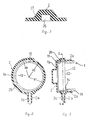
- an actuator cap apparatus 2 is used in an actuator 1.
- Fig. 1 shows a partial cross-sectional view of the actuator 1 and the actuator cap apparatus 2.
- the actuator 1 has a main body 1a (first housing), a cap 1b (second housing) and a drive unit (not shown).
- the drive unit is enclosed in the main body 1a and generates a drive power when a current is supplied.
- the main body 1a is cylindrically shaped and has an opening 1c.
- the cap 1b is formed as a cup-shaped configuration and is fitted on the opening 1c.
- a seamed portion 13 is established between the main body 1a and the cap 1b.
- the side wall of the cap 1b has a communication hole 15 for establishing a communication between an inner portion and an outer portion of the actuator 1.
- the drive unit is accommondated within a space 12 which is defined by the main body 1a and the cap 1b.
- the actuator cap apparatus 2 is fitted on the main body 1a and the cap 1b.
- the actuator cap apparatus 2 has an annular lip 2a and a communication pipe 2b, with a communication conduit 2c.
- An air passage 26 is formed in the inner side wall of the actuator case apparatus 2.
- Fig. 2 represents a cross-sectional view taken along line I-I in Fig. 1.
- the radius R1 of the cap 1b is smaller than the radius R2 of the actuator cap apparatus 2.
- the actuator cap apparatus 2 has different radii, the radius R3 of the air passage portion 26 is larger than the radius R2.
- a concave portion of the actuator cap apparatus 2 is designed to be the air passage 26.
- the communication pipe 2b extends in the downward direction.
- the communication hole 15 of the cap 1b and the communication pipe 2b do not meet each other. The position of the communication hole 15 determines an edge portion of the air passage 26.
- Fig. 4 represents a side view of the actuator cap apparatus 2.
- Fig. 5 represents a plan view of the actuator cap apparatus 2.
- Fig. 7 represents a cross-sectional view taken along line III-III in Fig. 5.
- the actuator cap apparatus 2 has a raised portion 30.
- the raised portion 30 forms an accommodating space 30a, and a part of the cap 1b is enclosed.
- the lip 2a formed at the opening portion of the actuator cap apparatus 2 serves to assure the fluid tightness between the cap 1b and the actuator 1.
- a circumferential length of L1 is longer than that of L2.
- the air passage 26 corresponds to the L1 portion.
- the L2 portion is the wall portion which is fitted on the cap 1b directly.
Landscapes
- Engineering & Computer Science (AREA)
- Power Engineering (AREA)
- Motor Or Generator Frames (AREA)
- General Details Of Gearings (AREA)
- Connection Of Motors, Electrical Generators, Mechanical Devices, And The Like (AREA)
Applications Claiming Priority (2)
| Application Number | Priority Date | Filing Date | Title |
|---|---|---|---|
| JP1989115405U JPH0354342U (fr) | 1989-09-29 | 1989-09-29 | |
| JP115405/89U | 1989-09-29 |
Publications (2)
| Publication Number | Publication Date |
|---|---|
| EP0420286A1 true EP0420286A1 (fr) | 1991-04-03 |
| EP0420286B1 EP0420286B1 (fr) | 1994-11-09 |
Family
ID=14661759
Family Applications (1)
| Application Number | Title | Priority Date | Filing Date |
|---|---|---|---|
| EP90118744A Expired - Lifetime EP0420286B1 (fr) | 1989-09-29 | 1990-09-28 | Appareil pour couvrir un actionneur |
Country Status (4)
| Country | Link |
|---|---|
| US (1) | US5045736A (fr) |
| EP (1) | EP0420286B1 (fr) |
| JP (1) | JPH0354342U (fr) |
| DE (1) | DE69014060T2 (fr) |
Cited By (2)
| Publication number | Priority date | Publication date | Assignee | Title |
|---|---|---|---|---|
| EP0626747A3 (fr) * | 1993-05-24 | 1996-12-11 | Philips Electronics Nv | Moteur électrique à boîtier enveloppé. |
| CN109639020A (zh) * | 2018-11-26 | 2019-04-16 | 孙绍武 | 一种油田抽油机拖动电动机 |
Families Citing this family (12)
| Publication number | Priority date | Publication date | Assignee | Title |
|---|---|---|---|---|
| EP0536441B1 (fr) * | 1991-10-11 | 1993-08-11 | Siemens Aktiengesellschaft | Boîtier de moteur pourvu d'un trou d'écoulement dans sa partie basse |
| EP0705973B1 (fr) * | 1994-10-05 | 1999-04-07 | Denso Corporation | Démarreur muni d'un élément d'étanchement en forme de bande |
| JPH1075546A (ja) * | 1996-08-29 | 1998-03-17 | Sawafuji Electric Co Ltd | 発動発電機における防滴構造 |
| US7180214B1 (en) | 2000-01-10 | 2007-02-20 | General Electric Company | Condenser fan motor dust shield |
| RU2186450C1 (ru) * | 2001-04-27 | 2002-07-27 | Закрытое акционерное общество "ВИНГС-М" | Взрывонепроницаемая оболочка |
| TW525871U (en) * | 2001-11-06 | 2003-03-21 | Lidashi Industry Co Ltd | Improved structure of motor housing |
| RU2279750C2 (ru) * | 2001-11-15 | 2006-07-10 | Николай Андреевич Пелипенко | Способ повышения надежности электрической машины и электрическая машина для его осуществления |
| RU2242075C1 (ru) * | 2003-05-26 | 2004-12-10 | Уфимский государственный авиационный технический университет | Взрывонепроницаемое уплотнение подшипникового узла электродвигателя |
| US7034416B2 (en) * | 2004-01-29 | 2006-04-25 | Siemens Vdo Automotive Inc. | Vented end cap with integrated splash shield for permanent magnet DC motor |
| US8221099B2 (en) * | 2008-03-31 | 2012-07-17 | Honda Motor Co. Ltd. | Windshield washer pump with breather hole cover |
| FR2939245B1 (fr) * | 2008-11-28 | 2011-04-01 | Bernard L | Dispositif de connexion d'un servomoteur a au moins un cable electrique. |
| CN111786494B (zh) * | 2020-06-08 | 2022-11-04 | 珠海格力电器股份有限公司 | 电机及其控制方法、装置、设备和电机系统 |
Citations (1)
| Publication number | Priority date | Publication date | Assignee | Title |
|---|---|---|---|---|
| DE877026C (de) * | 1938-09-21 | 1953-05-18 | Siemens Ag | Gekapselte elektrische Maschine |
Family Cites Families (4)
| Publication number | Priority date | Publication date | Assignee | Title |
|---|---|---|---|---|
| US2500532A (en) * | 1941-07-29 | 1950-03-14 | English Electric Co Ltd | Cooling means for machines |
| US2824984A (en) * | 1956-05-15 | 1958-02-25 | Garrett H Harris | Electric motor housing |
| GB2201047B (en) * | 1987-01-16 | 1990-07-18 | Johnson Electric Ind Mfg | End cap for an electric motor |
| DE3717180A1 (de) * | 1987-05-22 | 1988-12-08 | Licentia Gmbh | Elektromotor mit angebautem tachogenerator |
-
1989
- 1989-09-29 JP JP1989115405U patent/JPH0354342U/ja active Pending
-
1990
- 1990-09-28 US US07/590,703 patent/US5045736A/en not_active Expired - Fee Related
- 1990-09-28 EP EP90118744A patent/EP0420286B1/fr not_active Expired - Lifetime
- 1990-09-28 DE DE69014060T patent/DE69014060T2/de not_active Expired - Fee Related
Patent Citations (1)
| Publication number | Priority date | Publication date | Assignee | Title |
|---|---|---|---|---|
| DE877026C (de) * | 1938-09-21 | 1953-05-18 | Siemens Ag | Gekapselte elektrische Maschine |
Non-Patent Citations (1)
| Title |
|---|
| PATENT ABSTRACTS OF JAPAN vol. 10, no. 347 (E-457)(2403) 21 November 1986, & JP-A-61 147746 (MATSUSHITA) 5 July 1986, * |
Cited By (2)
| Publication number | Priority date | Publication date | Assignee | Title |
|---|---|---|---|---|
| EP0626747A3 (fr) * | 1993-05-24 | 1996-12-11 | Philips Electronics Nv | Moteur électrique à boîtier enveloppé. |
| CN109639020A (zh) * | 2018-11-26 | 2019-04-16 | 孙绍武 | 一种油田抽油机拖动电动机 |
Also Published As
| Publication number | Publication date |
|---|---|
| EP0420286B1 (fr) | 1994-11-09 |
| JPH0354342U (fr) | 1991-05-27 |
| DE69014060D1 (de) | 1994-12-15 |
| US5045736A (en) | 1991-09-03 |
| DE69014060T2 (de) | 1995-03-30 |
Similar Documents
| Publication | Publication Date | Title |
|---|---|---|
| EP0420286B1 (fr) | Appareil pour couvrir un actionneur | |
| KR101628673B1 (ko) | 모터 펌프 조립체 | |
| US4743169A (en) | Diaphragm-type vacuum pump device | |
| EP1158179A1 (fr) | Event pour accumulateur hydraulique et méthode de fabrication | |
| CN111853210B (zh) | 用于商用车的具备带有排气系统的变速器壳体的变速器 | |
| EP1338234B1 (fr) | Moteur de soufflante | |
| JP2009106024A (ja) | ブリーザ装置 | |
| EP0692416A2 (fr) | Dispositif de commande de la pression de fluide de freinage | |
| JPS6336210Y2 (fr) | ||
| KR870002377A (ko) | 자동차용 부압공급장치 | |
| US4491094A (en) | Vacuum pump-radiator fan drive system | |
| CN110061588A (zh) | 驱动电机和变速器的通气构造 | |
| EP0999391A3 (fr) | Soupape de réglage actionnée électriquement | |
| US6637837B2 (en) | Vacuum booster air intake via engine compartment breather passage | |
| EP1045148A3 (fr) | Pompe à carburant pour véhicules avec système de purge à haut rendement | |
| EP0159968A2 (fr) | Pompe pneumatique à palettes avec carter en tôle métallique estampée | |
| WO1990008273A1 (fr) | Joint etanche a l'huile | |
| JPH0828704A (ja) | 自在継手用ブーツ | |
| JPH09195804A (ja) | アクチュエータ装置 | |
| JPH077889A (ja) | ファンモータの防塵構造 | |
| US4807438A (en) | Reservoir inlet assembly for a master cylinder | |
| JP3010441U (ja) | シールの構造 | |
| JPS6242929U (fr) | ||
| KR200235367Y1 (ko) | 자동차변속기용에어브리더 | |
| EP0639713A1 (fr) | Pompe à piston |
Legal Events
| Date | Code | Title | Description |
|---|---|---|---|
| PUAI | Public reference made under article 153(3) epc to a published international application that has entered the european phase |
Free format text: ORIGINAL CODE: 0009012 |
|
| AK | Designated contracting states |
Kind code of ref document: A1 Designated state(s): DE FR GB |
|
| 17P | Request for examination filed |
Effective date: 19910430 |
|
| 17Q | First examination report despatched |
Effective date: 19930920 |
|
| GRAA | (expected) grant |
Free format text: ORIGINAL CODE: 0009210 |
|
| AK | Designated contracting states |
Kind code of ref document: B1 Designated state(s): DE FR GB |
|
| REF | Corresponds to: |
Ref document number: 69014060 Country of ref document: DE Date of ref document: 19941215 |
|
| ET | Fr: translation filed | ||
| PLBE | No opposition filed within time limit |
Free format text: ORIGINAL CODE: 0009261 |
|
| STAA | Information on the status of an ep patent application or granted ep patent |
Free format text: STATUS: NO OPPOSITION FILED WITHIN TIME LIMIT |
|
| PGFP | Annual fee paid to national office [announced via postgrant information from national office to epo] |
Ref country code: FR Payment date: 19950911 Year of fee payment: 6 |
|
| PGFP | Annual fee paid to national office [announced via postgrant information from national office to epo] |
Ref country code: GB Payment date: 19950919 Year of fee payment: 6 |
|
| PGFP | Annual fee paid to national office [announced via postgrant information from national office to epo] |
Ref country code: DE Payment date: 19950928 Year of fee payment: 6 |
|
| 26N | No opposition filed | ||
| PG25 | Lapsed in a contracting state [announced via postgrant information from national office to epo] |
Ref country code: GB Effective date: 19960928 |
|
| PG25 | Lapsed in a contracting state [announced via postgrant information from national office to epo] |
Ref country code: FR Effective date: 19960930 |
|
| GBPC | Gb: european patent ceased through non-payment of renewal fee |
Effective date: 19960928 |
|
| PG25 | Lapsed in a contracting state [announced via postgrant information from national office to epo] |
Ref country code: DE Effective date: 19970603 |
|
| REG | Reference to a national code |
Ref country code: FR Ref legal event code: ST |
|
| REG | Reference to a national code |
Ref country code: FR Ref legal event code: ST |