EP0420334A1 - Moteur pas à pas à angle variable - Google Patents
Moteur pas à pas à angle variable Download PDFInfo
- Publication number
- EP0420334A1 EP0420334A1 EP90202514A EP90202514A EP0420334A1 EP 0420334 A1 EP0420334 A1 EP 0420334A1 EP 90202514 A EP90202514 A EP 90202514A EP 90202514 A EP90202514 A EP 90202514A EP 0420334 A1 EP0420334 A1 EP 0420334A1
- Authority
- EP
- European Patent Office
- Prior art keywords
- rotor
- pole
- north
- stepper motor
- stator
- Prior art date
- Legal status (The legal status is an assumption and is not a legal conclusion. Google has not performed a legal analysis and makes no representation as to the accuracy of the status listed.)
- Ceased
Links
- 238000004804 winding Methods 0.000 claims abstract description 45
- 239000000463 material Substances 0.000 claims description 20
- 230000002093 peripheral effect Effects 0.000 claims description 10
- 230000001939 inductive effect Effects 0.000 claims description 6
- 230000001419 dependent effect Effects 0.000 claims description 5
- 238000002955 isolation Methods 0.000 claims 2
- 238000006073 displacement reaction Methods 0.000 abstract 1
- 239000010960 cold rolled steel Substances 0.000 description 8
- 239000004033 plastic Substances 0.000 description 6
- 229920003023 plastic Polymers 0.000 description 6
- 239000000853 adhesive Substances 0.000 description 5
- 230000001070 adhesive effect Effects 0.000 description 5
- 229910000828 alnico Inorganic materials 0.000 description 5
- 229910000859 α-Fe Inorganic materials 0.000 description 5
- XAGFODPZIPBFFR-UHFFFAOYSA-N aluminium Chemical compound [Al] XAGFODPZIPBFFR-UHFFFAOYSA-N 0.000 description 4
- 229910052782 aluminium Inorganic materials 0.000 description 4
- 239000010935 stainless steel Substances 0.000 description 4
- 229910001220 stainless steel Inorganic materials 0.000 description 4
- 230000000694 effects Effects 0.000 description 3
- 229910000906 Bronze Inorganic materials 0.000 description 2
- 239000004593 Epoxy Substances 0.000 description 2
- 239000004677 Nylon Substances 0.000 description 2
- 230000004323 axial length Effects 0.000 description 2
- 239000010974 bronze Substances 0.000 description 2
- 238000010276 construction Methods 0.000 description 2
- KUNSUQLRTQLHQQ-UHFFFAOYSA-N copper tin Chemical compound [Cu].[Sn] KUNSUQLRTQLHQQ-UHFFFAOYSA-N 0.000 description 2
- 239000012777 electrically insulating material Substances 0.000 description 2
- 239000000696 magnetic material Substances 0.000 description 2
- 229920001778 nylon Polymers 0.000 description 2
- 229920006395 saturated elastomer Polymers 0.000 description 2
- 125000006850 spacer group Chemical group 0.000 description 2
- 238000003466 welding Methods 0.000 description 2
- 238000000926 separation method Methods 0.000 description 1
- 230000001360 synchronised effect Effects 0.000 description 1
Images


Classifications
-
- H—ELECTRICITY
- H02—GENERATION; CONVERSION OR DISTRIBUTION OF ELECTRIC POWER
- H02K—DYNAMO-ELECTRIC MACHINES
- H02K37/00—Motors with rotor rotating step by step and without interrupter or commutator driven by the rotor, e.g. stepping motors
-
- H—ELECTRICITY
- H02—GENERATION; CONVERSION OR DISTRIBUTION OF ELECTRIC POWER
- H02K—DYNAMO-ELECTRIC MACHINES
- H02K37/00—Motors with rotor rotating step by step and without interrupter or commutator driven by the rotor, e.g. stepping motors
- H02K37/10—Motors with rotor rotating step by step and without interrupter or commutator driven by the rotor, e.g. stepping motors of permanent magnet type
Definitions
- This invention relates to a permanent magnet stepper motor, and in particular to such a motor for controllably moving a rotor to variable angle rotational positions.
- a stepper motor is a versatile device having many different uses.
- a stepper motor can be operated as a synchronous motor powered by pulses of electrical current in such applications as clocks, meters, timing devices and recorders.
- Such a motor can also be pulsed at will to effect predetermined increments of movement of elements such as print heads and paper feeders in printers.
- a stepper motor can also be pulsed at variable speeds to drive apparatus such as a pump which must be operated at variable flow rates.
- a typical permanent magnet stepper motor is a one or two phase device comprising a rotor disposed for rotation around a central axis within an annular stator.
- the rotor includes around ifs circumference a permanently magnetized region which successively forms a number of North-South pole pairs.
- the stator includes first and second joined field cups for each phase, each containing a winding of insulated wire surrounding a plurality of magnetizable pole pieces corresponding in number to the magnetic poles in the rotor.
- the pole pieces of the first field cup are angularly displaced from those of the second field cup to effect a rotational force on the rotor when electrical current is passed through the windings.
- the rotor can be controllably stepped through discrete rotational movements. Further details of typical stepper motor structure, operation and drive circuity can be obtained from a publication entiled AIRPAX Stepper Motor Handbook published by Airpax Corporation, 604 West Johnson Avenue, P.0. Box 590, Cheshire, CT, U.S.A. This Handbook is hereby incorporated by reference.
- One limitation of conventional single phase stepper motors is their inability to vary the rotational positions to which the rotor is stepped. Both the direction and the speed of rotation of the rotor are electrically controllable, but the discrete rotational positions to which the rotor can be positioned are fixed by the positions of the stator pole pieces. In some applications, it is desirable to electrically control the angular separation between the positions to which the rotor can be rotated, as well as the speed and direction of rotation. This capability would enable the user to electrically adjust the angle of rotation to match his needs and to change the angle at will. Some examples of such applications are motors for powering scanner mirrors in laser scanner devices and for powering strip chart recorders.
- a variable angle stepper motor comprises a stator, a permanent magnet rotor and bias magnet means.
- the stator defines an orifice having a central axis and includes first and second pole pieces of magnetically permeable material disposed adjacent different sectors of a peripheral region of the orifice.
- An electrically conductive winding is arranged in the stator for inducing magnetic North and South poles in the first and second pole pieces.
- the permanent magnet rotor is mounted for rotation around the axis and has a first portion disposed within the stator orif ice in proximity to the pole pieces and a second portion extending out of the stator orifice.
- the rotor is magnetized such that it has a North pole in a first sector thereof and a South pole in a second sector thereof.
- Each of the poles may have radially extending magnetic field lines.
- the bias magnet means is disposed around the axis adjacent the second portion of the rotor and is magnetized such that it has a North pole in a first sector thereof and a South pole in a second sector thereof. Each of these poles may have axially extending magnetic field lines.
- the variable angle stepper motor further comprises spring magnet means.
- the spring magnet means is mounted for rotation around the axis with the rotor and is magnetized such that it also has a North pole in a first sector thereof and a South pole in a second sector thereof. Each of these poles has axially extending magnetic field lines.
- Both the magnetic field strengths and the angular positions of the North-South poles in the spring and bias magnet means are predetermined to predictably influence the rotational position of the rotor and to make the position dependent on the magnitude of the electric current passing through the winding.
- the magnetic fields produced by the stator, the rotor and the bias magnet each have only one North-South pole pair, and the bias magnet is oriented relative to the stator such that their respective poles are angularly separated by 90 degrees.
- the magnetic fields produced by the stator, the rotor, the spring magnet means and the bias magnet means each have only one North-South pole pair, and the bias magnet means is oriented relative to the stator such that their respective poles are angularly separated by 90 degrees.
- the stator includes first and second cup shaped members of magnetically permeable material each having a central opening substantially coextensive with the orifice.
- the first and second pole pieces are formed by respective arcuate portions of the cup shaped members which are disposed adjacent different sectors of a peripheral region of the orifice.
- the members are dimensioned and fitted together to form an annular space surrounding the pole pieces and to form a magnetic field gap between the pole pieces.
- the stator winding is arranged within the annular space for inducing magnetic North and South poles in the first and second pole pieces, respectively, when an electric current is passed through the winding in a first direction, and for inducing opposite poles in the pole pieces when the current is passed through the winding in the opposite direction.
- variable angle stepper motor By referring to Figures 1, 2 and 3a together, which are drawn substantially to scale, the assembly and construction of a preferred embodiment of the variable angle stepper motor can be readily understood.
- All of the parts of the stepper motor are arranged along and centered on the central axis X-X.
- An outher field cup 10A and an inner field cup 10B disposed within the outer cup collectively form a stator housing at one end of the motor.
- the field cups could be joined at abutting edges, but the arrangement shown in the drawing is simpler to assemble.
- the field cups are stamped or otherwise made from a magnetically permeable material, such as cold rolled steel, and include respective central openings 12A, 12B and respective arcuate portions forming pole pieces 14A, 14B.
- the field cups also include aligned notches, of which only one (16A) is visible in Figure 1. In the assembled stator housing, these notches define an opening for wire leads of a stator winding.
- the pole pieces 14A, 14B each extend through an arc of slightly less than 180 degrees, are in opposite sectors of the illustrated circular cross section, and are separated by gaps 15A, 15B.
- These pole pieces together with peripheral and side walls of the outer and inner field cups, define a substantially closed annular space in which a stator winding 18 is disposed.
- This winding comprises a coil of insulated electrical wire, such as magnet wire, terminating in leads 20A, 20B wound around a bobbin 22 of electrically insulating material such as nylon. These leads extend through the stator housing opening defined by the notches 16A (shown) and 16B (not shown).
- the rotor of the stepper motor comprises an elongate annular part 24 of a permanently magnetized material such as ferrite or alnico, which is affixed to a hub 26 of a nonmagnetic material, such as aluminum, by means of an epoxy 25.
- the hub 26 is affixed to a nonmagnetic stainless steel shaft 28 by means of an adhesive or press fit.
- the permanently magnetized annular part 24 has a single North pole and a single South pole, which are located in diametrically opposite sectors of the previously mentioned circular cross section. As indicated by the arrow passing through part 24, the magnetic field lines at the poles extend radially from the poles.
- the axial length of the annular part 24 is substantially longer than that of the stator housing formed by the field cups 10A, 10B.
- a length L1 of the annular part is contained within an orifice of the stator housing defined by the arcuate pole pieces 14A, 14B of the field cups.
- the remainder of the annular part, having a length L2 extends out of the stator housing and is surrounded by an annular bias magnet 30 which is affixed to an inner surface of the mounting cup 32 by means of an adhesive or a press fit.
- the mounting cup has a peripheral edge which abuts a corresponding edge of the outer field cup 10A and surrounds a peripheral portion of the inner field cup 10B.
- the mounting cup may be manufactured from a magnetic material, such as cold rolled steel, or from a nonmagnetic material, such as aluminum or plastic.
- the bias magnet 30 is formed of a permanently magnetized material, such as ferrite or alnico, and has an inner diameter D1 which is substantially larger than the outer diameter D2 of the annular part 24 (see Figure 3a).
- the bias magnet has a single North pole and a single South pole which are located in diametrically opposite sectors of the illustrated cross section and are disposed adjacent respective ones of the gaps 15A, 15B. As indicated by the arrow passing through the bias magnet, the magnetic field lines at the poles extend radially from the poles.
- the rotor is rotatably mounted in the stepper motor by means of sintered bronze bearings 34, 36 into which opposite ends of the shaft 28 exend.
- Bearing 34 is mounted in a central opening in the mounting cup 32 and bearing 36 is moutned in a central opening in a disc shaped mounting plate 38 of any rigid material.
- the mounting plate is made of cold rolled steel and is affixed to an end surface of the outer field cup 10A by means of staking, spot welding or riveting.
- a plastic spacer 40 and a washer 42 are disposed on the shaft 28 on opposite sides of the hub 26 to axially position the annular part 24 within the motor and to prevent opposite ends of the annular part from rubbing against other parts of the motor.
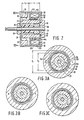
- Figure 2 shows the structural interrelationship of the electromagnetic parts of the motor.
- Figures 3a, 3b, 3c physically illustrate the rotational position of the rotor for three different electromagnetic conditions.
- Figures 4a, 4b, 4c schematically illustrate the operation of a stator winding drive circuit for the three conditions.
- This drive circuit includes four transistors Q1, Q2, Q3, Q4 which are electrically connected to the leads 20A, 20B of the winding.
- transistors Q1, Q4 are biased OFF, transistors Q2, Q3 are biased ON (in a saturated, fully conducting state) and a current I+ passes through the stator winding 18 in the direction indicated by the arrowheads.
- the current I+ passing through the winding induces in the stator field cups a magnetic field having North and South poles in the pole pieces 14A and 14B, respectively.
- the attractive force of the induced poles causes the rotor to rotate to an equilibrium position at an angle + ⁇ where the rotor North pole is disposed at an intermediate position between the stator pole piece 14B and the unchanging South pole of the bias magnet 30.
- This angle can be adjusted to any desired value from near 0 to almost 90 degrees by simply adjusting the magnitude of the current I+. In the illustrated embodiment, this could be done by adjusting the resistance of a variable resistor R which is electrically connected in series with the transistor circuit and a constant source of potential V.
- transistors Q1 and Q4 are biased ON, transistors Q2 and Q3 are biased OFF, and a current I ⁇ passes through the stator winding 18 in the opposite direction, as indicated by the arrowheads.
- the current I ⁇ passing through the winding induces in the stator field cups a magnetic field having North and South poles in the stator pole pieces 14B and 14A, respectively.
- the attractive force of the induced poles causes the rotor to rotate to an equilibrium position at an angle - ⁇ where the rotor North pole is disposed at an intermediate position between the stator pole piece 14A and the unchanging South pole of the bias magnet 30.
- This angle can be adjusted to any desired value from near 0 degrees to almost -90 degrees by simply adjusting the magnitude of the current I ⁇ , again by adjusting the resistance R. This adjustment will also affect the angle + ⁇ , unless an alternative circuit arrangement is utilized which provides separate adjustments for the two currents.
- stepper motor is merely illustrative of one embodiment of the invention, and many alternative forms and variations are possible.
- the drive circuit illustrated in Figure 4 could be replaced with a circuit which selectively passes through the stator winding a plurality of different current magnitudes. By choosing the current magnitudes to correspond to predetermined angular positions, the circuit could be utilized to controllably step the rotor to the positions.
- annular rotor part 24 is replaced with a bar magnet part 24A, as illustrated in Figure 5.
- Part 24A is generally rectangular in cross section, but has two curved diametrically opposed surfaces with radii corresponding to that of the circular outer surface of part 24.
- bar magnet part can be more precisely magnetized in predefined polar sectors.
- a larger number of pole pairs can be provided in an annular part.
- either or both of the annular rotor part 24 and the bias magnet 30 may be provided with a plurality of pole pairs.
- All of the parts of the stepper motor are arranged along and centered on the central axis X′-X′.
- An outer field cup 110A and an inner field cup 110B disposed within the outer cup collectively form a stator housing at one end of the motor.
- the field cups could be joined at abutting edges, but the arrangement shown in the drawing is simpler to assemble.
- the field cups are stamped or otherwise made from magnetically permeable material, such as cold rolled steel, and include respective cental openings 112A, 112B and respective arcuate portions forming pole pieces 114A, 114B.
- the field cups also include aligned notches, of which only one (116A) is visible in Figure 1. In the assembled stator housing, these notches define an opening for wire leads of a stator winding.
- the pole pieces 114A, 114B eache extend through an arc of slightly less than 180 degrees, are in opposite sectors of the illustrated circular cross section, and are separated by gaps 115A, 115B.
- These pole pieces together with peripheral and side walls of the outer and inner field cups, define a substantially closed annular space in which a stator winding 118 is disposed.
- This winding comprises a coil of insulated electrical wire, such as magnet wire, terminating in leads 120A, 120B wound around a bobbin 122 of electrically insulating material such as nylon. These leads extend through the stator housing opening defined by the notches 116A (shown) and 116B (not shown).
- the rotor of the stepper motor comprises an elongate annular part 124 of a permanently magnetized material such as ferrite or alnico, which is affixed to a hub 126 of a rigid material, such as aluminum or cold rolled steel, by means of an epoxy 125.
- the hub 126 is affixed to a nonmagnetic stainless steel shaft 128 by means of an adhesive or press fit.
- the permanently magnetized annular part 124 has a single North pole and a single South pole, which are located in diametrically opposite sectors of the previously mentioned circular cross section. As indicated by the arrow passing through part 124, the magnetic field lines at the poles extend radially from the poles.
- the axial length of the annular part 124 is substantially equal to that of the stator housing formed by the field cups 110A, 110B, and this magnetized part is contained within an orifice of the stator housing defined by the arcuate pole pieces 114A, 114B of the field cups.
- a disc shaped spring magnet 130A of a permanently magnetized material such as ferrite or alnico
- a disc shaped magnetic isolator 131 of a magnetically permeable material such as cold rolled steel.
- this magnet has North and South poles with axially extending magnetic field lines in diametrically opposite sectors.
- the isolator 131 intercepts and returns to its source magnetic field lines originating from the rotor magnet 124 and the spring magnet 130A, thereby effectively isolating each of these magnets from the magnetic field of the other.
- An annular bias magnet 130B is affixed to an inner surface of the mounting cup 132 by means of an adhesive or a press fit.
- the mounting cup has a peripheral edge which abuts a corresponding edge of the outer field cup 110A and surrounds a peripheral portion of the inner field cup 110B.
- the mounting cup may be manufactured from a magnetic material, such as cold rolled steel, or from a nonmagnetic material, such as aluminum or plastics.
- the bias magnet 130B is formed of a permanently magnetized material, such as ferrite or alnico, and is disposed immediately adjacent the spring magnet 130A.
- the bias magnet has a single North pole and a single South pole which are located in diametrically opposite sectors of the magnet and have axially extending field lines as illustrated by the N-S arrows illustrated in Figure 6.
- the magnetic field lines passing through the bias magnet and the spring magnet at their North and South poles are depicted in Figures 8a - 8c by dots and crosses.
- the dots represent magnetic field lines leaving the drawing sheet and the crosses represent mgnetic field lines entering the drawing sheet.
- the North and South poles of the bias magnet 130B are angularly displaced from the gaps 115A, 115B separating the stator pole pieces by approximately ninety degrees.
- the rotor is rotatably mounted in the stepper motor by means of sintered bronze bearings 134, 136 into which opposite ends of the shaft 128 extend.
- Bearing 134 is mounted in a central opening in the mounting cup 132 and bearing 136 is mounted in a central opening in a disc shaped mounting plate 138 of any rigid material.
- the mounting plate is made of cold rolled steel and is affixed to an end surface of the outer field cup 110A by means of staking, spot welding or riveting.
- a plastic spacer 140 and a washer 142 are disposed on the shaft 128 on opposite sides of the hub 126 to axially position the annular part 124 within the motor and to prevent opposite ends of the annular part from rubbing against other parts of the motor.
- Figure 7 shows the structural interrelationship of the electromagnetic parts of the motor.
- Figures 8a, 8b, 8c illustrate the rotational positions of the rotor for three different electromagnetic conditions.
- Figures 9a, 9b, 9c schematically illustrate the operation of a stator winding drive circuit for the three conditions.
- This drive circuit includes four transistors Q1, Q2, 03, Q4 which are electrically connected to the leads 120A, 120B of the winding.
- the spring magnet has rotated to a position where the magnetic field lines produced thereby align with those of the stationary bias magnet, causing the attached rotor to rotate to the indicated position where its North and South poles align with the gaps 115B and 115A, respectively, separating the pole pieces 114A, 114B of the stator opposite polarity South and North poles, respectively, of the bias magnet.
- the transistors Q1, Q4 are biased OFF, transistors Q2, Q3 are biased ON (in a saturated, fully conducting state) and a current I+ passes through the stator winding 118 in the direction indicated by the arrowheads.
- the current I+ passing through the winding induces in the stator field cups a magnetic field having North and South poles in the pole pieces 114A and 114B, respectively.
- the attractive force of the induced poles causes the rotor to rotate in a counter clockwise direction toward a position where its North and South poles would align with the opposite polarity South and North poles induced in the stator pole pieces.
- Magnet 130A acts like a spring and attempts to rotate the attached rotor in a clockwise direction to the position illustrated in Figure 8a, where the polar fields align.
- the rotor comes to rest at an equilibrium position at an angle + ⁇ .
- This angle can be adjusted to any desired value from near 0 degrees to almost +90 degrees by simply adjusting the magnitude of the current I+, thereby adjusting the rotary force imposed on the rotor magnet by the magnetic field induced in the stator pole pieces. In the illustrated embodiment, this could be done by adjusting the resistance of a variable resistor R which is electrically connected in series with the transistor circuit and a constant source of potential V.
- transistors Q1 and Q4 are biased ON, transistors Q2 and Q3 are biased OFF, and a current I ⁇ passesl through the stator winding 118 in the opposite direction, as indicated by the arrowheads.
- the current 1 passing through the winding induces in the stator field cups a magnetic field having North and South poles in the stator pole pieces 114B and 114A, respectively.
- the attractive force of the induced poles causes the rotor to rotate in a clockwise direction toward a position where its poles align with the opposite polarity poles induced in the stator pole pieces.
- attached spring magnet 130A attempts to rotate the rotor in a counter clockwise direction to effect alignment of the spring and bias magnet fields.
- the rotor comes to rest at an equilibrium position at an angle - ⁇ .
- This angle can be adjusted to any desired value from near 0 degrees to almost -90 degrees by simply adjusting the magnitude of the current I ⁇ , again by adjusting the resistance A. This adjustment will also affect the angle + ⁇ , unless an alternative circuit arrangement is utilized which provides separate adjustments for the two currents.
- stepper motor is merely illustrative of one embodiment of the invention, and many alternative forms and variations are possible.
- the drive circuit illustrated in Figure 9 could be replaced with a circuit which selectively passes through the stator winding a plurality of different current magnitudes. By choosing the current magnitudes to correspond to predetermined angular positions, the circuit could be utilized to controllably step the rotor to the positions.
- annular rotor part 124 is replaced with a bar magnet part 124A, as illustrated in Figure 10.
- Part 124A is generally rectangular in cross section, but has two curved diametrically opposed surfaces with radii corresponding to that of the circular outer surface of part 124.
- bar magnet part can be more precisely magnetized in predefined polar sectors.
- a larger number of pole pairs can be provided in an annular part.
- either or both of the annular rotor part 124 and the bias magnet 130B may be provided with a plurality of pole pairs.
Landscapes
- Engineering & Computer Science (AREA)
- Power Engineering (AREA)
- Reciprocating, Oscillating Or Vibrating Motors (AREA)
Applications Claiming Priority (4)
| Application Number | Priority Date | Filing Date | Title |
|---|---|---|---|
| US412702 | 1989-09-26 | ||
| US07/412,702 US4973866A (en) | 1989-09-26 | 1989-09-26 | Variable angle stepper motor |
| US07/447,962 US5097162A (en) | 1989-09-26 | 1989-12-07 | Variable angle stepper motor with spring magnet |
| US447962 | 1989-12-07 |
Publications (1)
| Publication Number | Publication Date |
|---|---|
| EP0420334A1 true EP0420334A1 (fr) | 1991-04-03 |
Family
ID=27021888
Family Applications (1)
| Application Number | Title | Priority Date | Filing Date |
|---|---|---|---|
| EP90202514A Ceased EP0420334A1 (fr) | 1989-09-26 | 1990-09-24 | Moteur pas à pas à angle variable |
Country Status (4)
| Country | Link |
|---|---|
| US (1) | US5097162A (fr) |
| EP (1) | EP0420334A1 (fr) |
| JP (1) | JPH03178547A (fr) |
| KR (1) | KR910007220A (fr) |
Cited By (1)
| Publication number | Priority date | Publication date | Assignee | Title |
|---|---|---|---|---|
| EP0601843A1 (fr) * | 1992-12-09 | 1994-06-15 | Lexmark International, Inc. | Mécanisme silencieux à un seul cycle |
Families Citing this family (11)
| Publication number | Priority date | Publication date | Assignee | Title |
|---|---|---|---|---|
| US5808390A (en) * | 1992-11-10 | 1998-09-15 | Seiko Epson Corporation | Brushless DC motor |
| EP0601228B1 (fr) * | 1992-12-08 | 1994-10-19 | Siemens Aktiengesellschaft | Entraînement à moteur électrique |
| US5327032A (en) * | 1993-02-18 | 1994-07-05 | Carter Automotive Company, Inc. | Dual flux ring multiple position rotary actuator |
| US5605072A (en) * | 1995-09-14 | 1997-02-25 | Lexmark International, Inc. | Load-isolated, single-cycle mechanism |
| JP3392737B2 (ja) * | 1997-11-12 | 2003-03-31 | 日本サーボ株式会社 | 3相ステッピングモータとその駆動方法 |
| US6400055B1 (en) * | 1998-04-20 | 2002-06-04 | Canon Kabushiki Kaisha | Motor |
| KR20030090261A (ko) * | 2002-05-22 | 2003-11-28 | 주식회사 모아텍 | 고 토르크용 스텝핑 모터 |
| JP4596762B2 (ja) * | 2003-09-11 | 2010-12-15 | 日本電産コパル株式会社 | ステッピングモータ |
| JP4685642B2 (ja) * | 2006-01-24 | 2011-05-18 | 日本電産サンキョー株式会社 | モータ |
| CN201153238Y (zh) * | 2007-12-14 | 2008-11-19 | 德昌电机(深圳)有限公司 | 磁铁运动的步进装置 |
| CN113541353B (zh) * | 2021-06-04 | 2022-06-14 | 安徽华驰动能科技有限公司 | 基于永磁体和内转子铁心偏心结构设计的方波转子 |
Citations (3)
| Publication number | Priority date | Publication date | Assignee | Title |
|---|---|---|---|---|
| DE1488267A1 (de) * | 1964-07-15 | 1968-12-12 | Philips Nv | Laeufer ohne Klebemoment |
| DE6945972U (de) * | 1968-11-27 | 1970-05-06 | Landis & Gyr Ag | Elektrischer schrittmotor. |
| US3671841A (en) * | 1970-05-01 | 1972-06-20 | Tri Tech | Stepper motor with stator biasing magnets |
Family Cites Families (5)
| Publication number | Priority date | Publication date | Assignee | Title |
|---|---|---|---|---|
| US4599664A (en) * | 1982-03-01 | 1986-07-08 | Papst-Motoren Gmbh & Co Kg | Disk storage drive |
| US4500861A (en) * | 1983-02-17 | 1985-02-19 | Nelson Victor H | Sector motor having latching means for rotor in multiple positions |
| JPS6292759A (ja) * | 1985-10-18 | 1987-04-28 | Citizen Watch Co Ltd | 小型ステツピングモ−タ |
| JPS62118753A (ja) * | 1985-11-18 | 1987-05-30 | Tokyo Electric Co Ltd | ステツプモ−タ |
| US4973866A (en) * | 1989-09-26 | 1990-11-27 | North American Philips Corporation | Variable angle stepper motor |
-
1989
- 1989-12-07 US US07/447,962 patent/US5097162A/en not_active Expired - Fee Related
-
1990
- 1990-09-24 EP EP90202514A patent/EP0420334A1/fr not_active Ceased
- 1990-09-26 KR KR1019900015284A patent/KR910007220A/ko not_active Ceased
- 1990-09-26 JP JP2254394A patent/JPH03178547A/ja active Pending
Patent Citations (3)
| Publication number | Priority date | Publication date | Assignee | Title |
|---|---|---|---|---|
| DE1488267A1 (de) * | 1964-07-15 | 1968-12-12 | Philips Nv | Laeufer ohne Klebemoment |
| DE6945972U (de) * | 1968-11-27 | 1970-05-06 | Landis & Gyr Ag | Elektrischer schrittmotor. |
| US3671841A (en) * | 1970-05-01 | 1972-06-20 | Tri Tech | Stepper motor with stator biasing magnets |
Non-Patent Citations (2)
| Title |
|---|
| PATENT ABSTRACTS OF JAPAN vol. 09, no. 31 (E-295)(1754) 09 February 1985, & JP-A-59 175365 (NIPPON JIDOSHA BUHIN SOGO KENKYUSHO K.K.) 04 October 1984, * |
| PATENT ABSTRACTS OF JAPAN vol. 12, no. 115 (E-599)(2962) 12 April 1988, & JP-A-62 244266 (NEC CORP.) 24 October 1987, * |
Cited By (1)
| Publication number | Priority date | Publication date | Assignee | Title |
|---|---|---|---|---|
| EP0601843A1 (fr) * | 1992-12-09 | 1994-06-15 | Lexmark International, Inc. | Mécanisme silencieux à un seul cycle |
Also Published As
| Publication number | Publication date |
|---|---|
| US5097162A (en) | 1992-03-17 |
| JPH03178547A (ja) | 1991-08-02 |
| KR910007220A (ko) | 1991-04-30 |
Similar Documents
| Publication | Publication Date | Title |
|---|---|---|
| US4973866A (en) | Variable angle stepper motor | |
| US6507257B2 (en) | Permanent magnet brushless torque latching actuator | |
| US5962938A (en) | Motor with external rotor | |
| US4563622A (en) | Simple brushless DC fan motor | |
| US4922145A (en) | Stepper motor | |
| US5081388A (en) | Magnetic induction motor | |
| US4618806A (en) | Ironless, brushless DC motor with wave-winding | |
| US4529900A (en) | Brushless motor | |
| US4728833A (en) | 1-phase self-starting brushless motor | |
| EP1922796B1 (fr) | Generateur de moteur electrique a champ unipolaire | |
| US5097162A (en) | Variable angle stepper motor with spring magnet | |
| US5097170A (en) | Brushless d.c. electric motor | |
| US4500861A (en) | Sector motor having latching means for rotor in multiple positions | |
| US4958099A (en) | Brushless motor | |
| US20030063979A1 (en) | Heat-dissipating fan structure | |
| US5331246A (en) | Coil assembly retainer for electric motor | |
| US4385249A (en) | Flat coreless motor with tachogenerator | |
| US3845334A (en) | D. c. motor arrangement | |
| EP0952660B1 (fr) | Moteur électrique | |
| KR900003897Y1 (ko) | 디스크형 브러시리스 팬 모터 | |
| US5038064A (en) | Limited angle rotary actuator | |
| US4104552A (en) | Synchronous motor structure | |
| JP4596762B2 (ja) | ステッピングモータ | |
| US4985669A (en) | Motor feedback system | |
| JPH07106051B2 (ja) | アクチュエータ |
Legal Events
| Date | Code | Title | Description |
|---|---|---|---|
| PUAI | Public reference made under article 153(3) epc to a published international application that has entered the european phase |
Free format text: ORIGINAL CODE: 0009012 |
|
| AK | Designated contracting states |
Kind code of ref document: A1 Designated state(s): BE DE FR GB IT |
|
| 17P | Request for examination filed |
Effective date: 19910930 |
|
| 17Q | First examination report despatched |
Effective date: 19930519 |
|
| STAA | Information on the status of an ep patent application or granted ep patent |
Free format text: STATUS: THE APPLICATION HAS BEEN REFUSED |
|
| 18R | Application refused |
Effective date: 19940827 |