EP0420410B1 - Procédé et dispositif pour fournir un adhésif sur une fibre optique pendant bobinage - Google Patents
Procédé et dispositif pour fournir un adhésif sur une fibre optique pendant bobinage Download PDFInfo
- Publication number
- EP0420410B1 EP0420410B1 EP90309215A EP90309215A EP0420410B1 EP 0420410 B1 EP0420410 B1 EP 0420410B1 EP 90309215 A EP90309215 A EP 90309215A EP 90309215 A EP90309215 A EP 90309215A EP 0420410 B1 EP0420410 B1 EP 0420410B1
- Authority
- EP
- European Patent Office
- Prior art keywords
- drum
- adhesive
- tube
- fiber
- winding
- Prior art date
- Legal status (The legal status is an assumption and is not a legal conclusion. Google has not performed a legal analysis and makes no representation as to the accuracy of the status listed.)
- Expired - Lifetime
Links
Images
Classifications
-
- G—PHYSICS
- G02—OPTICS
- G02B—OPTICAL ELEMENTS, SYSTEMS OR APPARATUS
- G02B6/00—Light guides; Structural details of arrangements comprising light guides and other optical elements, e.g. couplings
- G02B6/44—Mechanical structures for providing tensile strength and external protection for fibres, e.g. optical transmission cables
-
- B—PERFORMING OPERATIONS; TRANSPORTING
- B65—CONVEYING; PACKING; STORING; HANDLING THIN OR FILAMENTARY MATERIAL
- B65H—HANDLING THIN OR FILAMENTARY MATERIAL, e.g. SHEETS, WEBS, CABLES
- B65H71/00—Moistening, sizing, oiling, waxing, colouring or drying filamentary material as additional measures during package formation
-
- G—PHYSICS
- G02—OPTICS
- G02B—OPTICAL ELEMENTS, SYSTEMS OR APPARATUS
- G02B6/00—Light guides; Structural details of arrangements comprising light guides and other optical elements, e.g. couplings
- G02B6/44—Mechanical structures for providing tensile strength and external protection for fibres, e.g. optical transmission cables
- G02B6/4439—Auxiliary devices
- G02B6/4457—Bobbins; Reels
Definitions
- the present invention broadly concerns winding an optical fiber to form a filament pack, and, more particularly, to applying adhesive to the optical fiber during winding.
- Optical fibers and wire filaments as well have been utilized in missiles and other airborne vehicles as a data link to interconnect onboard apparatus with launch site apparatus.
- the optical fiber which is wound onto a canister and located aboard the vehicle has one end connected to on board electrical apparatus and the other end which extends from the vehicle connects with control apparatus at the launch site. After launch, the optical fiber unwinds from the on-board canister maintaining the data link with the launch site.
- the syringe approach also, although providing a more uniformly thick and consistent coating and being quicker than spraying, since it requires the fiber passing through a tube or syringe is difficult to use and necessitates the fiber being completely pulled through the applicator or being broken if the adhesive application must be interrupted or terminated ahead of time.
- a substantial proportion of the overall cost of an optical fiber canister is attributable to merely winding the fiber onto the canister. Accordingly, it is advisable to be able to apply the adhesive in-line with the actual winding process so as to reduce winding costs overall.
- a guide pulley having a grooved circumferential surface engages an optical fiber being taken off a storage spool and closely positions the fiber for winding onto a canister drum.
- the guide pulley is mounted onto apparatus for moving it along predetermined paths both parallel to the canister drum axis as well as vertically from the drum surface to accommodate buildup of winding layers.
- a very fine open ended tube similar to a hypodermic syringe needle, for example, which is located just underneath and closely spaced to the underside of an optical fiber just prior to its being wound onto the canister drum.
- a supply of pressurized liquid adhesive passes through the tube forming a continuous supply of adhesive at its outer end which is deposited onto the drum or underlying layer, as the case may be, just under where a new winding is being applied so that the new winding will rest in an adhesively wetted area.
- the pressure of the adhesive is maintained such that the fiber being wound onto the drum is continuously wetted on its lower surface and in that way serves to lubricate the fiber making it easier to wind upon the canister drum, and as well provide the fiber with adhesive which sets up to form a unitary wound pack that will maintain its geometry during storage and withstand the normal vibrations and shocks encountered during pe-launch use.
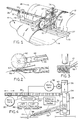
- an optical fiber 10 is shown being removed from a storage spool 12 and wound onto a cylindrical canister or drum 14 for ultimate use as a missile or vehicle data link, for example. Since the wound drum 14 may have to be stored for some time, either aboard the vehicle, or at some suitable storage facility, it is customary practice to apply an adhesive to the wound pack 16 which acts to maintain the dimensional and geometric integrity of the stack. As will be more particularly described, the apparatus identified generally as 18 applies a liquid adhesive onto the fiber at the point that it is being laid down onto the drum surface or onto an underlying fiber layer on the drum, as the case may be.
- the apparatus 18 for practicing the method of this invention includes a pair of elongated support rails 20 and 22 located between the storage spool 12 and drum 14, and generally parallel to the cylindrical axis of the canister drum.
- a vertically extending guide 24 has one end mounted onto a pair of rollers which are constructed at such geometry and dimensions as to enable receipt on the upper surfaces of the rails 20 and 22 and to roll therealong.
- a rack 26 has one end secured to the guide 24 and the remainder of which extends through an oversized opening in a vertically extending stanchion 28 end mounted to the rails 20 and 22.
- a servomotor 30 is affixed to the stanchion 28 and includes a drive gear 32 which meshes with teeth on the rack 26 for positioning the rack at any desired location horizontally along the rails 20 and 22, as will be more particularly described. Since the axis of the canister 14 is more frequently than not arranged horizontally during winding, the motor 30 will be referred to herein as the horizontal motor.
- the guide 24 also includes a central slot 34 through which a further rack 36 is slidingly received.
- a servomotor 38 is secured to the upper end of the guide and has a drive gear 40 which meshes with the rack 36 for drivingly positioning the rack at any desired vertical position along the guide 24.
- a pulley wheel 42 having a circumferential groove 44 is axially and rotatably mounted to the end of a support arm 46.
- An elongated slot 48 in arm 46 has a threaded member 50 enabling removable attachment of the arm to the rack 36.
- the arm 46 may be located at any desired angular position and spacing from the guide 24 by loosening and retightening the threaded member 50.
- the pulley wheel grooves 44 receives the fiber 10 therein and precisely locates the fiber during winding onto the drum 14 in a manner that will be more particularly described.
- a further arm 52 has an elongated slot 54 therein similarly secured to the rack 36 below the first elongated arm 46 and adjustably secured to the rack by a threaded bolt 56.
- a hollow tube 58 Secured to the outer end of the arm 52 is a hollow tube 58 with its longitudinal axis generally aligned to that of the arm 52, the tube opening having a cross-section in the order of 0.010 inches diameter.
- the tube is interconnected with a source of supply of liquid adhesive (not shown) maintaining a continuous supply at the tube outer end 60. More particularly, the adhesive volume being applied underneath a new winding is a function of the linear winding velocity.
- the servomotor operation is under control of a processor 62 responsive to a light beam reflected from the upper surface of the pack 16 and/or drum surface. More particularly, a light beam 64 from a source 66 is directed toward the upper surface of a fiber (or, optionally, a groove between adjacent fibers) which reflects to a light detector 68 where a signal is generated that is entered into the processor 62.
- the processor generates drive signals for both the horizontal and vertical motors to effecting both proper tracking of the winding in the current layer and raising the winding apparatus to accommodate the addition of layers.
- the processor controls an adhesive metering device 70 such that adhesive is continuously provided to the tube 58 in accordance with winding speed so that a very small amount of adhesive will be laid down underneath a new winding onto the drum or underlying winding, as the case may be.
- Winding a fiber onto a wet bead of adhesive also provides lubricity aiding uniform placement of the fiber.
- the operator may have to make manual adjustments to optimize adhesive application rate for current operating circumstances (e.g. canister configuration, relative humidity, adhesive used).
- the horizontal rack 26 is positioned at one end of the drum 14 and the vertical rack 36 is adjusted to the position for winding the first (lowermost) layer.
- a length of fiber 10 pulled off the storage spool has its end anchored to the drum and the fiber is threaded along the pulley groove.
- winding is begun which consists essentially of the fiber being placed at a precise location on the drum by the pulley wheel 42 under the control of the horizontal servomotor which incrementally moves the pulley wheel longitudinally of the drum.
- adhesive is metered from the tube 58 onto the drum surface (or fiber layer) immediately under the fiber leaving the pulley wheel. Winding in this way continues to finish a winding layer when the vertical servomotor moves the pulley and adhesive tube radially outward for a new layer, and a new winding is laid down in reverse direction.
- a continuous narrow strip or bead of adhesive is deposited onto the drum or underlying winding layer just as a new winding is about to be laid down.
- the strip or bead has a width approximately the same as that of the filament.
Landscapes
- Physics & Mathematics (AREA)
- General Physics & Mathematics (AREA)
- Optics & Photonics (AREA)
- Moulding By Coating Moulds (AREA)
- Light Guides In General And Applications Therefor (AREA)
- Unwinding Of Filamentary Materials (AREA)
- Filamentary Materials, Packages, And Safety Devices Therefor (AREA)
- Mechanical Coupling Of Light Guides (AREA)
- Coating Apparatus (AREA)
- Winding Filamentary Materials (AREA)
Claims (12)
- Procédé destiné à former une bobine de fil sur un tambour, les couches adjacentes de bobinage adhérant les unes aux autres tout en étant détachables, comprenant les étapes consistant à:
tourner axialement le tambour, une extrémité du fil y étant fixée afin d'enrouler le fil sur le tambour; et
mouiller continûment la surface du bobinage sous-jacent à l'aide d'un adhésif liquide juste sous, et immédiatement avant, un bobinage de fil en cours. - Procédé selon la revendication 1, dans lequel l'adhésif est posé en une bande de type à bourrelet ayant une largeur égale environ à celle du fil.
- Procédé selon la revendication 1, dans lequel l'adhésif est alimenté dans l'espace sous-jacent en une quantité qui est fonction de la vitesse linéaire de bobinage du fil.
- Procédé selon la revendication 1, dans lequel le mouillage à l'aide d'un adhésif s'accomplit en positionnant l'extrémité ouverte d'un tube sous le fil devant être enroulé sur le tambour et en mettant sous pression l'adhésif à travers le tube afin qu'il soit déposé sur le bobinage sous-jacent.
- Procédé selon la revendication 4, comprenant l'étape supplémentaire consistant à établir un mouvement relatif parallèle à l'axe du tambour, entre le tambour et le tube selon une direction qui fasse avancer de façon synchrone le mouillage du tambour et le bobinage du fil.
- Appareil destiné à appliquer un adhésif liquide alors qu'une fibre optique est en train d'être enroulée sur un tambour à partir d'une bobine de stockage, comprenant:
une roue de poulie guidant la fibre vers le tambour;
un tube creux dont une extrémité est située entre la fibre optique et le tambour en un point, après qu'elle a été guidée par la roue de poulie et avant que ladite fibre ait été enroulée sur le tambour; et
une source d'adhésif liquide sous pression connectée à l'autre extrémité du tube et fournissant une quantité minimale d'adhésif en vue de mouiller continûment la surface sous-jacente sur laquelle la fibre est en train d'être enroulée. - Appareil selon la revendication 6, dans lequel la roue de poulie posséde une rainure circonférentielle au sein de laquelle la fibre est reçue.
- Appareil selon la revendication 6, dans lequel le tube et la roue de poulie sont montés de façon unitaire, et des moyens sont prévus pour réaliser un mouvement relatif entre le tambour et la roue de poulie et le tube unis, selon les rayons du tambour et selon une trajectoire parallèle à l'axe du tambour.
- Appareil selon la revendication 8, dans lequel le tube et la roue de poulie peuvent être positionnés de façon réglable l'un par rapport à l'autre.
- Appareil selon la revendication 6, dans lequel des moyens interconnectent le tube et la source d'adhésif sous pression afin d'alimenter l'adhésif en une bande de type à bourrelet continue à partir de l'extrémité du tube.
- Appareil selon la revendication 10, dans lequel lesdits moyens alimentent l'adhésif en une quantité qui est fonction de la vitesse de bobinage de la fibre.
- Appareil selon la revendication 10, dans lequel la bande a une largeur égale environ à celle de la fibre.
Applications Claiming Priority (2)
| Application Number | Priority Date | Filing Date | Title |
|---|---|---|---|
| US41336089A | 1989-09-27 | 1989-09-27 | |
| US413360 | 1989-09-27 |
Publications (3)
| Publication Number | Publication Date |
|---|---|
| EP0420410A2 EP0420410A2 (fr) | 1991-04-03 |
| EP0420410A3 EP0420410A3 (en) | 1992-02-26 |
| EP0420410B1 true EP0420410B1 (fr) | 1995-01-11 |
Family
ID=23636938
Family Applications (1)
| Application Number | Title | Priority Date | Filing Date |
|---|---|---|---|
| EP90309215A Expired - Lifetime EP0420410B1 (fr) | 1989-09-27 | 1990-08-22 | Procédé et dispositif pour fournir un adhésif sur une fibre optique pendant bobinage |
Country Status (9)
| Country | Link |
|---|---|
| EP (1) | EP0420410B1 (fr) |
| JP (1) | JPH03149503A (fr) |
| KR (1) | KR940008675B1 (fr) |
| AU (1) | AU628640B2 (fr) |
| CA (1) | CA2023024A1 (fr) |
| DE (1) | DE69015940T2 (fr) |
| EG (1) | EG19605A (fr) |
| IL (1) | IL95361A (fr) |
| NO (1) | NO175471C (fr) |
Families Citing this family (2)
| Publication number | Priority date | Publication date | Assignee | Title |
|---|---|---|---|---|
| CA2704197C (fr) * | 1990-12-13 | 2011-01-04 | United States Surgical Corporation | Methode et appareil de recouvrement des sutures |
| KR20010069756A (ko) * | 2001-05-08 | 2001-07-25 | 유형선 | 소염진통제인 아세메타신을 함유하며 장관내 특히대장에서의 약물 방출 속도가 조절되는 약물 전달 체계에대한 약제학적 경구용 조성물 및 그에 대한 제조방법 |
Family Cites Families (6)
| Publication number | Priority date | Publication date | Assignee | Title |
|---|---|---|---|---|
| US4746080A (en) * | 1987-03-31 | 1988-05-24 | The Boeing Company | Method of winding optical fiber on a bobbin |
| JP2607530B2 (ja) * | 1987-07-22 | 1997-05-07 | 海洋科学技術センタ− | 光ファイバスプール |
| DE3743484A1 (de) * | 1987-12-22 | 1989-07-13 | Philips Patentverwaltung | Verfahren zur herstellung einer auf eine maschinenspule gewickelten ader |
| DE68908882T2 (de) * | 1988-11-23 | 1993-12-16 | Hughes Aircraft Co | Faseroptischer trommelklebstoff und dessen verwendung. |
| US4950049A (en) * | 1989-02-28 | 1990-08-21 | At&T Bell Laboratories | Stable package of elongated optical fiber strand material |
| US4957344A (en) * | 1989-04-18 | 1990-09-18 | Hughes Aircraft Company | Optical fiber tape assembly and canister |
-
1990
- 1990-08-09 CA CA002023024A patent/CA2023024A1/fr not_active Abandoned
- 1990-08-13 IL IL9536190A patent/IL95361A/en active IP Right Review Request
- 1990-08-22 DE DE69015940T patent/DE69015940T2/de not_active Expired - Fee Related
- 1990-08-22 EP EP90309215A patent/EP0420410B1/fr not_active Expired - Lifetime
- 1990-09-05 AU AU62212/90A patent/AU628640B2/en not_active Ceased
- 1990-09-06 NO NO903891A patent/NO175471C/no unknown
- 1990-09-26 JP JP2256756A patent/JPH03149503A/ja active Pending
- 1990-09-26 KR KR1019900015266A patent/KR940008675B1/ko not_active Expired - Fee Related
- 1990-09-26 EG EG57090A patent/EG19605A/xx active
Also Published As
| Publication number | Publication date |
|---|---|
| NO903891L (no) | 1991-04-02 |
| DE69015940D1 (de) | 1995-02-23 |
| AU6221290A (en) | 1991-04-11 |
| KR910006125A (ko) | 1991-04-27 |
| KR940008675B1 (ko) | 1994-09-24 |
| AU628640B2 (en) | 1992-09-17 |
| IL95361A0 (en) | 1991-06-30 |
| IL95361A (en) | 1996-03-31 |
| EG19605A (en) | 1996-10-31 |
| CA2023024A1 (fr) | 1991-03-28 |
| EP0420410A3 (en) | 1992-02-26 |
| NO903891D0 (no) | 1990-09-06 |
| EP0420410A2 (fr) | 1991-04-03 |
| NO175471C (no) | 1994-10-19 |
| JPH03149503A (ja) | 1991-06-26 |
| NO175471B (no) | 1994-07-11 |
| DE69015940T2 (de) | 1995-05-11 |
Similar Documents
| Publication | Publication Date | Title |
|---|---|---|
| EP1242802B1 (fr) | Procede et appareil destines a l'essai de traction et a la reinsertion de fibre optique pendant le fibrage de fibre | |
| US5364489A (en) | Apparatus for applying adhesive to an optical fiber during winding | |
| US4978413A (en) | In-line filament cleaner and adhesive applicator | |
| JPH0573663B2 (fr) | ||
| WO2014048440A1 (fr) | Fabrication automatisée de composants d'éolienne | |
| EP0372258A2 (fr) | Procédé et dispositif de réglage d'une largeur de balayage présélectionnée d'un balai rotatif cylindrique | |
| US5409535A (en) | Apparatus for imparting a sliding capacity to a wire | |
| EP0420410A2 (fr) | Procédé et dispositif pour fournir un adhésif sur une fibre optique pendant bobinage | |
| CN103241588B (zh) | 确定筒子驱动辊的所需转速的方法和装置 | |
| DE19650879A1 (de) | Kreuzspulen herstellende Textilmaschine | |
| US3961153A (en) | Machine for fabricating a wire network | |
| US5186781A (en) | Application of adhesive during optical fiber canister winding | |
| DE4314393A1 (de) | Verfahren zum Schären von Fäden sowie Schärmaschine | |
| AU749925B2 (en) | Producing optical fibre | |
| US4531689A (en) | Vacuum probe for attaching tape to reel hub within a cartridge | |
| US6001006A (en) | Machine for machining internal surfaces of axisymmetric workpieces using an abrasive strip | |
| JP2007260974A (ja) | フィラメントワインディング装置 | |
| DE3343285A1 (de) | Vorrichtung zum abspulen eines wickelguts | |
| US4960068A (en) | Fiber gauging guide for an in-line optical fiber adhesive applicator | |
| DE69023740T2 (de) | Faserausgabemaschine. | |
| EP0534408A1 (fr) | Appareil et méthode pour filer un matériau filiforme | |
| JPH0655129A (ja) | 塗布体の製造方法 | |
| EP1707523A1 (fr) | Méthode et dispositif pour rebobiner des fils textiles | |
| WO1995015263A1 (fr) | Procede et appareil de reencrage du ruban encreur d'imprimante | |
| US3791901A (en) | Method and apparatus for making potentiometer windings |
Legal Events
| Date | Code | Title | Description |
|---|---|---|---|
| PUAI | Public reference made under article 153(3) epc to a published international application that has entered the european phase |
Free format text: ORIGINAL CODE: 0009012 |
|
| AK | Designated contracting states |
Kind code of ref document: A2 Designated state(s): CH DE FR GB IT LI NL SE |
|
| PUAL | Search report despatched |
Free format text: ORIGINAL CODE: 0009013 |
|
| AK | Designated contracting states |
Kind code of ref document: A3 Designated state(s): CH DE FR GB IT LI NL SE |
|
| 17P | Request for examination filed |
Effective date: 19920803 |
|
| 17Q | First examination report despatched |
Effective date: 19940201 |
|
| GRAA | (expected) grant |
Free format text: ORIGINAL CODE: 0009210 |
|
| AK | Designated contracting states |
Kind code of ref document: B1 Designated state(s): CH DE FR GB IT LI NL SE |
|
| PG25 | Lapsed in a contracting state [announced via postgrant information from national office to epo] |
Ref country code: NL Effective date: 19950111 |
|
| REF | Corresponds to: |
Ref document number: 69015940 Country of ref document: DE Date of ref document: 19950223 |
|
| ET | Fr: translation filed | ||
| ITF | It: translation for a ep patent filed | ||
| PG25 | Lapsed in a contracting state [announced via postgrant information from national office to epo] |
Ref country code: SE Effective date: 19950411 |
|
| NLV1 | Nl: lapsed or annulled due to failure to fulfill the requirements of art. 29p and 29m of the patents act | ||
| PLBE | No opposition filed within time limit |
Free format text: ORIGINAL CODE: 0009261 |
|
| STAA | Information on the status of an ep patent application or granted ep patent |
Free format text: STATUS: NO OPPOSITION FILED WITHIN TIME LIMIT |
|
| 26N | No opposition filed | ||
| PGFP | Annual fee paid to national office [announced via postgrant information from national office to epo] |
Ref country code: FR Payment date: 19960711 Year of fee payment: 7 |
|
| PGFP | Annual fee paid to national office [announced via postgrant information from national office to epo] |
Ref country code: GB Payment date: 19960723 Year of fee payment: 7 |
|
| PGFP | Annual fee paid to national office [announced via postgrant information from national office to epo] |
Ref country code: DE Payment date: 19960724 Year of fee payment: 7 Ref country code: CH Payment date: 19960724 Year of fee payment: 7 |
|
| PG25 | Lapsed in a contracting state [announced via postgrant information from national office to epo] |
Ref country code: GB Free format text: LAPSE BECAUSE OF NON-PAYMENT OF DUE FEES Effective date: 19970822 |
|
| PG25 | Lapsed in a contracting state [announced via postgrant information from national office to epo] |
Ref country code: LI Free format text: LAPSE BECAUSE OF NON-PAYMENT OF DUE FEES Effective date: 19970831 Ref country code: CH Free format text: LAPSE BECAUSE OF NON-PAYMENT OF DUE FEES Effective date: 19970831 |
|
| GBPC | Gb: european patent ceased through non-payment of renewal fee |
Effective date: 19970822 |
|
| REG | Reference to a national code |
Ref country code: CH Ref legal event code: PL |
|
| PG25 | Lapsed in a contracting state [announced via postgrant information from national office to epo] |
Ref country code: FR Free format text: LAPSE BECAUSE OF NON-PAYMENT OF DUE FEES Effective date: 19980430 |
|
| PG25 | Lapsed in a contracting state [announced via postgrant information from national office to epo] |
Ref country code: DE Free format text: LAPSE BECAUSE OF NON-PAYMENT OF DUE FEES Effective date: 19980501 |
|
| REG | Reference to a national code |
Ref country code: FR Ref legal event code: ST |
|
| PG25 | Lapsed in a contracting state [announced via postgrant information from national office to epo] |
Ref country code: IT Free format text: LAPSE BECAUSE OF NON-PAYMENT OF DUE FEES Effective date: 20050822 |