EP0420414A2 - Gerät zum Aufbrechen oder Anritzen von OberflÀ¤chen - Google Patents
Gerät zum Aufbrechen oder Anritzen von OberflÀ¤chen Download PDFInfo
- Publication number
- EP0420414A2 EP0420414A2 EP90309360A EP90309360A EP0420414A2 EP 0420414 A2 EP0420414 A2 EP 0420414A2 EP 90309360 A EP90309360 A EP 90309360A EP 90309360 A EP90309360 A EP 90309360A EP 0420414 A2 EP0420414 A2 EP 0420414A2
- Authority
- EP
- European Patent Office
- Prior art keywords
- tool
- teeth
- disc
- relative
- discs
- Prior art date
- Legal status (The legal status is an assumption and is not a legal conclusion. Google has not performed a legal analysis and makes no representation as to the accuracy of the status listed.)
- Granted
Links
Images




Classifications
-
- E—FIXED CONSTRUCTIONS
- E01—CONSTRUCTION OF ROADS, RAILWAYS, OR BRIDGES
- E01H—STREET CLEANING; CLEANING OF PERMANENT WAYS; CLEANING BEACHES; DISPERSING OR PREVENTING FOG IN GENERAL CLEANING STREET OR RAILWAY FURNITURE OR TUNNEL WALLS
- E01H5/00—Removing snow or ice from roads or like surfaces; Grading or roughening snow or ice
- E01H5/12—Apparatus or implements specially adapted for breaking, disintegrating, or loosening layers of ice or hard snow with or without clearing or removing ; Roughening ice or hard snow by means of tools
-
- B—PERFORMING OPERATIONS; TRANSPORTING
- B28—WORKING CEMENT, CLAY, OR STONE
- B28D—WORKING STONE OR STONE-LIKE MATERIALS
- B28D1/00—Working stone or stone-like materials, e.g. brick, concrete or glass, not provided for elsewhere; Machines, devices, tools therefor
- B28D1/18—Working stone or stone-like materials, e.g. brick, concrete or glass, not provided for elsewhere; Machines, devices, tools therefor by milling, e.g. channelling by means of milling tools
- B28D1/181—Working stone or stone-like materials, e.g. brick, concrete or glass, not provided for elsewhere; Machines, devices, tools therefor by milling, e.g. channelling by means of milling tools using cutters loosely mounted on a turning tool support
-
- B—PERFORMING OPERATIONS; TRANSPORTING
- B44—DECORATIVE ARTS
- B44C—PRODUCING DECORATIVE EFFECTS; MOSAICS; TARSIA WORK; PAPERHANGING
- B44C7/00—Paperhanging
- B44C7/02—Machines, apparatus, tools or accessories therefor
- B44C7/027—Machines, apparatus, tools or accessories for removing wall paper
Definitions
- This invention relates to surface breaking or scarifying tools having rotatable rollers, discs or cutters capable of being moved over a surface to be cut or scratched.
- Such scarifying tools are used to perforate wallpaper, and also to break the surface of the ice on car windscreens, footpaths, steps or the like to assist in removing it.
- a disadvantage hitherto associated with such an arrangement has been that although the tool is moved back and forth across the surface in a scrubbing type of motion, it only cuts into the surface while moving in one direction, and has little or no effect on the surface on the return stroke. It has also been found difficult to provide a simple and effective means for precisely limiting the depth of penetration of the cutters on a surface such as wallpaper, particularly on uneven surfaces such as embossed or textured wallpaper.
- the present invention provides a tool for scarifying a surface or removing ice therefrom, including: at least one pair of rotatably mounted opposing discs; each said disc including a central aperture by which the disc is mounted on an axle to rotate relative to the axle, a plurality of sharp teeth radiating outwardly from the rim of said disc and depth control means, rotatable with said disc on said disc axle, lying transversely relative to said teeth and adjacent said teeth.
- said teeth radiate conically outward from the rim of said disc, inclined out of a plane orthogonal to said axle.
- said depth control means comprises a second plurality of sharp teeth, radiating conically outward from the rim of said disc, inclined out of said plane on the opposite side from the first said plurality of teeth so as to project transversely relative to the first said plurality of teeth; said first and second pluralities of teeth being arranged to alternate around the rim of said disc.
- the invention provides a tool including a carriage element on which said at least one pair of discs is mounted, said element being movable relative to a body of said tool, such that said disc axles can be moved to at least two different orientations relative to said body; wherein at each said orientation said discs are non-parallel with respect to each other, with respect to a direction of travel of the tool and with respect to a line orthogonal to the surface at a point of contact between said surface and said disc; whereby in use movement of the tool in a said direction of travel can cause said discs to roll and impart opposed sideways forces on said surface at spaced apart positions of contact with the surface.
- the carriage element is movable about a carriage axis of rotation substantially orthogonal to a plane of symmetry between said non-parallel disc axles, such that said carriage element can be pitched at different angles within said plane of symmetry, different said angles providing different said orientations of the disc axles relative to the body.
- a wide variety of tools have hitherto been known for the purpose of scarifying or puncturing wallpaper, so as to allow water or some other solvent to seep in behind the paper and thereby make it easier to remove.
- Such tools have often included some form of serrated edge or wheel which is dragged across the surface of the wallpaper. It has been found preferable with such tools to drive the teeth into the paper obliquely by some means, rather than straight down, so that the tool does not need to be pressed heavily against the wall to penetrate the paper, but rather so that the movement of the tool across the wall helps drive the teeth into the paper.
- the preferred form of the present invention includes a pair of cutter wheels 14 and 15, which can readily provide an oblique piercing action as the tool is moved across a surface.
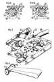
- the cutter wheels 14 and 15, illustrated in figures 2 and 3, are preferably formed with sharp radial teeth around the entire outer circumference, alternately inclined to one side or the other so as to provide a bank of generally outwardly projecting teeth 16 (relative to a body 12 in the center) and a bank of generally inwardly projecting teeth 17.
- This form of wheel may conveniently be provided by the use of two pressed metal discs 18 brought together face to face as shown in figure 2, with the inclined teeth of one in register with the gaps between teeth of the other.
- Such wheels 14 and 15 could be used in a mono-directional cutter, as shown in figure 8, if mounted on fixed axles connected to a handle and inclined so as to converge (for example) towards the front and top of the wheels. If arranged to converge towards the top, the inwardly projecting teeth 17 on each wheel will be angled down into paper on which the tool is used, while the outwardly projecting teeth 16 lie nearly parallel with the paper, and act as guards to prevent the downwardly projecting teeth 16 from penetrating too deeply. If with such an arrangement the wheels 14 and 15 are also arranged to converge towards the front of the tool, the inwardly projecting teeth 17 will converge as they roll down onto the paper when the tool is pulled backwards and will cut inwards before tearing back up through the paper.
- the wheels 14 and 15 may be arranged to converge towards the bottom, such that the outwardly projecting teeth 16 are angled more downwardly into the paper while the inwardly projecting teeth 17 lie on the surface of the paper and act as depth guards.
- the teeth will drive into the paper when movement of the tool causes them to diverge as they contact the paper, and conversely they will not penetrate the paper when moved so as to converge, on the return stroke.
- the preferred apparatus of the present invention provides means by which the paper can be cut both when the tool is moved forwards and when it is moved backwards, comprising a hand held tool incorporating one or more cutting heads 10 as shown in Figure 1.
- the handle portion may take any of a variety of known forms, and may conveniently be fixed to the cutting head 10 by fasteners such as screws, bolts or the like passed through retaining holes 11.
- the cutting head 10 has four principal components, these being a body 12 through which the holes 11 pass, a rolling or pivoting block 13 mounted under the body, and two cutter wheels 14 and 15 rotatably mounted on the block 13 to either side of the body 12.
- axles 19 are mounted on the rolling or pivoting block 13, which shifts as the direction of movement of the tool is reversed, so as to change the orientation of the wheels to suit the change in direction.
- the block 13 as shown in figure 4 is preferably generally cylindrical in shape, with end walls 20 and 21 converging as shown, so that the end walls are closest together at the point 22, and furthest apart at the point 23.
- the curved side of the cylinder is provided with a rack of notches 24, which in use engage with corresponding teeth 25 on the body 12.
- Annular flanges 26 may be provided to either side of the notched area as shown, which in normal use run along either side of the body 12 and act to retain the block 13 in position relative to the body 12.
- Axles 19 are in normal use mounted in apertures 27 in either end wall, so as to project orthogonally relative to that end wall, rather than parallel to the general axis of the block 13.
- the wheel 14 will therefore rotate in a plane parallel to the end wall 20, and the wheel 15 will rotate in a plane parallel to the end wall 21.
- the block 13 is held in association with the body 12 by the flanges 26 and by a bracket element 28, with the teeth 25 on the body engaged with the notches 24 on the block.
- the bracket 28 is longer than the diameter of the block 13, and consequently the block 13 is able to roll along the body 12 a short distance, with the racks of teeth 25 and notches 24 still in engagement. As shown in figures 5 and 6, this allows the block to move between two extreme positions.
- Movement of the tool will tend to roll the block 13 into one of these two positions, where it is prevented from further rolling by the termination of the racks of teeth 25 and notches 24 and by the end wall of the bracket 28 (not shown in figures 5 and 6).
- the wheels 14 and 15 in normal use will rotate on their axles 19 instead.
- the block 13 is at one end of the rack of teeth 25, and will not in normal use roll any further (being held by the bracket 28, not shown).
- the wheels 14 and 15 lie in planes inclined at an angle of approximately 5° from orthogonal to the surface to be scarified, or between 2° and 10° from orthogonal, and at an angle of approximately 20°, or between 10° and 30°, to the direction of travel of the tool. It will be appreciated that as the block 13 is rotated, the inclination of the wheels relative to the surface will increase, and the inclination of the wheels relative to the direction of travel proportionately decrease, or vice versa.
- the point 22 is now positioned towards the bottom and back of the block 13, rather than the top and back, and correspondingly, the point 23 of greatest divergence is positioned towards the front and top of the block 13. Because the point 22 is now towards the bottom rather than the top, the outwardly projecting teeth 16 are now angled downwardly into the paper 30, rather than the inwardly projecting teeth 17. As the tool is moved back in the direction of arrow 32, the teeth 16 in contact with the paper are driven outwardly, as they rotate from the point 22 of greatest convergence towards the point 23 of greatest divergence. This acts to drive the teeth 16 into the paper.
- cutting heads 10 of the present invention are incorporated into a tool 33 as shown in figure 7, having three such cutter heads arranged in parallel configuration and spaced apart as shown.
- a handle 34 is provided on the upper face of the tool, and preferably a source of steam, water or other solvent is also provided, connected to an outlet 35 in the body of the tool 33 by a pipe 36.
- the solvent can be applied to the surface and pass through the holes in the paper as they are created by the cutting heads 10.
- the water, steam or other solvent might be applied as a separate operation, and the tool 33 comprise a scarifying tool only, or the tool might include a water reservoir as an integral part of the unit.
- the rolling block element 13 is not the only means by which the axles 19 or axes of rotation of the wheels 14 and 15, can be rotated relative to the surface to be scarified.
- a pivotal arrangement can be used to achieve the same result.
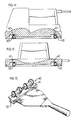
- a pair of wheels 14 and 15 are arranged in a cutting head 40, comprised of a socket 41 in a tool body 42, and a pivotal element 43 on which the wheels 14 and 15 are rotatably mounted.
- the axes of rotation of the wheel 14 and 15 are not parallel, but rather are arranged at an angle to each other so that the wheels 14 and 15 converge towards one side 22 and diverge towards the other 23.
- the element 43 includes a head portion 44 adapted to pivotally fit into and be retained in the socket 41, a stem or leg 45 depending from the head 44 and a base 46.
- the base 46 may take a variety of forms, but preferably is generally cruciform, or T or Y-shaped in cross-section, having flanges 47 to provide lateral support for the rims of the wheels 14 and 15 while at the same time not giving too large an area of frictional contact between the sides of the base 46 and the inside surfaces of the wheels.
- the element 43 is formed from a material such as nylon, which is slightly resilient to facilitate snap-fitting into the socket 41, and also preferably does not require lubrication at the pivot head or axle mounting.
- the top face 48 of the head portion 44 is preferably slightly convex as shown, and allowed a small degree of rolling movement in a lateral plane. This allows the element 43 to roll slightly and thereby compensate for unevenness in the surface to be scarified, so that such unevenness or irregularity will not result in one wheel of the pair losing contact with the surface. It should be appreciated that the pair of wheels act in concert to some extent, each bearing against the other to drive the teeth 16 or 17 into the surface.
- the portion of the tool body 42 housing the socket 41 might be movably connected to the remainder of the body 42, so that substantially the whole cutting head 40 can "float" relative to the handle of the tool, and other associated cutting heads or bearing elements bearing on the same surface.
- cutting heads of the present invention might be removably attached to a variety of tools, adapted for the purpose by the provision of one or more sockets 41.
- the cutting heads may enhance the ordinary or usual function of the tool, by perforating a surface as it is steamed, to facilitate entry of the steam into and behind the surface and thereby assist in removing paper or a like covering.
- the cutting heads may provide an additional or secondary function for the tool rather than enhancing the primary function.
- interior decorators or home renovators commonly own and use one or more such pieces of equipment, and will often find it advantageous to be able to use the same equipment for the purpose of scarifying a surface.
- the sockets 41 may be provided in the body of the tool itself or, as shown in Figure 13, might be provided on a separate frame or body 51, which can be fastened to the tool by screw fasteners, clamping means or the like (not shown).
- the sockets are positioned so that the tool may still be used for its primary purpose while the cutting heads are in place, as illustrated in Figures 15 and 17, by reversing and/or tilting the tool, but because the cutting heads 40 can quite readily be removed and replaced in the sockets 41, it may be found quite feasible in practice to alter the tool by adding or removing cutting heads 40, and to adapt it solely for one purpose or another.
- the cutting wheels 14 and 15 While it is preferable for the cutting wheels 14 and 15 to have two rows of teeth, 16 and 17, one of which acts to cut into the paper and the other of which acts as a depth guard to prevent the tool from cutting too deeply, it may be possible to provide a cutting head having only (for example) inwardly projecting teeth, wherein the point at which the wheels are closest together rolls or pivots from a top-back position to a top-front position when the direction of movement changes, rather than from top-back to bottom-back as in the example described above. In such a case a blunt-toothed wheel could be provided as an outwardly projecting depth guard, or some other means used to achieve the same object.
- Such an arrangement is particularly suitable for use on ice - breaking tools, which preferably have very widely splayed wheels, lying almost parallel to the surface being cut.
- This arrangement directs the force provided by movement of the tool more into the sideways movement of the teeth, and less into the downward penetration of the surface, than with a tool with more upright wheels. It will be appreciated that when the wheels are lying flat in this fashion it is generally inconvenient to flip them over so as to employ a second set of teeth on the return stroke of the tool, and generally more convenient to reverse the inclination of the wheels, so that it remains the same with respect to the direction of travel in the reverse direction.
- the block could be arranged to roll or pivot through approximately 180 o , rather than approximately 90° as in the examples above, to present different wheel arrangements when moving in different directions.
- movement of the block or equivalent be minimized, because the teeth do not cut the surface while the block is rolling, and consequently such rolling reduces the efficiency of the cutting stroke.
- the degree of roll or pivot it may generally be found more preferable for the degree of roll or pivot to be less than 90°, rather than greater.
- wheels and the tool might be provided on a tool intended for scarifying ice on car windscreens, so as to remove it without risk of scratching or otherwise damaging the windscreen itself.
- a considerably larger tool might be provided, having larger cutting wheels mounted in the same way and pivotally fixed to a broom or spade type handle, for use in removing ice from road or pavement surfaces.
- the wheels might also be made with separate tooth or pin elements clamped or otherwise fixed onto wheel hubs, rather than having teeth formed as an integral part of the wheel, by stamping, molding or the like.
- the form of the block 13 might also be altered considerably, possibly with corresponding changes in the body 12.
- the racks of teeth and notches by which the block and body are engaged may take a variety of forms, but should provide secure engagement without inhibiting the rolling action of the block, so as to avoid slipping or jamming.
- the block 13 might be rotatably mounted on an axle rather than arranged to roll back and forth, but the additional complexity of construction involved in such an embodiment makes it appear less preferable at present.
- Each cutting wheel might be individually mounted on a separate block or axle arrangement, rather than being mounted in pairs as illustrated above, but this also appears less desirable at present.
Landscapes
- Engineering & Computer Science (AREA)
- Architecture (AREA)
- Civil Engineering (AREA)
- Structural Engineering (AREA)
- Mining & Mineral Resources (AREA)
- Mechanical Engineering (AREA)
- Treatment Of Fiber Materials (AREA)
- Synthetic Leather, Interior Materials Or Flexible Sheet Materials (AREA)
- Paper (AREA)
- Polishing Bodies And Polishing Tools (AREA)
- Electrical Discharge Machining, Electrochemical Machining, And Combined Machining (AREA)
- Food-Manufacturing Devices (AREA)
Priority Applications (1)
| Application Number | Priority Date | Filing Date | Title |
|---|---|---|---|
| AT90309360T ATE96379T1 (de) | 1989-08-31 | 1990-08-28 | Geraet zum aufbrechen oder anritzen von oberflaechen. |
Applications Claiming Priority (2)
| Application Number | Priority Date | Filing Date | Title |
|---|---|---|---|
| NZ230500 | 1989-08-31 | ||
| NZ23050089 | 1989-08-31 |
Publications (3)
| Publication Number | Publication Date |
|---|---|
| EP0420414A2 true EP0420414A2 (de) | 1991-04-03 |
| EP0420414A3 EP0420414A3 (en) | 1991-07-31 |
| EP0420414B1 EP0420414B1 (de) | 1993-10-27 |
Family
ID=19922954
Family Applications (1)
| Application Number | Title | Priority Date | Filing Date |
|---|---|---|---|
| EP90309360A Expired - Lifetime EP0420414B1 (de) | 1989-08-31 | 1990-08-28 | Gerät zum Aufbrechen oder Anritzen von Oberflächen |
Country Status (5)
| Country | Link |
|---|---|
| US (1) | US5074045A (de) |
| EP (1) | EP0420414B1 (de) |
| AT (1) | ATE96379T1 (de) |
| CA (1) | CA2024116C (de) |
| DE (1) | DE69004207D1 (de) |
Cited By (5)
| Publication number | Priority date | Publication date | Assignee | Title |
|---|---|---|---|---|
| DE4206823A1 (de) * | 1992-03-04 | 1993-09-09 | Helmuth Umbehr | Vorrichtung zur mechanischen bearbeitung einer oberflaeche oder einer vielzahl von schaftfoermigen gegenstaenden |
| EP0634296A1 (de) * | 1993-07-14 | 1995-01-18 | Elias Lebessis | Reisswerkzeug zum Aufreissen von Schichtmaterial |
| GB2360480A (en) * | 2000-03-22 | 2001-09-26 | Archie Newton | Wallpaper surface breaker |
| WO2008124398A1 (en) * | 2007-04-05 | 2008-10-16 | Wagner Spray Tech Corporation | Wallpaper removal tool comprising scoring wheels and a liquid applicator |
| GB2499064A (en) * | 2012-08-13 | 2013-08-07 | Irfan Ali Fazal | Apparatus for removing wall covering |
Families Citing this family (11)
| Publication number | Priority date | Publication date | Assignee | Title |
|---|---|---|---|---|
| US5533987A (en) * | 1992-04-09 | 1996-07-09 | Scimed Lifesystems, Inc. | Dilatation catheter with polymide encased stainless steel braid proximal shaft |
| US5643403A (en) * | 1994-12-19 | 1997-07-01 | Robert N. Poole | Wall covering removal system with a surface cleaning apparatus and a surface scarifying apparatus |
| US5950312A (en) * | 1997-06-18 | 1999-09-14 | William Zinsser & Co., Incorporated | Wallpaper scarifying device |
| US6163966A (en) * | 1998-08-17 | 2000-12-26 | Jackson; Richard L. | Scoring tool |
| US20130267959A1 (en) * | 2001-06-14 | 2013-10-10 | Alexandria Research Technologies, Inc. | Modular apparatus and method for sculpting the surface of a joint |
| US7694422B2 (en) * | 2006-10-17 | 2010-04-13 | Ed Vaes | Utility knife |
| CA2646610A1 (en) * | 2007-12-19 | 2009-06-19 | Ed Vaes | Wheels for knives and screening tools |
| US20130327199A1 (en) * | 2012-06-11 | 2013-12-12 | Dwayne EAGLE | Rolling Tool |
| US8726966B1 (en) * | 2013-01-28 | 2014-05-20 | Eric Liao | Adhesive substance removing tool |
| DE102013102019B8 (de) * | 2013-02-28 | 2015-11-05 | Eric Liao | Gerät zum Perforieren und Entfernen von geklebten Gegenständen |
| CN111794170B (zh) * | 2020-07-20 | 2022-03-25 | 长春市布拉德除雪机械有限公司 | 一种除雪设备及其除冰装置 |
Family Cites Families (9)
| Publication number | Priority date | Publication date | Assignee | Title |
|---|---|---|---|---|
| US1040241A (en) * | 1912-02-07 | 1912-10-01 | Louis J Rouchleau | Parachute. |
| US3514854A (en) * | 1967-09-28 | 1970-06-02 | John H Norfleet | Scarifier for use in removing wallpaper or the like |
| US3708880A (en) * | 1970-08-17 | 1973-01-09 | J Norfleet | Scarifier for wall coverings |
| US4365430A (en) * | 1981-06-29 | 1982-12-28 | Myerly James W | Snow removal accessory for snow throwing devices |
| NZ198688A (en) * | 1981-10-19 | 1986-02-21 | P A M Brookfield | Wallpaper scarifying roller:inclined and angled pair of rotatable gripping discs |
| CA1187909A (en) * | 1983-03-04 | 1985-05-28 | Rene Vachon | Snowblower and scarifying auger assembly therefor |
| US4546513A (en) * | 1984-03-22 | 1985-10-15 | Hammond Michael D | Ice breaker and scraper |
| DE3785517T2 (de) * | 1986-08-26 | 1993-09-09 | Komatsu Zenoa Kk | Maehmaschine. |
| US4858321A (en) * | 1988-03-04 | 1989-08-22 | Mccullough Timothy J | Slotted depth gauge plate |
-
1990
- 1990-08-20 US US07/570,955 patent/US5074045A/en not_active Expired - Lifetime
- 1990-08-28 CA CA002024116A patent/CA2024116C/en not_active Expired - Fee Related
- 1990-08-28 DE DE90309360T patent/DE69004207D1/de not_active Expired - Lifetime
- 1990-08-28 AT AT90309360T patent/ATE96379T1/de active
- 1990-08-28 EP EP90309360A patent/EP0420414B1/de not_active Expired - Lifetime
Cited By (6)
| Publication number | Priority date | Publication date | Assignee | Title |
|---|---|---|---|---|
| DE4206823A1 (de) * | 1992-03-04 | 1993-09-09 | Helmuth Umbehr | Vorrichtung zur mechanischen bearbeitung einer oberflaeche oder einer vielzahl von schaftfoermigen gegenstaenden |
| EP0634296A1 (de) * | 1993-07-14 | 1995-01-18 | Elias Lebessis | Reisswerkzeug zum Aufreissen von Schichtmaterial |
| GB2360480A (en) * | 2000-03-22 | 2001-09-26 | Archie Newton | Wallpaper surface breaker |
| WO2008124398A1 (en) * | 2007-04-05 | 2008-10-16 | Wagner Spray Tech Corporation | Wallpaper removal tool comprising scoring wheels and a liquid applicator |
| GB2499064A (en) * | 2012-08-13 | 2013-08-07 | Irfan Ali Fazal | Apparatus for removing wall covering |
| GB2499064B (en) * | 2012-08-13 | 2014-01-01 | Irfan Ali Fazal | Apparatus for removing wallcoverings |
Also Published As
| Publication number | Publication date |
|---|---|
| EP0420414A3 (en) | 1991-07-31 |
| DE69004207D1 (de) | 1993-12-02 |
| ATE96379T1 (de) | 1993-11-15 |
| US5074045A (en) | 1991-12-24 |
| CA2024116C (en) | 2001-06-12 |
| CA2024116A1 (en) | 1991-03-01 |
| EP0420414B1 (de) | 1993-10-27 |
Similar Documents
| Publication | Publication Date | Title |
|---|---|---|
| EP0420414B1 (de) | Gerät zum Aufbrechen oder Anritzen von Oberflächen | |
| US4502223A (en) | Hand tool with toothed rotors for dislodging material from a surface | |
| US4668017A (en) | Stripping machine | |
| EP0284391B1 (de) | Befestigung der Schneidfinger einer Schälmaschine | |
| US7033258B2 (en) | Floor resurfacing disks for rotary floor resurfacing machines | |
| US4009908A (en) | Carpet and tile stripper | |
| US4099328A (en) | Machine for removing floor covering | |
| WO2011011732A2 (en) | Trenching system | |
| US4592108A (en) | Tool and method for scarifying a surface | |
| JP2015513019A (ja) | 路面処理用の自走式道路切削機、及び路面処理方法 | |
| CA1305299C (en) | Surface stripping device | |
| US5058275A (en) | Chisel | |
| US7055201B2 (en) | Surface treating machine | |
| KR101914745B1 (ko) | 빙면의 투과율 및 반사율을 향상시키기 위한 빙판 연마용 정빙차 | |
| US4437523A (en) | Lawn edging device | |
| US2552382A (en) | Rotary brush for lawn sweepers | |
| US20250067011A1 (en) | Ice edger brush apparatus | |
| WO2023079253A1 (en) | Floor treatment machine | |
| JPH06173217A (ja) | 舗装面のゴム等の除去洗浄装置 | |
| JPH0322983Y2 (de) | ||
| JPH0242825Y2 (de) | ||
| GB2122883A (en) | Method and apparatus for cleaning carpets | |
| US1853470A (en) | Tool for smoothing wooden surfaces | |
| RU2267575C2 (ru) | Устройство для очистки поверхности от льда, уплотненного снега и/или обработки грунта | |
| JPH0352919Y2 (de) |
Legal Events
| Date | Code | Title | Description |
|---|---|---|---|
| PUAI | Public reference made under article 153(3) epc to a published international application that has entered the european phase |
Free format text: ORIGINAL CODE: 0009012 |
|
| AK | Designated contracting states |
Kind code of ref document: A2 Designated state(s): AT BE CH DE DK FR GB IT LI NL SE |
|
| PUAL | Search report despatched |
Free format text: ORIGINAL CODE: 0009013 |
|
| AK | Designated contracting states |
Kind code of ref document: A3 Designated state(s): AT BE CH DE DK FR GB IT LI NL SE |
|
| 17P | Request for examination filed |
Effective date: 19920130 |
|
| 17Q | First examination report despatched |
Effective date: 19920616 |
|
| GRAA | (expected) grant |
Free format text: ORIGINAL CODE: 0009210 |
|
| AK | Designated contracting states |
Kind code of ref document: B1 Designated state(s): AT BE CH DE DK FR GB IT LI NL SE |
|
| PG25 | Lapsed in a contracting state [announced via postgrant information from national office to epo] |
Ref country code: IT Free format text: LAPSE BECAUSE OF FAILURE TO SUBMIT A TRANSLATION OF THE DESCRIPTION OR TO PAY THE FEE WITHIN THE PRE;WARNING: LAPSES OF ITALIAN PATENTS WITH EFFECTIVE DATE BEFORE 2007 MAY HAVE OCCURRED AT ANY TIME BEFORE 2007. THE CORRECT EFFECTIVE DATE MAY BE DIFFERENT FROM THE ONE RECORDED.SCRIBED TIME-LIMIT Effective date: 19931027 Ref country code: SE Effective date: 19931027 Ref country code: DE Effective date: 19931027 Ref country code: NL Effective date: 19931027 Ref country code: BE Effective date: 19931027 Ref country code: CH Effective date: 19931027 Ref country code: AT Effective date: 19931027 Ref country code: LI Effective date: 19931027 Ref country code: DK Effective date: 19931027 Ref country code: FR Effective date: 19931027 |
|
| REF | Corresponds to: |
Ref document number: 96379 Country of ref document: AT Date of ref document: 19931115 Kind code of ref document: T |
|
| REF | Corresponds to: |
Ref document number: 69004207 Country of ref document: DE Date of ref document: 19931202 |
|
| REG | Reference to a national code |
Ref country code: CH Ref legal event code: PL |
|
| EN | Fr: translation not filed | ||
| NLV1 | Nl: lapsed or annulled due to failure to fulfill the requirements of art. 29p and 29m of the patents act | ||
| PLBE | No opposition filed within time limit |
Free format text: ORIGINAL CODE: 0009261 |
|
| STAA | Information on the status of an ep patent application or granted ep patent |
Free format text: STATUS: NO OPPOSITION FILED WITHIN TIME LIMIT |
|
| 26N | No opposition filed | ||
| REG | Reference to a national code |
Ref country code: GB Ref legal event code: 732E |
|
| PGFP | Annual fee paid to national office [announced via postgrant information from national office to epo] |
Ref country code: GB Payment date: 20010629 Year of fee payment: 12 |
|
| REG | Reference to a national code |
Ref country code: GB Ref legal event code: IF02 |
|
| PG25 | Lapsed in a contracting state [announced via postgrant information from national office to epo] |
Ref country code: GB Free format text: LAPSE BECAUSE OF NON-PAYMENT OF DUE FEES Effective date: 20020828 |
|
| GBPC | Gb: european patent ceased through non-payment of renewal fee |
Effective date: 20020828 |