EP0420438A1 - Méthode et appareil pour détecter l'erreur de positionnement d'un transducteur - Google Patents
Méthode et appareil pour détecter l'erreur de positionnement d'un transducteur Download PDFInfo
- Publication number
- EP0420438A1 EP0420438A1 EP90309906A EP90309906A EP0420438A1 EP 0420438 A1 EP0420438 A1 EP 0420438A1 EP 90309906 A EP90309906 A EP 90309906A EP 90309906 A EP90309906 A EP 90309906A EP 0420438 A1 EP0420438 A1 EP 0420438A1
- Authority
- EP
- European Patent Office
- Prior art keywords
- field
- servo
- quadrature
- track
- word
- Prior art date
- Legal status (The legal status is an assumption and is not a legal conclusion. Google has not performed a legal analysis and makes no representation as to the accuracy of the status listed.)
- Granted
Links
- 238000000034 method Methods 0.000 title claims abstract description 18
- 101001073193 Homo sapiens Pescadillo homolog Proteins 0.000 claims abstract description 40
- 102100035816 Pescadillo homolog Human genes 0.000 claims abstract description 40
- 238000013500 data storage Methods 0.000 claims abstract description 13
- 239000002131 composite material Substances 0.000 claims description 31
- 230000001419 dependent effect Effects 0.000 claims 1
- 239000003990 capacitor Substances 0.000 description 30
- 238000010586 diagram Methods 0.000 description 17
- 238000012937 correction Methods 0.000 description 13
- 238000006243 chemical reaction Methods 0.000 description 9
- 230000000875 corresponding effect Effects 0.000 description 9
- 230000009021 linear effect Effects 0.000 description 7
- 230000000295 complement effect Effects 0.000 description 4
- 230000000694 effects Effects 0.000 description 4
- 230000010363 phase shift Effects 0.000 description 4
- 238000012886 linear function Methods 0.000 description 3
- 238000005259 measurement Methods 0.000 description 3
- 238000005070 sampling Methods 0.000 description 2
- 230000001360 synchronised effect Effects 0.000 description 2
- 238000012935 Averaging Methods 0.000 description 1
- 230000003321 amplification Effects 0.000 description 1
- 230000015572 biosynthetic process Effects 0.000 description 1
- 239000011248 coating agent Substances 0.000 description 1
- 238000000576 coating method Methods 0.000 description 1
- 230000002596 correlated effect Effects 0.000 description 1
- 230000007547 defect Effects 0.000 description 1
- 230000005669 field effect Effects 0.000 description 1
- 230000010354 integration Effects 0.000 description 1
- 238000012544 monitoring process Methods 0.000 description 1
- 230000009022 nonlinear effect Effects 0.000 description 1
- 238000003199 nucleic acid amplification method Methods 0.000 description 1
- 238000012545 processing Methods 0.000 description 1
- 230000003068 static effect Effects 0.000 description 1
Images


Classifications
-
- G—PHYSICS
- G11—INFORMATION STORAGE
- G11B—INFORMATION STORAGE BASED ON RELATIVE MOVEMENT BETWEEN RECORD CARRIER AND TRANSDUCER
- G11B5/00—Recording by magnetisation or demagnetisation of a record carrier; Reproducing by magnetic means; Record carriers therefor
- G11B5/48—Disposition or mounting of heads or head supports relative to record carriers ; arrangements of heads, e.g. for scanning the record carrier to increase the relative speed
- G11B5/58—Disposition or mounting of heads or head supports relative to record carriers ; arrangements of heads, e.g. for scanning the record carrier to increase the relative speed with provision for moving the head for the purpose of maintaining alignment of the head relative to the record carrier during transducing operation, e.g. to compensate for surface irregularities of the latter or for track following
- G11B5/596—Disposition or mounting of heads or head supports relative to record carriers ; arrangements of heads, e.g. for scanning the record carrier to increase the relative speed with provision for moving the head for the purpose of maintaining alignment of the head relative to the record carrier during transducing operation, e.g. to compensate for surface irregularities of the latter or for track following for track following on disks
- G11B5/59688—Servo signal format patterns or signal processing thereof, e.g. dual, tri, quad, burst signal patterns
Definitions
- This invention relates to methods of and apparatus for detecting position errors of transducers.
- Disk file data storage systems contain one or more magnetic disks on which data is stored in concentric tracks.
- a transducer writes, or magnetically encodes, the data on the track.
- the transducer is also capable of reading the magnetically encoded data from the tracks.
- An electro-mechanical actuator operates within a negative feed back, closed loop servo system.
- the actuator moves the transducer radially for track seek operations and holds the transducer directly over a track for track following operations.
- a servo transducer reads position information from the disk and provides a position signal which is decoded by a position demodulator and presented in digital form to a servo control micro-processor.
- the servo control micro-processor essentially compares actual radial position of the transducer over the disk with desired position and commands the actuator to move in order to minimise position error.
- one disk surface is dedicated to contain servo tracks which are encoded with servo position information.
- the servo position information in the servo tracks is condensed to evenly spaced sectors.
- a servo transducer flies over the servo sectors as the disk rotates and produces a sampling effect.
- the actual position transducer information is up-dated at the end of each servo sector through the use of track identification information and position error information.
- the track identification number is pre-written into each servo sector and serves as coarse transducer position information.
- the position error information is written in the servo sector and represents the distance that the servo transducer is located from the centre of the track. This position error information serves as fine transducer position information.
- the position error information is generally written in two fields. One is referred to as a quadrature field and the second is called a normal field. Position error information obtained from the normal field or the quadrature field is called a normal or quadrature position sample. By decoding the position samples obtained from these two fields, the off track position of the transducer is determined relative to the centre of the track. The position samples are typically decoded by integrating the analog position signal provided by the transducer which represents the position error information magnetically encoded on the disk. The integrated signal is then converted to a digital signal representing transducer position error.
- the normal field and quadrature field as encoded on the magnetic disk, were located adjacent one another. As the transducer flew over the normal field and then the quadrature field, the position samples from the normal and quadrature fields were decoded.
- radial movement of the transducer over the magnetic disk resulted in a slanted trajectory of the transducer with respect to the quadrature and normal fields on the magnetic disk.
- the slanted trajectory causes non-linearities in the form of an apparent phase shift in the position samples decoded from the quadrature and normal fields. This phase shift resulted in non-linearities in the integrated position signal.
- the non-linearities also caused inefficient actuator control.
- a method of detecting position error of a transducer in a data storage system characterised by comprising: reading position information from a first quadrature field on a disk in the data storage system; reading position information from a normal field on the disk to produce a normal position word, the first quadrature field being located on a first side of the normal field; reading position information from a second quadrature field, the second quadrature field being located on a second side of the normal field, the second side being opposite the first side; and combining the position information from the first quadrature field with the position information from the second quadrature field to produce a total quadrature word, the total quadrature word and the normal position word representing the position error.
- the method may also comprise combining the normal position word with the total quadrature word to produce a composite position error sample representing position error.
- the method may further comprise reading position information from a track identification field on the disk to produce a track identification word.
- the method includes combining the track ID word with the composite position error sample to produce a total position word representing total transducer position.
- the combining step may comprise adding the position information from the first quadrature field to the position information from the second quadrature field.
- a sector on a disk containing position information used to determine position error of a transducer over the disk in a data storage system characterised by comprising a normal field with a first side and a second side, the first side being oriented opposite the second side on the disk; a first quadrature field located on the first side of the normal field; and a second quadrature field located on the second side of the normal field.
- an apparatus for detecting position error of a transducer in a data storage system characterised by comprising: first reading means for reading position information from a first quadrature field on a disk in the data storage system; second reading means for reading position information from a normal field on the disk to produce a normal position word, the first quadrature field being located on a first side of the normal field; third reading means for reading position information from a second quadrature field, the second quadrature field being located on a second side of the normal field, the second side being opposite the first side; and first combining means for combining the position information from the first quadrature field with the position information from the second quadrature field to produce a total quadrature word, the total quadrature word and the normal position word representing the position error.
- the apparatus may include second combining means for combining the normal position word with the total quadrature word to produce a composite position error sample representing position error.
- the apparatus may include fourth reading means for reading position information from a track identification field on the disk to produce a track identification word.
- the apparatus may further include second combining means for combining the track ID word with the composite position error sample to produce a total position word representing total transducer position.
- the first combining means preferably includes adding means for adding the position information from the first quadrature field to the position information from the second quadrature field.
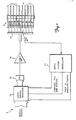
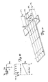
- FIG. 1 is a block diagram of a negative feed back transducer positioning system 8 according to the present invention.
- a stack of magnetically encodable disks is shown generally at 10.
- An electro-mechanical actuator (or E-block) 12 is used to position a servo transducer 14 and a plurality of data transducers 18 radially with respect to a servo disk 16 and data disks 17, respectively.
- the servo transducer is positioned over a desired track on the servo disk 16 where it is held while the data transducers 18, which are also connected to the E-block 12, perform read or write operations.
- the servo transducer 14 reads position information from servo disk 16 and provides position signals to a pre-amplifier 20 where it is amplified and provided to a servo position demodulator 22.
- the servo position demodulator 22 decodes the position information and presents it, in digital form, to a servo control processor 24.
- the servo control processor 24 compares the decoded position signal received from the servo position demodulator 22 with a desired position signal to determine a transducer position error.
- the transducer position error represents the difference between the actual position of the transducer 14, indicated by the decoded position signal, and the desired position indicated by a desired position signal.
- the servo control processor 24 then generates a position correction signal which is converted to an analog signal in digital-to-analog (D/A) converter 26 and applied to the E-block 12 through a power amplifier 28.
- the position correction signal causes the E-block 12 to move the transducers 14, 18 radially with respect to the disks 16, 17 in order to minimise the transducer position error.
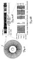
- One disk surface of the servo disk 16 is dedicated to contain servo tracks. This surface is shown in Figure 2.
- the servo position information in the servo tracks is not continuous but is condensed into evenly spaced sectors. This is known as a sectored servo system.
- Figure 3A is an enlarged portion of one servo sector on the servo disk 16.
- Figure 3B shows the format of servo information, represented by black and white bars, in one servo sector on the servo disk 16.
- the black and white bars represent oppositely magnetised areas on a surface coating of the servo disk 16.
- the oppositely magnetised areas are recorded close enough together so that the position signal generated by the servo transducer 14 is generally sinusoidal.
- Figure 3B shows that one servo sector contains several distinct fields.
- the fields include a phase locked oscillator/automatic gain control (PLO/AGC) synch field, a track identification (track ID) field, three position error sample (PES) fields and an index field.
- PLO/AGC phase locked oscillator/automatic gain control
- Track ID track identification
- PES position error sample
- Figure 3B also shows the magnetised areas for three tracks A, B and C on servo disk 16 where the outer radius and inner radius of the tracks is indicated.
- the direction of the servo transducer velocity and the track centre of each track is indicated by dashed arrows A, B and C, respectively.
- the sinusoidal position signal represents the magnetically encoded information shown in Figure 3B.
- Figure 4A illustrates the position signal generated by the servo transducer 14 as a function of five radial transducer positions along a single track (for example track B) on the servo disk 16 where position 3 represents the centre of the track.
- Positions 1 and 5 represent off centre positions where the centre of the servo transducer 14 is radially aligned with, and flying over the outer radius or inner radius of track B, respectively. If the servo transducer 14 were tracking along position 1, a position error equal to the radial distance between position 1 and position 3 would exist. Similarly, if transducer 14 were tracking along position 5, a position error equal to the radial distance between position 3 and position 5 would exist.
- Positions 2 and 4 also represent off centre positions. However, the off centre position error is not as large as the error associated with positions 1 and 5.
- Figure 4B shows the spatial relationship between the servo transducer 14, the magnetised areas of the servo disk 16, and each of the transducer positions 1 to 5.
- FIG. 4A shows that, as the servo transducer 14 flies over this region, its output position signal is a constant frequency, independent of the particular track over which it is flying and independent of radial position on the track.
- the information in this field is encoded in this way so that a phase locked oscillator in the servo position demodulator 22 can synchronise with the output of the servo transducer 14.
- the track ID number is encoded as a Gray code where only one bit changes from track to track.
- Each track ID bit is represented by one dibit cell.
- the amplitude of a dibit depends on the radial position of servo transducer 14. If the dibit amplitude exceeds a given threshold, in this embodiment one half the maximum possible amplitude, the dibit is decoded as a logic 1 in the servo position demodulator 22. Otherwise, it is decoded as a logic 0. Therefore, n bit cells define 2 n servo tracks on the disk.
- the magnetic information encoded on adjacent tracks is recorded 180° out of phase. This produces a chequer-board pattern of magnetisation.
- the magnetic information in the PES fields is also recorded plus or minus 90° out of phase with respect to the magnetic information encoded in the PLO/AGC synch field.
- the PES1 field is also called a normal field.
- the boundary between the magnetisation tracks in the normal field are arranged so that they lie on the centre line of the data tracks. Therefore, when the servo transducer 14 is over the normal field, as the servo transducer 14 moves radially further from the centre position 3 of track B, the amplitude of the position signal from the servo transducer 14 is larger. Similarly, as the servo transducer 14 moves radially closer to the centre position 3, the amplitude of the position signal is smaller.
- the PES2 field (also known as a quadrature field) is split in half.
- Half of the quadrature field (the PES2A field) lies on one side of the normal field and half (the PES2B field) lies on an opposite side of the normal field.
- the quadrature field is encoded with a magnetisation pattern which is identical to that of the normal field but which is radially off-set from it by half a track width. Therefore, when the servo transducer 14 is over the quadrature field, the position signal provided by the servo transducer 14 is at a maximum amplitude when the servo transducer 14 is flying over the track centre position 3 and at a minimum amplitude when it is flying over the off centre positions 1 and 5.
- the information read from the normal and quadrature fields is referred to as a position error sample.
- the normal and quadrature fields each produce a separate position error sample.
- the amplitude of the position signal provided by the servo transducer 14 representing the position error samples is a linear function of the distance of the centre of the servo transducer 14 from the track centre (position 3). This is shown theoretically in Figure 5.
- the servo transducer 14 is moving relative to the servo disk 16 in the direction indicated by arrow 30.
- the servo transducer 14 may be regarded as being composed of a set of read elements of differential width operating in parallel, whose output signals are added together or integrated to produce the total output voltage of the position signal from the servo transducer 14.
- the position signal from the servo transducer 14 is sinusoidal. Any fringing field effect is neglected. Since the magnetic pattern in the servo sector was originally written 180° out of phase for adjacent tracks, the signal produced by a differential read element, dy , will be defined as either plus or minus Vm Cos (wt).
- the total output voltage from the servo transducer 14 depends on how many differential read elements produce +Vm Cos (wt) and how many produce -Vm Cos (wt).
- d the distance from the centre of the servo transducer 14 to the nearest data track centre (a boundary between the +Vm Cos (wt) and -Vm Cos (wt) regions in the PES1 field).
- the distance d may be positive (towards the inner radius) or negative (towards the outer radius).
- each read element dy contributes a fraction equal to dy/b towards the total output voltage provided by the servo transducer 14.
- the amplitude of the position signal of the servo transducer 14 does not change linearly across the full track width. It becomes non-linear at some point near the outside twenty five percent of the track, depending on the physical dimensions of the servo transducer 14 and its relationship to the dimensions of the written magnetised pattern.
- FIG. 4A shows the quadrature relationship between the PES2A and the PES2B fields and the PES1 field.
- the amplitude of the position signal provided by the servo transducer 14 in the PES2 field is at a maximum, and therefore in a non-linear region when the amplitude in the PES1 field is at a minimum (and therefore in a linear region), and vice versa.
- either the quadrature or the normal field is always in a linear region and there is always a linear relationship between the position signal corresponding to one of the PES fields (PES1 or PES2) and the distance between the centre of the servo transducer 14 and the track centre (the off track error) no matter where the servo transducer 14 is positioned across the radial width of a track on the servo disk 16.
- PES1 or PES2 the position signal corresponding to one of the PES fields
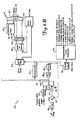
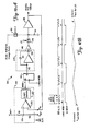
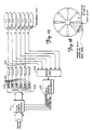
- FIG. 6 is a more detailed block diagram of the servo position demodulator 22 which decodes position information represented by the analog position signal from the servo transducer 14.
- the position signal from the servo transducer 14 is applied to a filter 32 where it is filtered to remove high frequency noise.
- the filtered signal is then applied to an automatic gain control (AGC) loop 34 ( Figure 6B).
- AGC automatic gain control
- the AGC loop 34 is comprised of a voltage controlled amplifier 36, an analog multiplier 38, a voltage-to-current converter 40 and a current summing junction 42.
- An analog switch 44 and a capacitor 46 allow the AGC loop 34 to be configured in an acquire mode or a hold mode (explained later).
- An overall reference for the automatic gain controlled amplitude is provided through a filter 48 by a micro-processor (not shown).
- the overall reference determines the final position gain in volts per micro-inch.
- the AGC loop 34 is initially calibrated by the micro-processor and compensates for changes in input signal amplitude due to changes in track radius, flying height and other media properties.
- an automatic gain controlled (AGC'd) analog signal from the AGC loop 34 is transmitted to a voltage comparator 50 which generates serial digital data corresponding to the AGC'd analog signal.
- the comparator 50 provides the serial digital data to a synch detector circuit 52 and a serial-to-parallel shift register 54.
- the synch detector circuit 52 identifies the start of a servo sector and enables a programmable event generator (PEG) 56.
- the programmable event generator 56 produces timing and window logic signals required for position demodulation in the servo position demodulator 22.
- the comparator 50 decodes track ID dibits as either logic 1 or logic 0 depending on their amplitude.
- the comparator 50 has a threshold of one half the maximum automatic gain controlled amplitude.
- the serial digital track ID bits are shifted into the shift register 54 to produce a parallel track ID word.
- This track ID word is in Gray code and is converted to a binary track ID word by combinational logic 58.
- the binary track ID word is latched in a latch 60 and provided to track ID correction logic 62 which will be explained in more detail later.
- the output of the correction logic 62 is a track identification signal or absolute position signal which identifies the particular track over which the servo transducer 14 is flying.
- the shift register 54 is also used to provide index information to an index pattern detector 64 which is not important to an understanding of the present invention and so will not be discussed further.
- the AGC'd analog signal from the AGC loop 34 is also transmitted to a phase locked oscillator loop (PLO loop) 66 ( Figure 6A).
- the PLO loop 66 comprises an analog switch 68, a phase comparator/multiplier 70, a voltage-to-current conververter (charge pump) 72, which includes a balance circuit 74 for balancing the voltage-to-current converter 72 once per servo sector so that there is zero current output for zero voltage input, an analog switch 76, a filter 78, a voltage controlled oscillator 80 and a clock generator 82.
- the PLO loop 66 locks onto the phase and frequency of the AGC'd analog signal provided by the AGC loop 34.
- the analog switch 76 is opened allowing the PLO loop 66 to open.
- the signal provided to the voltage controlled oscillator 80 is then held constant. Hence, a constant frequency results at the output of the voltage controlled oscillator 80. Therefore, the frequency of a digital feed back signal 120 from the clock generator 82 is also constant.
- the output of voltage to the voltage-to-current converter 72 is also provided to a PES capacitor 84 through an analog switch 86. Voltage is integrated on the capacitor 84 during synchronous demodulation of PES fields PES1, PES2A and PES2B. This voltage is applied through a buffer 88 to an analog-to-digital (A/D) converter 90.
- the output of the A/D converter 90 is provided to a composite PES generator logic 92.
- the composite PES generator logic 92 comprises latches 94, 96, a digital adder 98, multiplexers 100 and 102, multiplexer control logic 104, a switchable inverter 106 and inverter control logic 108.
- the output of the composite PES generator logic 92 is a composite PES word or fine position off track error which represents the distance that the servo transducer 14 is tracking from the track centre.
- the digital position word defines the radial position of the servo transducer 14 on the servo disk 16 in a continuous fashion down to approximately one or two micro-inches of quantisation.
- the PES capacitor 84 is also selectively connected to a DC null loop 110 comprised of the A/D converter 90, a one-bit latch 112, and integrator 114, a buffer 116, an analog switch 118 and the buffer 88.
- the DC null loop 110 drives the initial voltage on the PES capacitor 84 to a mid-point between upper and lower reference voltages applied to an internal resistor ladder in the A/D converter 90.
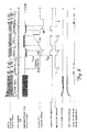
- Figure 7 is a timing diagram which shows the relationship between logic control signals generated by the programmable event generator 56, the analog position signal and the PES capacitor voltage as the servo transducer 14 moves over one servo sector.
- Figure 8 is a timing diagram showing the relationship between various signals related to the synchronous demodulation of the fine position information in the servo position demodulator 22 as the servo transducer 14 moves along one servo sector.
- the programmable event generator 56 closes the switch 44 to close the AGC loop 34.
- the AGC loop 34 acquires the proper gain so that the amplitude of the analog position signal is compensated for amplitude changes caused by changes in track radius, transducer flying height, and other media properties.
- the programmable event generator 56 closes the analog switches 68, 76 to close the PLO loop 66.
- the voltage control oscillator 80 locks onto the phase and frequency of the AGC'd analog signal provided by the AGC loop 34.
- the PLO loop 66 uses the digital feed back signal 120 which locks in at a 90° phase shift from the AGC'd analog signal provided by the AGC loop 34.
- the analog switches 44, 76 are opened and both the AGC loop 34 and the PLO loop 66 enter a hold mode. While in the hold mode the amplification in the AGC loop 34 and the phase and frequency of the feed back signal 120 in the PLO loop 66 remain constant.
- the servo transducer 14 passes over the track ID field in the servo sector.
- the serial digital track ID bits are formed by the comparator 50 and shifted into the shift register 54.
- the Gray code track ID bits are converted into a binary code by the converter 58 and latched into the latch 60.
- the servo transducer 14 enters the PES fields in the servo sector.
- the switch 68 is closed applying the analog position signal to the phase comparator/multiplier 70 while the switch 76 remains open.
- the feed back signal 120 is multiplied by the analog position signal in the phase comparator/multiplier 70. Since the information in the PLO/AGC synch field is recorded 90° out of phase with the information in the PES fields, and since the feed back signal 120 is held with a 90° phase shift, the multiplication performed at the phase comparator/multiplier 70 produces a full wave rectification of the analog position signal. This is shown by plot C in Figure 8.
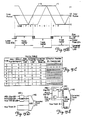
- Figure 9A illustrates the output of the phase comparator/multiplier 70 for the five radial positions of the servo transducer 14 which were described earlier with reference to Figure 4A.
- Figure 9B shows the spatial relationship between the centre of the servo transducer 14 and the centre of track B in radial transducer positions 1 to 5.
- the amplitude of output signal of the phase comparator/multiplier 70 is proportional to the distance between the centre of the servo transducer 14 and the centre of track B.
- the polarity of the DC component of the signal indicates the direction of the off-set.
- Figure 10 illustrates the general case where n cycles of current are integrated to produce the analog voltage on the PES capacitor 84 corresponding to one PES field.
- the final voltage on the PES capacitor 84 is also proportional to the number, n , of cycles integrated.
- n cycles are integrated and the A/D converter 90 converts the analog voltage on the PES capacitor 84 into a digital signal which is latched in the latch 94.
- first n/2 cycles for the PES2A field
- the A/D converter 90 converts the value to a digital signal which is latched in the latch 96.
- another n/2 cycles for the PES2B field
- another A/D conversion is made by the A/D converter 90.
- the resulting digital signal is provided to the adder 98 where the digital signal representing the PES2A field is added to it to produce a full PES2 position sample.
- the number of cycles, n chosen should be high enough to achieve the averaging of possible media defects over several cycles. However, it must not be so high as to produce an overly long servo sector since the length of the servo sector limits the maximum radial velocity of the servo transducer 14.
- the final voltage on the PES capacitor 84 is also proportional to the capacitance of the PES capacitor 84. Note that the same PES capacitor 84 is used to produce the analog PES voltage for both the PES1 and PES2 position samples. After the A/D conversion of the final ramp voltage of a PES measurement, the digital result is latched so the analog voltage on the PES capacitor 84 can be re-set, and the same PES capacitor 84 can be reused for the next PES measurement. This eliminates the possibility of position error due to capacitance mis-match which would result if two or more capacitors were used to produce the analog PES voltage. Using only one capacitor to integrate the position signal for both the quadrature and normal fields increases the accuracy with which the servo transducer 14 follows the track.
- A/D converter 90 is required to convert the analog PES voltages to digital signals. This lowers the overall cost of the servo position demodulator 22. Also, the A/D conversion made by the A/D converter 90 is made early in the processing chain in the servo position demodulator 22. The addition of the PES2A and PES2B position samples and the formation of the composite PES signal all take place in the digital domain. This minimises the amount of analog circuitry and associated errors such as off-set errors, gain errors, linearity errors and variation with temperature. Additionally, all of the digital circuits can be fabricated into one compact integrated circuit to save space.
- FIG. 12A shows the DC null loop 110 in greater detail and Figure 12B is a timing diagram showing the relationship between signals occurring in the DC null loop 110.
- programmable event generator 56 generates a signal on an output L7 causing the A/D converter 90 to perform a first A/D conversion.
- the A/D converter 90 comprises a resistor ladder connected between reference voltages VREF+ and VREF-, 15 comparators including a most significant bit comparator 130, and a logic decode 132 which decodes a most significant bit of the A/D converter 90.
- Resistors R1 and R2 which represent the resistor ladder condensed into two resistors, act as a voltage divider creating an internal voltage mid-point Vmidref at a node 129.
- the most significant bit of the A/D converter 90 is decoded and latched into the one-bit latch 112.
- the value of the latched most significant bit depends on whether signal Vin is greater or less than the internal voltage Vmidref at the node 129.
- the gain in the AGC loop 34 is set so that the A/D converter 90 full digital scale corresponds to one half of a servo track.
- the internal voltage Vmidref corresponds to the track centre or zero position error.
- the latched, most significant bit is applied to the integrator 114.
- the output of the integrator 114 an external voltage Vmidref at a node 134, is driven towards the value of the internal voltage Vmidref.
- the gain through the integrator 114 is chosen so that the external voltage Vmidref just crosses the internal voltage Vmidref before the next servo sector. This is shown in Figure 12B.
- the peak to peak limits of the external voltage Vmidref must be kept much lower than the analog value of a least significant bit of the A/D converter 90. This keeps the initial voltage on the PES capacitor 84 as close as possible to the exact centre of the digital scale.
- the switch 118 is opened and the A/D converter 90 is available for conversions 2, 3 and 4 which are conversions for the position samples read from the PES2A, PES1 and PES2B fields. Between position samples, the switch 118 closes to re-set the PES capacitor 84 to the external voltage Vmidref. Hence, the DC null loop 110 compensates for static or time variable DC off-sets in the buffer 88 and the switch 118, which are inside the DC null loop 110. This increases the track following accuracy of the servo transducer 14.
- the output of voltage to the voltage-to-current converter 72 is connected to the PES capacitor 84 through the analog switch 86 and the PES capacitor voltage ramps up or down as shown in Figure 8.
- the difference between the final voltage on the PES capacitor 84 and the initial voltage is proportional to the distance of the centre of the servo transducer 14 from the track centre.
- Figure 13A shows the concept of a total position word.
- the track ID number and the digital value representing the PES field samples are combined to define the radial position of the servo transducer 14 anywhere on the servo disk 16.
- the track ID number defines the track and the PES samples define the position within the track.
- the servo transducer 14 flies over the track on the servo disk 16, it moves over the track ID field prior to moving over the PES fields. Hence, the track ID information is decoded earlier in time than information read from the PES fields. Since the information read from the PES fields is read later in time, it is more recent and, hence, more accurate position information than that read from the track ID field.
- the servo transducer 14 is moving radially, it has a slanted trajectory across the servo sector. Therefore, it may enter the servo sector in the track ID field of one track but cross a boundary between tracks and exit the servo sector from the PES field of the next track.
- correction logic 140 (shown in Figures 6B and 13D) is used to detect when it is necessary to correct the track ID so that it corresponds to the track number from which the PES field samples were read.
- Figure 13B is a graph of the amplitude of the position signal corresponding to the PES fields, in 2's complement form, as it relates to the least significant bit in the track ID signal.
- Figure 13B also shows a corrected least significant bit in the track ID signal.
- Trace A represents the 2's complement form of the amplitude of the position signal corresponding to the PES1 field.
- Trace B represents the 2's complement amplitude corresponding to the PES2 field (the PES2A field + the PES2B field).
- the truth table shown in Figure 13C defines the conditions where the track ID information is not correlated with the PES field information and the correction word which is required.
- the correction logic 140 forms a correction number of ⁇ 1 which is added to the track ID in an adder 142. For all other cases, the number 0 is added to the track ID.
- Figure 13E shows the correction logic 140 in more detail. It should be noted that the addition of the correction word to the track ID could also be accomplished by software in the servo control processor 24.
- This correlation allows the servo control processor 24 to use bits of the digital composite PES signal along with a track ID to determine very precisely the position and velocity of the servo transducer 14 even at high radial velocities.
- the increased accuracy of the total position signal at high radial velocities helps to minimise both the time and power required for performing a track seek operation.
- this correlation permits a smoother settling of the servo transducer on a track.
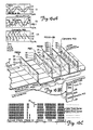
- Figure 14A is an imaginary tracing of digitised final voltage values of the analog PES ramps generated at the PES capacitor 84 for all radial positions of the servo transducer 14 across four adjacent tracks in a servo-on-data system. These imaginary tracings are called track crossing plots. The digital values are in 2's complement form and the point at which the track crossing plot for the PES1 field crosses 00 hex represents the track centre.
- Graph G1 in Figure 14A shows the three track crossing plots condensed onto a single plane. Since there are equal number of cycles in the PES2A field and the PES2B field, their corresponding track crossing plots coincide. However, since the integration measurement time period for the PES2A and PES2B fields is only one half that of the PES1 field, the slope of the PES2A and PES2B track crossing plots in volts per micro-inch is only one half that of the PES1 track crossing plot.
- the PES2A position sample is added to the PES2B position sample to produce the total PES2 or quadrature sample.
- One hardware implementation to perform this addition was discussed with reference to Figure 6. This addition can also be performed graphically.
- Graph G2 in Figure 14A shows that the addition of the PES2A and PES2B track crossing plots produces a new track crossing plot which has the same slope as the PES1 track crossing plot.
- the PES1 and PES2 track crossing plots shown in graph G2 in Figure 14A are the inputs to the composite PES generator 92. However, at only one radial position along the servo disk 16, only one of the two plots is in a region where the PES amplitude is changing linearly with transducer position. There are eight distinct regions labelled a to h which repeat across the track.
- the composite PES generator 92 determines over which of the eight regions the servo transducer 14 is flying. The composite PES generator 92 then creates a composite position error sample output which is the standardised form of position error sample required by the servo control processor 24.
- the composite PES generator 92 accomplishes this by inverting the slope or changing the sign bit of the PES1 or PES2 track crossing plots when necessary, and combining the linear portions to create the desired composite PES track crossing plot shown in graph G3 in Figure 14A.
- Figures 15A to 15C show how the addition of the PES2A and PES2B position samples helps to compensate for high radial velocity of the servo transducer 14.
- a slanted trajectory of the servo transducer 14 is shown by arrow 150 in Figure 15A. This slanted trajectory causes an apparent shift in the PES1 and PES2B track crossing plots as shown in Figure 15B.
- the actual value of the PES2A and PES2B fields is shown by a solid line and the ideal value is shown by a dashed line.
- a new track crossing plot, PES2C is formed as shown in Figure 15C.
- the PES2C track crossing plot has the correct orientation with respect to the PES1 track crossing plot.
- This invention is not limited for use in dedicated servo systems such as the one shown in Figure 1.
- This invention may also be used in hydrid servo configurations.
- a hybrid system has a dedicated surface containing servo sectors and other disks which contain one or more similar servo sectors per revolution which are decoded for data transducer thermal off-set compensation. Since a common servo sector pattern is used, through the use of time multiplexing only one servo position demodulator is needed.
- the present invention may also be used in servo-on-data type servo systems where each disk surface has servo sectors.
- customer data is written between the write protected servo sectors. Any head actively reading or writing customer data is also acting as its own track following error sensor. This increases track following precision and allows higher track densities to be achieved.
- FIG. 17 Another servo system configuration in which this invention may be used is one having multiple independent actuators 200. This is shown in Figure 17. If a multiple actuator system contains n actuators 200 and corresponding amplifiers 202, the servo sectors under servo transducers 204 on adjacent actuators are staggered by 1/n of the distance between servo sectors on one disk. The servo sectors for adjacent actuators must not overlap. This is illustrated in Figure 18. In this type of system, a multiplexer 205 continuously cycles through the servo sectors of the actuators 200.
- the servo sector format described in this invention may be used with linear or rotary actuators.
- FIG. 16A to 16C A method for creating the composite PES output for a dedicated servo system is shown in Figures 16A to 16C.
- the servo track width can be twice the data track width.
- the servo transducer 14 is then twice as wide as a data transducer 18. This can help minimise non-linear effects of fringing fields read by the edges of the servo transducer 14. It can also improve the signal to noise ratio of the track ID bits.
- the composite PES generator 92 merely inverts the slope of the d , e , f and g segments.
- the servo track centres are derived alternately from PES1 and PES2 position samples.
- the transducer is used for both serving and reading and writing customer data.
- the servo track and data track are automatically the same width.
- the composite PES track crossing plot is then formed as shown in graph G3 in Figure 14A. Slope segments a and d are re-positioned to extend the linearity of the b and c segments. This produces a linear PES plot across the full track width. Similarly, the e and h segments extend the linearity of the f and g segments.
- the track centre is always derived from the PES1 position sample.
- One advantageous feature of this method is that the composite PES field has one more bit of quantisation than the A/D converter 90 used in the servo position demodulator 22.
- the quadrature field is split in half. Half of the quadrature field lies on one side of the normal field and half lies on the opposite side of the normal field.
Landscapes
- Engineering & Computer Science (AREA)
- Signal Processing (AREA)
- Moving Of The Head To Find And Align With The Track (AREA)
- Moving Of Head For Track Selection And Changing (AREA)
- Signal Processing For Digital Recording And Reproducing (AREA)
Applications Claiming Priority (2)
| Application Number | Priority Date | Filing Date | Title |
|---|---|---|---|
| US41505489A | 1989-09-29 | 1989-09-29 | |
| US415054 | 1989-09-29 |
Publications (2)
| Publication Number | Publication Date |
|---|---|
| EP0420438A1 true EP0420438A1 (fr) | 1991-04-03 |
| EP0420438B1 EP0420438B1 (fr) | 1996-03-13 |
Family
ID=23644179
Family Applications (1)
| Application Number | Title | Priority Date | Filing Date |
|---|---|---|---|
| EP19900309906 Expired - Lifetime EP0420438B1 (fr) | 1989-09-29 | 1990-09-11 | Méthode et appareil pour détecter l'erreur de positionnement d'un transducteur |
Country Status (5)
| Country | Link |
|---|---|
| EP (1) | EP0420438B1 (fr) |
| JP (1) | JPH0831261B2 (fr) |
| DE (1) | DE69025840T2 (fr) |
| PT (1) | PT95441A (fr) |
| SG (1) | SG47965A1 (fr) |
Citations (3)
| Publication number | Priority date | Publication date | Assignee | Title |
|---|---|---|---|---|
| EP0094314A1 (fr) * | 1982-05-10 | 1983-11-16 | Digital Equipment Corporation | Système asservi de positionnement à données d'asservissement continuées et intercalées pour mémoire à disques |
| US4590526A (en) * | 1983-11-01 | 1986-05-20 | Amcodyne Incorporated | Method and apparatus for controlling head movement relative to a disk in an embedded servo system |
| EP0332056A1 (fr) * | 1988-03-07 | 1989-09-13 | Siemens Aktiengesellschaft | Dispositif de stockage à disques magnétiques avec des informations de commande de position, enregistrées sur une surface servo séparée |
Family Cites Families (4)
| Publication number | Priority date | Publication date | Assignee | Title |
|---|---|---|---|---|
| US4208679A (en) * | 1978-02-28 | 1980-06-17 | Digital Equipment Corporation | Transducer positioning system for rotating disk drive units |
| US4472750A (en) * | 1981-07-02 | 1984-09-18 | Irwin Magnetic Systems, Inc. | Data record with pre-recorded transducer positioning signals, and system for utilizing same |
| DE3326724A1 (de) * | 1983-07-25 | 1985-02-07 | Boehringer Ingelheim KG, 6507 Ingelheim | In 1-stellung substituierte 4-hydroxymethyl-pyrrolidinone, verfahren zu ihrer herstellung, pharmazeutische zusammensetzungen und zwischenprodukte |
| US4823212A (en) * | 1986-11-26 | 1989-04-18 | Hewlett-Packard Company | Sampled servo code format and system for a disc drive |
-
1990
- 1990-09-11 EP EP19900309906 patent/EP0420438B1/fr not_active Expired - Lifetime
- 1990-09-11 DE DE1990625840 patent/DE69025840T2/de not_active Expired - Fee Related
- 1990-09-11 SG SG1996005728A patent/SG47965A1/en unknown
- 1990-09-27 PT PT9544190A patent/PT95441A/pt not_active Application Discontinuation
- 1990-09-28 JP JP2260339A patent/JPH0831261B2/ja not_active Expired - Lifetime
Patent Citations (3)
| Publication number | Priority date | Publication date | Assignee | Title |
|---|---|---|---|---|
| EP0094314A1 (fr) * | 1982-05-10 | 1983-11-16 | Digital Equipment Corporation | Système asservi de positionnement à données d'asservissement continuées et intercalées pour mémoire à disques |
| US4590526A (en) * | 1983-11-01 | 1986-05-20 | Amcodyne Incorporated | Method and apparatus for controlling head movement relative to a disk in an embedded servo system |
| EP0332056A1 (fr) * | 1988-03-07 | 1989-09-13 | Siemens Aktiengesellschaft | Dispositif de stockage à disques magnétiques avec des informations de commande de position, enregistrées sur une surface servo séparée |
Non-Patent Citations (1)
| Title |
|---|
| IBM TECHNICAL DISCLOSURE BULLETIN. vol. 22, no. 12, May 1980, NEW YORK US pages 5436 - 5438; liu: "quad-burst servo pattern" * |
Also Published As
| Publication number | Publication date |
|---|---|
| EP0420438B1 (fr) | 1996-03-13 |
| SG47965A1 (en) | 1998-04-17 |
| JPH0831261B2 (ja) | 1996-03-27 |
| PT95441A (pt) | 1992-05-29 |
| DE69025840T2 (de) | 1996-10-17 |
| DE69025840D1 (de) | 1996-04-18 |
| JPH03205664A (ja) | 1991-09-09 |
Similar Documents
| Publication | Publication Date | Title |
|---|---|---|
| EP0420439B1 (fr) | Méthode et appareil pour déterminer la position d'un transducteur | |
| EP0420440B1 (fr) | Méthode et système pour démoduler les signaux de position d'un transducteur | |
| HK1002047B (en) | Method of and apparatus for determining the position of a transducer | |
| US5182682A (en) | Sectored servo disk formatting | |
| US4578723A (en) | Head positioning system with automatic gain control | |
| EP0097209B1 (fr) | Disque magnétique d'enregistrement et pile de disques utilisant un secteur d'asservissement pour positionner la tête | |
| KR100570558B1 (ko) | 통합된 판독 및 서보채널을 가진 동기식 디지털 복조기 | |
| EP0471314B1 (fr) | Servosystème à positionner d'une tête de balayage de disques | |
| EP0243729B1 (fr) | Méthode et appareil pour éliminer un décalage apparent dans un code d'asservissement dans l'entraînement d'un disque magnétique | |
| KR950015341A (ko) | 디스크 드라이버와 디스크 헤드 위치 제어 시스템 및 트랙 코드 어드레스 버스트 패턴 감지 방법 | |
| US4782404A (en) | Positioning system for a disc drive using a stepper motor | |
| JPS6292221A (ja) | 垂直磁気記録ヘツド位置サ−ボ制御装置 | |
| EP0420438B1 (fr) | Méthode et appareil pour détecter l'erreur de positionnement d'un transducteur | |
| HK1013172B (en) | A method of and system for demodulating position information signals provided by a transducer | |
| US4418368A (en) | Method and apparatus for positioning a transducer using embedded servo track encoding | |
| US5812339A (en) | Method and apparatus for controlling the position of an object along a radial direction of a rotating body | |
| WO1999006992A9 (fr) | Procede et dispositif permettant d'augmenter la vitesse d'echantillonnage d'une unite de disques avec surchage systeme reduite | |
| KR980011321A (ko) | 자기기억장치의 리드신호 편차 보상방법 | |
| Rose | A high performance embedded servo system | |
| JPS61236016A (ja) | 磁気デイスク装置 | |
| JPS6148132A (ja) | 光デジタルデ−タの記録方法 | |
| JPH0231388A (ja) | デジタルサーボ装置 |
Legal Events
| Date | Code | Title | Description |
|---|---|---|---|
| PUAI | Public reference made under article 153(3) epc to a published international application that has entered the european phase |
Free format text: ORIGINAL CODE: 0009012 |
|
| AK | Designated contracting states |
Kind code of ref document: A1 Designated state(s): DE FR GB IT NL |
|
| 17P | Request for examination filed |
Effective date: 19910702 |
|
| 17Q | First examination report despatched |
Effective date: 19931227 |
|
| GRAH | Despatch of communication of intention to grant a patent |
Free format text: ORIGINAL CODE: EPIDOS IGRA |
|
| GRAA | (expected) grant |
Free format text: ORIGINAL CODE: 0009210 |
|
| AK | Designated contracting states |
Kind code of ref document: B1 Designated state(s): DE FR GB IT NL |
|
| REF | Corresponds to: |
Ref document number: 69025840 Country of ref document: DE Date of ref document: 19960418 |
|
| ET | Fr: translation filed | ||
| ITF | It: translation for a ep patent filed | ||
| PGFP | Annual fee paid to national office [announced via postgrant information from national office to epo] |
Ref country code: FR Payment date: 19960822 Year of fee payment: 7 |
|
| PGFP | Annual fee paid to national office [announced via postgrant information from national office to epo] |
Ref country code: NL Payment date: 19960910 Year of fee payment: 7 |
|
| PLBE | No opposition filed within time limit |
Free format text: ORIGINAL CODE: 0009261 |
|
| STAA | Information on the status of an ep patent application or granted ep patent |
Free format text: STATUS: NO OPPOSITION FILED WITHIN TIME LIMIT |
|
| 26N | No opposition filed | ||
| PG25 | Lapsed in a contracting state [announced via postgrant information from national office to epo] |
Ref country code: FR Free format text: THE PATENT HAS BEEN ANNULLED BY A DECISION OF A NATIONAL AUTHORITY Effective date: 19970930 |
|
| PG25 | Lapsed in a contracting state [announced via postgrant information from national office to epo] |
Ref country code: NL Free format text: LAPSE BECAUSE OF NON-PAYMENT OF DUE FEES Effective date: 19980401 |
|
| NLV4 | Nl: lapsed or anulled due to non-payment of the annual fee |
Effective date: 19980401 |
|
| REG | Reference to a national code |
Ref country code: FR Ref legal event code: ST |
|
| PGFP | Annual fee paid to national office [announced via postgrant information from national office to epo] |
Ref country code: GB Payment date: 20000804 Year of fee payment: 11 |
|
| PGFP | Annual fee paid to national office [announced via postgrant information from national office to epo] |
Ref country code: DE Payment date: 20000825 Year of fee payment: 11 |
|
| REG | Reference to a national code |
Ref country code: GB Ref legal event code: 732E |
|
| PG25 | Lapsed in a contracting state [announced via postgrant information from national office to epo] |
Ref country code: GB Free format text: LAPSE BECAUSE OF NON-PAYMENT OF DUE FEES Effective date: 20010911 |
|
| GBPC | Gb: european patent ceased through non-payment of renewal fee |
Effective date: 20010911 |
|
| PG25 | Lapsed in a contracting state [announced via postgrant information from national office to epo] |
Ref country code: DE Free format text: LAPSE BECAUSE OF NON-PAYMENT OF DUE FEES Effective date: 20020501 |
|
| PG25 | Lapsed in a contracting state [announced via postgrant information from national office to epo] |
Ref country code: IT Free format text: LAPSE BECAUSE OF NON-PAYMENT OF DUE FEES Effective date: 20050911 |