EP0420462A2 - Katalytischer Konverter - Google Patents
Katalytischer Konverter Download PDFInfo
- Publication number
- EP0420462A2 EP0420462A2 EP90310110A EP90310110A EP0420462A2 EP 0420462 A2 EP0420462 A2 EP 0420462A2 EP 90310110 A EP90310110 A EP 90310110A EP 90310110 A EP90310110 A EP 90310110A EP 0420462 A2 EP0420462 A2 EP 0420462A2
- Authority
- EP
- European Patent Office
- Prior art keywords
- converter
- passages
- housing
- inlet
- gas
- Prior art date
- Legal status (The legal status is an assumption and is not a legal conclusion. Google has not performed a legal analysis and makes no representation as to the accuracy of the status listed.)
- Withdrawn
Links
Images


Classifications
-
- F—MECHANICAL ENGINEERING; LIGHTING; HEATING; WEAPONS; BLASTING
- F01—MACHINES OR ENGINES IN GENERAL; ENGINE PLANTS IN GENERAL; STEAM ENGINES
- F01N—GAS-FLOW SILENCERS OR EXHAUST APPARATUS FOR MACHINES OR ENGINES IN GENERAL; GAS-FLOW SILENCERS OR EXHAUST APPARATUS FOR INTERNAL-COMBUSTION ENGINES
- F01N3/00—Exhaust or silencing apparatus having means for purifying, rendering innocuous, or otherwise treating exhaust
- F01N3/08—Exhaust or silencing apparatus having means for purifying, rendering innocuous, or otherwise treating exhaust for rendering innocuous
- F01N3/10—Exhaust or silencing apparatus having means for purifying, rendering innocuous, or otherwise treating exhaust for rendering innocuous by thermal or catalytic conversion of noxious components of exhaust
- F01N3/24—Exhaust or silencing apparatus having means for purifying, rendering innocuous, or otherwise treating exhaust for rendering innocuous by thermal or catalytic conversion of noxious components of exhaust characterised by constructional aspects of converting apparatus
- F01N3/28—Construction of catalytic reactors
- F01N3/2892—Exhaust flow directors or the like, e.g. upstream of catalytic device
-
- F—MECHANICAL ENGINEERING; LIGHTING; HEATING; WEAPONS; BLASTING
- F01—MACHINES OR ENGINES IN GENERAL; ENGINE PLANTS IN GENERAL; STEAM ENGINES
- F01N—GAS-FLOW SILENCERS OR EXHAUST APPARATUS FOR MACHINES OR ENGINES IN GENERAL; GAS-FLOW SILENCERS OR EXHAUST APPARATUS FOR INTERNAL-COMBUSTION ENGINES
- F01N3/00—Exhaust or silencing apparatus having means for purifying, rendering innocuous, or otherwise treating exhaust
- F01N3/08—Exhaust or silencing apparatus having means for purifying, rendering innocuous, or otherwise treating exhaust for rendering innocuous
- F01N3/10—Exhaust or silencing apparatus having means for purifying, rendering innocuous, or otherwise treating exhaust for rendering innocuous by thermal or catalytic conversion of noxious components of exhaust
- F01N3/18—Exhaust or silencing apparatus having means for purifying, rendering innocuous, or otherwise treating exhaust for rendering innocuous by thermal or catalytic conversion of noxious components of exhaust characterised by methods of operation; Control
- F01N3/20—Exhaust or silencing apparatus having means for purifying, rendering innocuous, or otherwise treating exhaust for rendering innocuous by thermal or catalytic conversion of noxious components of exhaust characterised by methods of operation; Control specially adapted for catalytic conversion
- F01N3/2053—By-passing catalytic reactors, e.g. to prevent overheating
-
- F—MECHANICAL ENGINEERING; LIGHTING; HEATING; WEAPONS; BLASTING
- F01—MACHINES OR ENGINES IN GENERAL; ENGINE PLANTS IN GENERAL; STEAM ENGINES
- F01N—GAS-FLOW SILENCERS OR EXHAUST APPARATUS FOR MACHINES OR ENGINES IN GENERAL; GAS-FLOW SILENCERS OR EXHAUST APPARATUS FOR INTERNAL-COMBUSTION ENGINES
- F01N2470/00—Structure or shape of exhaust gas passages, pipes or tubes
- F01N2470/18—Structure or shape of exhaust gas passages, pipes or tubes the axis of inlet or outlet tubes being other than the longitudinal axis of apparatus
Definitions
- the invention relates to a catalytic converter for use in an exhaust system, particularly but not exclusively for a motor vehicle.
- Catalytic converters are in use in the exhaust systems of motor vehicles to reduce the release of obnoxious by-products of combustion into the atmosphere.
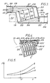
- Fig.1 of the accompanying drawings is a diagrammatic cross-section through a known converter in common use on vehicles.
- the converter comprises a housing 1 defining an entry section 2 for exhaust gases, a catalyst section 3 and an entry section 4.
- the catalyst section 3 houses two matrices 4, 5 each comprising a ceramic or metallic substrate having a plurality of longitudinally extending passages 6 coated with a catalyst material, e.g., platinum, and which are open at end surfaces 7, 8 of the matrices to define inlets and outlets 7a, 8a respectively.
- a catalyst material e.g., platinum
- the housing 1 has a flange 10 at its inlet end for attachment to an exhaust pipe (not shown) and is widened at 11 to form the entry section 2.
- a similar arrangement is provided at the opposite end of the housing to enable the housing to be attached by means of a flange 12 to a tail pipe or silencer of the exhaust system.
- Catalytic action is dependent upon the length of time which the exhaust gases spend passing through the matrices. As the flow is substantially of an in-line type, the gases tend to flow very quickly through the matrices and, therefore, it is necessary to provide long passages to provide sufficient catalytic action and to allow for attrition of the catalytic material over an extended service life. Normally, that is achieved by arranging two matrices in tandem as shown. However that arrangement tends to create a high back pressure which, is undesirable.
- the temperature of the catalyst section of the converter be sufficiently high.
- the known converter shown in Fig.1 is ineffective for the first one to two minutes and allows critical amounts of pollutants to pass straight through the catalyst section 3 into the atmosphere.
- the time taken for the catalyst section to heat up sufficiently is known as the "light-up" time.
- An object of the present invention is to provide and improved catalytic converter in which the above problems are substantially reduced.
- a catalytic converter comprising a housing having an entry duct defining a housing inlet for a stream of incoming exhaust gas, a catalyst section containing a matrix comprising catalyst material and having a plurality of longitudinally extending passages through which gas from the entry duct may pass and an exit duct for receiving gases from the passages and defining a housing outlet, the passages and the direction of gas flow through the entry duct being oblique relative to each other.
- the passages may be perpendicular to the end surfaces of the matrix or may be angled towards the direction of flow from the inlet.
- the entry duct narrows from a gas entry end towards an opposite end. In that way, the incoming gas is directed towards the passages in the matrix as it moves through the entry duct and turbulence is reduced.
- the entry duct is preferably defined in part between an end surface of the matrix, in which inlets for the passages are defined, and an opposite surface of the housing.
- the aforesaid two surfaces are preferabaly inclined relative to each other.
- an arrangement according to the invention provides a very large number of relatively short passages in the matrix which results in a back pressure which is significantly less than that which occurs with the known catalytic converter. Therefore, a catalytic coverter in accordance with the present invention will absorb less engine power than the known catalytic converter.
- the dimensions and shape of the housing can be arranged to suit vehicle installations where the known converter can be installed only with extreme difficulty or with compromises to the design and operational requirements of the converter or of other parts of the vehicle.
- the direction of gas flow through the exit duct is also oblique to the passages and the exit duct may widen towards the outlet.
- the exit duct may be formed in a similar manner to the entry duct and may, therefore, be defined in part between an end surface of the matrix in which the outlets for the passages are defined and between an opposite surface of the housing. Preferably, the two surfaces are inclined relative to each other.
- the housing may be arranged so that the housing inlet and housing outlet are substantially in-line. In that way, gas will flow substantially in the same direction therethrough.
- the housing inlet and the housing outlet may be offset relative to each other in a transverse sense. Such an arrangement may be useful where a projection on the vehicle e.g., a gear selector linkage needs to be accommodated alongside either the housing inlet or the housing outlet. In such a case, the projection may lie in a space provided by the offset.
- the housing inlet and the housing outlet may be arranged such that they lie generally side by side so that gas flows in opposite directions therethrough.
- the housing inlet and the housing outlet may be arranged such that the gas flow through the housing inlet is transverse to the gas flow through the housing outlet.
- the housing comprises flow control means for deflecting gas flow away from a number of the passages in the matrix under conditions of low gas flow and temperature.
- the flow control means comprises a deflector which may be arranged to direct gas to a specific part of the matix.
- the deflector will effectively blank off a remaining part of the matrix.
- the deflector may be movable relative to an end surface of the matrix in response to variation in gas temperature.
- the deflector comprises a bimetallic meter which deforms in response to variations in the temperature of the adjacent gas stream.
- the deflector may comprise a flap which can be pivotable mounted on the housing on a pivot which may be spaced from an end surface of the matrix so as to enable the flap to be pivoted towards or away from the end surface.
- the flap When the flap is pivoted towards the end surface it effectively inhibits flow of gas in those passages in the matrix which are behind the flap whilst directing gas to flow through those passages in the matrix which are in front of the flap.
- the flow control means may be arranged in the entry duct and may be arranged to inhibit gas flow through those passages which are furthest from the inlet.
- the passages further from the inlet may be of larger cross-sectional area than those close to inlet and may have a different coating of catalytic material.
- the flap may be controlled by the difference between the gas pressures upstream and downstream of the matrix, in which case control means for the flap may comprise a movable wall arranged to receive upstream gas pressure on one side and downstream gas pressure on the other side.
- a catalytic converter comprises a housing 20 which includes a catalyst section 19 containing a matrix or substrate 22 (herein called a "matrix") coated with a catalyst material such as platinum.
- the matrix is in the form of an elliptical section block formed with a multiplicity of parallel passages 23 extending between inlet and outlet surfaces 24 and 25 respectively.
- the passages 23 form passage inlets 26 at surface 24 and passage outlets 27 at surface 25. In Fig.3 only four of the passages are shown.
- the housing 20 is made of stainless steel and comprises an upper pressing 21a and a lower pressing 21b seam welded together at a flange 36.
- the housing also includes an inlet stub pipe 37 joined to the upper and lower pressings at a weld 38 and an outlet stub pipe 39 joined to the upper and lower pressings at a weld 41.
- the inlet stub pipe 37 has a flange 42 for attachment to an exhaust pipe from an internal combustion engine and defines a housing inlet for a stream on incoming exhaust gas and the outlet stub pipe 39 has a flange 43 for attachment to a tail pipe or a silencer and defines a housing outlet.
- the housing 20 has an entry duct having an entry transition section 31 defined between a C-section outer wall 29 of the housing and the matrix inlet surface 24.
- the entry transition section 31 is of D-shaped cross-section transverse to the direction of gas flow therethrough.
- the housing 20 also has an exit duct 32 having an exit transition section 34 defined between a C-section outer wall 33 of the housing and the matrix outlet surface 25.
- the exit transition section 34 is also of D-shaped cross-section in the direction transverse to the direciton of gas flow therethrough.
- the entry duct 28 changes from circular to D-shaped cross-section and includes the inlet stub pipe 37.
- the exit duct 32 similarly changes from D-shaped to circular cross-section and includesthe outlet stub pipe 39.
- the entry transition section 31 is tapered, gradually narrowing in the direction away form its entry end.
- the exit transition section 34 is similarly formed and gradually widens towards its outlet end.
- Exhaust gas (indicated by lines 40) passes through the inlet stub pipe 39 and into the entry transition section 31.
- the inlet surface 24 of the matrix 22 is perpendicular to the passages 23 so that the direction of flow of exhaust gas in the entry duct 28 is oblique to the passages 23 in the matrix.
- the flow of the incoming exhaust gas is shown diagrammatically as a series of substantially parallel streamlines 40 as shown in Figs.3 and 4.
- the flow from the entry transition 31 section into the matrix passages 23 is shown more particularly as gas streamlines 40a - 40i etc. as shown diagrammatically in Fig.4.
- the gas stream is slowed down slightly as it is constrained to enter the inlets 26 to the matrix passages 23 and since each streamline is turned through the same angle (approximately 80 degrees) there is an efficient distribution of gas over the whole inlet surface 24 of the matrix which avoids the turbulence and the uneven gas distribution present in the known type of catalytic converter shown in Fig.1.
- the streams pass over the coating of the catalyst material coating C on the matrix 22 through the outlets 27.
- the outer wall 33 then cons trains the exhaust gas to flow in a direction oblique to the matrix passages 23 through the exit duct 32.
- the present invention permits the use of a matrix having very large inlet surface 24 thereby presenting an extremely large number of inlets 26 to the incoming gas stream, the inlets having a total area very much greater than the cross-sectional area of the entry duct 28 upstream of the entry transition section 31. Therefore, gas flow through the individual passages 23 can be achieved which is substantially slower than the gas flow through the in-line matrix arrangement shown in Fig.1. As the catalytic action is dependent upon the speed through which the gases flow through the catalyst passageways, the length of the passages in the present invention can be substantially reduced. Also, the reduced gas velocity in the passages 23 reduces attrition of the catalyst material with extended service life.
- the back pressure upstream of the catalytic converter will be substantially less than with the Fig.1 system.
- the entry duct 28 and exit duct 32 are horizontally offset which can be useful where the catalytic converter needs to be located in a motor vehicle close to a projection such as a gear linkage cover 50.
- the cover 50 can conveniently lie adjacent one end of the catalyst section 19 of the housing to one side of the entry duct 28.
- entry duct 28A and matrix 22A are arranged substantially as shown in Fig.2 but the exit duct 32A is reversed.
- the inlet duct 28C deflects the gas streamlines 40 so as to be oblique to the matrix passages 23C even though the inlet and outlet stub pipes 37C and 39C are perpendicular to the passages.
- the passages 23D are arranged at an obtuse angle relative to the matrix inlet and outlet surfaces 24D and 25D. This reduces the angles through which the gas streamlines 40D are turned as gas flows from the entry duct 28D into the matrix passages and from the matrix passages to the exit duct 32D.
- the catalytic converter is generally similar to that shown in Figs.2 to 4 and similar or identical parts have the same reference numeral with the addition of 100.
- the C-section outer wall 129 includes a portion 144 which is recessed with respect to the entry transition section 131 of the entry duct 128. This recess portion 144 provides pivots 145 for a spindle 146 on which is mounted a deflector in the form of a flap 147.
- the pivots 145 are spaced from the matrix inlet surface 124 so that the flap 147 can be pivoted towards or away from the inlet surface.
- the flap 147 When the flap 147 is pivoted towards the inlet surface 124 it deflects gas flow away from the passages 123 furthest from the inlet stub pipe 137 inhibiting flow in those passages which are behind the flap whilst directing gas to flow through those passages which are in front of the flap and closer to the inlet stub pipe.
- the flap 147 is controlled by a lever 148 attached to the spindle 146 and acts as flow control means which deflects gas away from a number of passages 123 in the matrix 122 under conditions of low gas flow and temperature. Such conditions exist immediately after start-up of the engine and can recur at engine idle or tickover.
- FIG.11 One means of controlling the flap 147 is shown diagrammatically in Fig.11.
- the lever 148 is connected by a rod 149 to a piston 151 reciprocal in a cylinder 152.
- the piston 151 is biased in the direction to close the flap 147 to divert gas away from some of the passages 123 by a light (low rate, low preload) spring 153.
- a pipe 154 connects one side of the piston 151 to the entry duct 128 upstream of the flap 143 and a pipe 155 connects the other side of the piston to the outlet duct 132 so that the piston acts as a movable wall arrranged to receive gas pressure upstream of the matrix 122 on one side and gas pressure downstream of the matrix on the other side.
- the operation of the piston 151 and flap 147 is illustrated in Fig.12 as a graph of the pressure difference PD across the matrix 122 against engine power output PS.
- the line S represents the pressure difference in the absence of the flow control, ie the Fig.2 to 4 arrangement.
- the line T represents the pressure difference with flow control as described with reference to Figs. 10 and 11.
- the flap 147 may be made of any suitable material, e.g., stainless steel but, if made of a bimetallic material, the flap itself may exert additional control by deflecting at increased temperature to allow gas to be deflected to more passages 123.
- a bellows or a rolling diaphragm may be employed.
- Fig. 13 shows a simplified control where the flap 147A is made of bimetallic material and is fixed to the outer wall 129 of the housing.
- the flap 147A deflects gas away from a number of passages 123A and concentrates flow in the remainder so that the catalyst will light up early.
- Increasing heat from the exhaust gas with increasing engine power and heat radiated from the matrix cause the flap to deflect towards the outer wall 129 to allow gas flow to all the passages 123A.
- the passages 123B nearer the inlet stub pipe 137B are smaller and closer packed than passages 123C furthest from the stub pipe.
- the close-packed passages 123B are typically 400 per square inch (62 per square cm) whereas the passages 123C are typically 200 per square inch (31 per square cm).
- the transition from the close-packed passages 123B to the remainder 123C coincides with the line where the flap 147B approaches the inlet surface 124B.
- the optimum location may only be found after lengthy experiments.
- the advantages are that catalyst material is concentrated where it is most needed immediately after engine start-up and at low engine output. When high power is delivered by the engine a greater proportion of the gas is taken by each passage 123C because of its larger cross-sectional area compared to each of the closer-packed passages 123B.
- the distribution of catalyst material over the surface area of the passages 123C may be reduced compared to that in passages 123B, i.e. by a reduction in the surface density of catalytic material.
- the reduced surface density may be the same in all the passages 123C or alternatively the surface density may progressively reduce with increasing distance of the passage inlets from the inlet stub pipe 137B.
- a similar reduction in surface density of catalytic material may be applied to the catalytic converters described above with reference to Figs. 10 to 12.
- the matrix 122 may comprise two or more parts, for example the passages 123C may be provided in a substrate which is manufactured separately to the substrate containing passages 123C, each substrate being of substantially semi-elliptical cross-section and joined by a mutually abutting side wall.
- the catalyst material in passages 123C may differ from that in passages 123B.
- the catalyst material in 123B may comprise platinum and rhodium and the catalyst material in passages 123C may comprise a base metal or an oxide thereof.
Landscapes
- Chemical & Material Sciences (AREA)
- Engineering & Computer Science (AREA)
- Chemical Kinetics & Catalysis (AREA)
- Health & Medical Sciences (AREA)
- Toxicology (AREA)
- Combustion & Propulsion (AREA)
- Mechanical Engineering (AREA)
- General Engineering & Computer Science (AREA)
- Exhaust Gas After Treatment (AREA)
Applications Claiming Priority (4)
| Application Number | Priority Date | Filing Date | Title |
|---|---|---|---|
| GB8921957A GB2236691A (en) | 1989-09-28 | 1989-09-28 | A catalytic converter |
| GB8921956A GB2236690A (en) | 1989-09-28 | 1989-09-28 | A catalytic converter |
| GB8921957 | 1989-09-28 | ||
| GB8921956 | 1989-09-28 |
Publications (2)
| Publication Number | Publication Date |
|---|---|
| EP0420462A2 true EP0420462A2 (de) | 1991-04-03 |
| EP0420462A3 EP0420462A3 (en) | 1991-08-21 |
Family
ID=26295981
Family Applications (1)
| Application Number | Title | Priority Date | Filing Date |
|---|---|---|---|
| EP19900310110 Withdrawn EP0420462A3 (en) | 1989-09-28 | 1990-09-17 | A catalytic converter |
Country Status (1)
| Country | Link |
|---|---|
| EP (1) | EP0420462A3 (de) |
Cited By (11)
| Publication number | Priority date | Publication date | Assignee | Title |
|---|---|---|---|---|
| EP0453062A1 (de) * | 1990-02-12 | 1991-10-23 | Ford Motor Company Limited | Gerät und Verfahren zur Reduzierung von Schadstoffemission im Abgas der Brennkraftmaschine eines Kraftfahrzeuges |
| EP0519778A1 (de) * | 1991-06-18 | 1992-12-23 | Institut Français du Pétrole | Motorauspufflinie zum schnellen Erregen eines Katalysators |
| WO1995024546A1 (de) * | 1994-03-10 | 1995-09-14 | Bayerische Motoren Werke Aktiengesellschaft | Vorrichtung zur abgasreinigung bei brennkraftmaschinen |
| WO1996027078A1 (en) * | 1995-03-01 | 1996-09-06 | Ab Volvo | Device for catalytic purification of exhaust gases |
| EP0724474A4 (de) * | 1994-08-18 | 1997-01-15 | Precision Combustion Inc | Katalytische methode |
| EP0809001A1 (de) * | 1996-05-23 | 1997-11-26 | Scambia Industrial Developments Aktiengesellschaft | Auspuffkrümmer |
| AT500737A3 (de) * | 2005-12-06 | 2006-07-15 | Avl List Gmbh | Abgasstrang einer brennkraftmaschine |
| EP1688597A3 (de) * | 2005-02-02 | 2007-03-21 | Pankl Emission Control Systems GmbH | Abgasreinigungsvorrichtung |
| FR2935742A1 (fr) * | 2008-09-08 | 2010-03-12 | Faurecia Sys Echappement | Ensemble de depollution de gaz d'echappement avec deflecteur d'entree |
| JP2018076853A (ja) * | 2016-11-11 | 2018-05-17 | いすゞ自動車株式会社 | 内燃機関の排気系構造 |
| AT520807A1 (de) * | 2017-12-28 | 2019-07-15 | Avl List Gmbh | Abgasnachbehandlungsvorrichtung für eine brennkraftmaschine |
Family Cites Families (9)
| Publication number | Priority date | Publication date | Assignee | Title |
|---|---|---|---|---|
| FR1415210A (fr) * | 1963-11-26 | 1965-10-22 | Universal Oil Prod Co | Silencieux pour gaz d'échappement assurant leur conversion catalytique |
| DE2164292A1 (de) * | 1971-04-17 | 1972-11-02 | Nissan Motor Co. Ltd., Yokohama (Japan) | Katalytischer Wandler für Motorabgassysteme |
| CA972972A (en) * | 1972-04-07 | 1975-08-19 | Ford Motor Company Of Canada | Gas distribution system for a catalytic converter |
| US3783619A (en) * | 1972-05-03 | 1974-01-08 | Phillips Petroleum Co | Oxidative catalytic converter |
| DE2308721A1 (de) * | 1973-02-22 | 1974-08-29 | Volkswagenwerk Ag | Einrichtung zur katalytischen abgasreinigung |
| US3929419A (en) * | 1973-08-31 | 1975-12-30 | Minnesota Mining & Mfg | Dual cross-flow canister and process |
| DE2345383A1 (de) * | 1973-09-08 | 1975-03-20 | Daimler Benz Ag | Verbrennungsmotor mit nachverbrennungseinrichtung |
| JPS5138389B2 (de) * | 1973-10-03 | 1976-10-21 | ||
| DE3823550A1 (de) * | 1988-07-12 | 1990-01-18 | Bayerische Motoren Werke Ag | Fahrzeug-abgasanlage mit einem katalysatorkoerper |
-
1990
- 1990-09-17 EP EP19900310110 patent/EP0420462A3/en not_active Withdrawn
Cited By (17)
| Publication number | Priority date | Publication date | Assignee | Title |
|---|---|---|---|---|
| EP0453062A1 (de) * | 1990-02-12 | 1991-10-23 | Ford Motor Company Limited | Gerät und Verfahren zur Reduzierung von Schadstoffemission im Abgas der Brennkraftmaschine eines Kraftfahrzeuges |
| EP0519778A1 (de) * | 1991-06-18 | 1992-12-23 | Institut Français du Pétrole | Motorauspufflinie zum schnellen Erregen eines Katalysators |
| FR2678023A1 (fr) * | 1991-06-18 | 1992-12-24 | Inst Francais Du Petrole | Ligne d'echappement permettant un amorcage plus rapide du catalyseur. |
| WO1995024546A1 (de) * | 1994-03-10 | 1995-09-14 | Bayerische Motoren Werke Aktiengesellschaft | Vorrichtung zur abgasreinigung bei brennkraftmaschinen |
| US5666805A (en) * | 1994-03-10 | 1997-09-16 | Bayerische Motoren Werke Aktiengesellschaft | Emission control system for internal-combustion engines |
| EP0724474A4 (de) * | 1994-08-18 | 1997-01-15 | Precision Combustion Inc | Katalytische methode |
| WO1996027078A1 (en) * | 1995-03-01 | 1996-09-06 | Ab Volvo | Device for catalytic purification of exhaust gases |
| US5996339A (en) * | 1995-03-01 | 1999-12-07 | Ab Volvo | Device for catalytic purification of exhaust gases |
| US5881553A (en) * | 1996-05-23 | 1999-03-16 | Scambia Industrial Developments Aktiengesellschaft | Exhaust manifold |
| EP0809001A1 (de) * | 1996-05-23 | 1997-11-26 | Scambia Industrial Developments Aktiengesellschaft | Auspuffkrümmer |
| EP1688597A3 (de) * | 2005-02-02 | 2007-03-21 | Pankl Emission Control Systems GmbH | Abgasreinigungsvorrichtung |
| AT500737A3 (de) * | 2005-12-06 | 2006-07-15 | Avl List Gmbh | Abgasstrang einer brennkraftmaschine |
| AT500737B1 (de) * | 2005-12-06 | 2008-06-15 | Avl List Gmbh | Abgasstrang einer brennkraftmaschine |
| FR2935742A1 (fr) * | 2008-09-08 | 2010-03-12 | Faurecia Sys Echappement | Ensemble de depollution de gaz d'echappement avec deflecteur d'entree |
| JP2018076853A (ja) * | 2016-11-11 | 2018-05-17 | いすゞ自動車株式会社 | 内燃機関の排気系構造 |
| AT520807A1 (de) * | 2017-12-28 | 2019-07-15 | Avl List Gmbh | Abgasnachbehandlungsvorrichtung für eine brennkraftmaschine |
| AT520807B1 (de) * | 2017-12-28 | 2020-10-15 | Avl List Gmbh | Abgasnachbehandlungsvorrichtung für eine brennkraftmaschine |
Also Published As
| Publication number | Publication date |
|---|---|
| EP0420462A3 (en) | 1991-08-21 |
Similar Documents
| Publication | Publication Date | Title |
|---|---|---|
| US5330728A (en) | Catalytic converter with angled inlet face | |
| EP0420462A2 (de) | Katalytischer Konverter | |
| CN101443543B (zh) | 配备有用于减弱由涡轮喷气发动机产生的噪声的装置的涡轮喷气发动机短舱 | |
| US4232516A (en) | Flow deflecting devices | |
| JP4526190B2 (ja) | 少なくとも1つの誘導面を有する排気ガスシステム | |
| US6713025B1 (en) | Light-off and close coupled catalyst | |
| JPS59134357A (ja) | 可変面積軸対称排気ノズル | |
| US7171805B2 (en) | Deflector style exhaust manifold | |
| US20120199319A1 (en) | Arrangement for cooling the exhaust gas of a motor vehicle | |
| JP2011136683A (ja) | 車両の換気システム | |
| US7462099B2 (en) | Air-guiding system for a ventilation system of a vehicle | |
| CA1147973A (en) | Reversible thrust ducted fan propulsion unit | |
| US7481038B2 (en) | Yaw vectoring for exhaust nozzle | |
| CA1142404A (en) | Cross-flow type internal combustion engine having an exhaust gas recirculation system | |
| US5050566A (en) | Flow duct for an internal combustion engine | |
| CN1378617A (zh) | 具有内燃机的汽车 | |
| JP4127694B2 (ja) | 多目的弁 | |
| US6003310A (en) | Variable catalyst system | |
| JPH0344220B2 (de) | ||
| JPH03182625A (ja) | 吸気通路 | |
| JP2005520097A5 (de) | ||
| CN1325775C (zh) | 一种v型发动机的排气系统 | |
| US6919050B2 (en) | Method and arrangement for supplying a waste heat exchanger with exhaust gas from a gas turbine | |
| JPH06107295A (ja) | 航空機駆動用内燃機関の冷却装置 | |
| KR100521516B1 (ko) | 배압조절기구를 갖는 머플러 |
Legal Events
| Date | Code | Title | Description |
|---|---|---|---|
| PUAI | Public reference made under article 153(3) epc to a published international application that has entered the european phase |
Free format text: ORIGINAL CODE: 0009012 |
|
| AK | Designated contracting states |
Kind code of ref document: A2 Designated state(s): DE ES FR GB IT SE |
|
| PUAL | Search report despatched |
Free format text: ORIGINAL CODE: 0009013 |
|
| AK | Designated contracting states |
Kind code of ref document: A3 Designated state(s): DE ES FR GB IT SE |
|
| STAA | Information on the status of an ep patent application or granted ep patent |
Free format text: STATUS: THE APPLICATION IS DEEMED TO BE WITHDRAWN |
|
| 18D | Application deemed to be withdrawn |
Effective date: 19920224 |