EP0420601B1 - Barrage à mouvement libre pour appareil d'accouplement à frottement visqueux - Google Patents
Barrage à mouvement libre pour appareil d'accouplement à frottement visqueux Download PDFInfo
- Publication number
- EP0420601B1 EP0420601B1 EP90310517A EP90310517A EP0420601B1 EP 0420601 B1 EP0420601 B1 EP 0420601B1 EP 90310517 A EP90310517 A EP 90310517A EP 90310517 A EP90310517 A EP 90310517A EP 0420601 B1 EP0420601 B1 EP 0420601B1
- Authority
- EP
- European Patent Office
- Prior art keywords
- dam
- extending portion
- fluid
- driving member
- coupling
- Prior art date
- Legal status (The legal status is an assumption and is not a legal conclusion. Google has not performed a legal analysis and makes no representation as to the accuracy of the status listed.)
- Expired - Lifetime
Links
- 239000012530 fluid Substances 0.000 title claims description 76
- 230000008878 coupling Effects 0.000 title claims description 43
- 238000010168 coupling process Methods 0.000 title claims description 43
- 238000005859 coupling reaction Methods 0.000 title claims description 43
- 238000007667 floating Methods 0.000 title description 6
- 230000008901 benefit Effects 0.000 description 6
- 238000005086 pumping Methods 0.000 description 5
- 229920001296 polysiloxane Polymers 0.000 description 4
- 230000009471 action Effects 0.000 description 3
- 238000000034 method Methods 0.000 description 3
- 238000005266 casting Methods 0.000 description 2
- 230000008859 change Effects 0.000 description 2
- 230000000295 complement effect Effects 0.000 description 2
- 238000001816 cooling Methods 0.000 description 2
- 238000003754 machining Methods 0.000 description 2
- 230000004048 modification Effects 0.000 description 2
- 238000012986 modification Methods 0.000 description 2
- 230000009467 reduction Effects 0.000 description 2
- 230000004075 alteration Effects 0.000 description 1
- 230000005540 biological transmission Effects 0.000 description 1
- 230000001808 coupling effect Effects 0.000 description 1
- 230000003292 diminished effect Effects 0.000 description 1
- 239000000446 fuel Substances 0.000 description 1
- 230000006872 improvement Effects 0.000 description 1
- 238000004519 manufacturing process Methods 0.000 description 1
- 239000002184 metal Substances 0.000 description 1
- 230000001737 promoting effect Effects 0.000 description 1
- 230000000284 resting effect Effects 0.000 description 1
- 238000010008 shearing Methods 0.000 description 1
- 238000003860 storage Methods 0.000 description 1
Images
Classifications
-
- F—MECHANICAL ENGINEERING; LIGHTING; HEATING; WEAPONS; BLASTING
- F16—ENGINEERING ELEMENTS AND UNITS; GENERAL MEASURES FOR PRODUCING AND MAINTAINING EFFECTIVE FUNCTIONING OF MACHINES OR INSTALLATIONS; THERMAL INSULATION IN GENERAL
- F16D—COUPLINGS FOR TRANSMITTING ROTATION; CLUTCHES; BRAKES
- F16D35/00—Fluid clutches in which the clutching is predominantly obtained by fluid adhesion
- F16D35/02—Fluid clutches in which the clutching is predominantly obtained by fluid adhesion with rotary working chambers and rotary reservoirs, e.g. in one coupling part
- F16D35/021—Fluid clutches in which the clutching is predominantly obtained by fluid adhesion with rotary working chambers and rotary reservoirs, e.g. in one coupling part actuated by valves
- F16D35/022—Fluid clutches in which the clutching is predominantly obtained by fluid adhesion with rotary working chambers and rotary reservoirs, e.g. in one coupling part actuated by valves the valve being actuated by a bimetallic strip
Definitions
- the present invention relates to the field of fluid shear couplings, and particularly to a novel design for a free floating dam used to provide return of shear fluid from the working chamber.
- the fan drive includes a working chamber defined by the cavity created by the bearing housing and cover assembly.
- the silicone fluid in this chamber will transmit torque from a rotor to the bearing housing which is physically attached to a fan blade assembly.
- the amount of silicone fluid in the working chamber dictates the fan speed due to fluid shearing action between the rotor and the walls of the working chamber.
- the difference between the engaged and disengaged modes for a fan drive is directly proportional to the amount of torque transmitting silicone fluid present in the working chamber.
- Fluid shear couplings are typically used to drive engine cooling fans on automotive vehicles. These couplings have a disengaged mode in which the fan is rotated at a relatively low angular velocity and an engaged mode in which the angular velocity is relatively high. For fuel conservation and noise reduction, it is preferred to have the disengaged mode at as low an angular velocity as possible. Under certain conditions, it is desirable to have the fluid pumped out of the working chamber and into the reservoir or to a recirculation passageway as quickly as possible.
- Dam systems used to pump fluid out of the working chamber are normally placed near the outside diameter of the rotor.
- the purpose of the dam is to build fluid pressure at the reservoir return passageway, commonly referred to as the "dump hole". This fluid pressure is the result of the differential speed between the rotor (at engine speed) and the cover (at fan speed), the viscosity of the silicone fluid, and the clearance between the rotor and the dam.
- the fluid pressure at the dam will cause the fluid to flow back to the reservoir through the passageway.
- the amount of fluid pressure available due to the indicated parameters is an indication of the efficiency of the dam.
- the level of fluid in the working chamber is due to the dam's efficiency in a steady-state and results in the disengaged fan speed.
- a third design is the free floating dam which allows greater tolerances to be permitted without the complexity of springs.
- For fixed clearance dams there is a requirement for tight control of the rotor, cover and dam assembly tolerances to maintain a close, fixed dam clearance. Such dams require attachment to the cover, by roll pins, etc.
- Spring-loaded dams permit looser control of the rotor and cover tolerances since the dam adjusts to compensate for the resulting clearances.
- the design requires extra parts such as springs for the adjustment, and assembly can be difficult and tedious. Free floating dams allow for looser control of the rotor and cover tolerances without the requirement for springs. Assembly is also easier.
- a pumping or dam element for a temperature responsive viscous fan drive.
- the bridge device is typical including a disc which rotates within a housing that defines a return hole adjacent the outer portion of the disc.
- An L-shaped pumping element is described which includes a first portion along the circumferential wall at the outer perimeter of the disc and a second portion in an annular groove at the side of the disc adjacent to the return hole.
- the L-shaped dam is welded to the valve plate through which the return hole extends.
- a fluid shear coupling having two dam elements oriented perpendicular to one another is disclosed in U.S. Patent No. 4,383,597, issued to Blair on May 17, 1983.
- the Blair apparatus includes a rotor received within a working chamber and a return hole extending in through one side of the housing next to the outer portion of the disc.
- One of the dam elements comprises a projection which is fixed in the cylindrical cavity adjacent the outer periphery of the disc, and includes an angled surface to direct fluid to the side of the housing where the return hole is located.
- a separate dam is attached in an annular groove adjacent the outer portion of the disc and includes a surface surrounding the return hole to direct fluid into the hole in conventional fashion.
- the two dam elements are separate and each is attached to the housing.
- dam designs are also known in the art.
- United States Patent No. 4,564,094, issued to Storz on January 14, 1986 there are shown various shaped planar dam structures with tabs received in a slot, which allows the dam to move circumferentially between two positions. The two positions correspond to placement of the dam in relation to one of two different return dump holes, depending on the relative rotation of the rotor and housing.
- Other examples of dam designs are shown in United States Patent Nos. 4,564,093 and 4,485,902, issued to Storz on January 14, 1986 and December 4, 1984, respectively; and 4,086,988, issued to Spence on May 2, 1978.
- a fluid shear coupling comprising a dam which is able to adopt two alternative positions adjacent a dump hole.
- the dam has two symmetrical arms inclined to each other which give a baffle action in conjunction with ports between the working and storage chambers.
- a fluid shear coupling which comprises: a driving member including a disk-shaped portion having a side defining a shear surface and having a cylindrical, outer perimeter; a driven member including a shear fluid reservoir and defining a working chamber within which said driving member is received, the working chamber defining an annular groove facing the side of said driving member adjacent the outer perimeter of said driving member, the working chamber also defining a circumferential cavity facing the outer perimeter of said driving member; mounting means for mounting said driven member to said driving member to be rotatable about a common axis; and a one-piece L-shaped dam, characterised in that: the L-shaped dam includes a radially extending portion and an axially extending portion, the radially extending portion being received within the annular groove in the working chamber and having a surface facing and adjacent the side of said driving member, the axially extending portion being received within the circumferential cavity in the working chamber and having a surface facing and adjacent the outer perimeter of said driving member, each of
- the driven member includes a bearing housing and a cover together defining the working chamber, and the dam is contained within a cavity defined by the bearing housing, the cover and bearing housing being positionable in different relative positions to place the dam on one side or the other of a dump hole defined by the cover.
- the dam is received between and is freely movable between first and second stops defined by the driven member to position the dam on one side or the other of a dump hole extending in the annular groove.
- the present invention advantageously provides a fluid shear coupling that has increased efficiency and ease of assembly associated with the dam used to return shear fluid to the reservoir.
- a further advantage of the present invention is that it provides a dam which operates more efficiently and provides a lower fan disengaged speed.
- Another advantage of the present invention is the provision of fluid shear coupling and dam arrangement which eliminates additional hardware, such as springs, that are normally used to absorb the stack up of tolerances associated with the cover and rotor assembly.
- a still further advantage of the present invention is that it provides better cooling of the shear fluid by increasing the flow rate of fluid through the return passageway. Also, it provides a fluid shear coupling and dam arrangement which permits ready variation of the distance from the dam to the dump hole to adjust the disengaged speed of the unit to match application requirements.
- the present invention further provides a symmetrical, free floating dam and coupling assembly which can be used in a clockwise or counter-clockwise application.
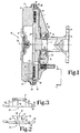
- FIG. 1 is a side, elevational view, partially in cross-section, showing a fluid shear coupling and free floating dam in accordance with the present invention.
- FIG. 2 is a rear, elevational view of a fluid dam according to the present invention.
- FIG. 3 is a top, plan view of the fluid dam of FIG. 2.
- FIG. 4 is a partial, enlarged view of the fluid shear coupling of FIG. 1, showing in particular the placement of the fluid dam relative the annular groove and circumferential cavity in which it is received.
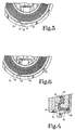
- FIG. 5 is a partial, rear elevation of a fluid shear coupling as shown in FIG. 1, and particularly showing the shear dam in one of its two alternate positions associated with clockwise rotation of the driving member relative the driven member.
- FIG. 6 is a partial, rear elevation of a fluid shear coupling as shown in FIG. 1, and particularly showing the shear dam in one of its two alternate positions associated with counter-clockwise rotation of the driving member relative the driven member.
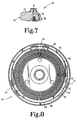
- FIG. 7 is a partial, side elevational view showing the attachment together of the bearing housing and cover.
- FIG. 8 is an elevational view of the bearing housing and rotor, and showing a method of mounting the fluid dams.
- FIG. 1 generally comprises a driving member connected with an external drive source, and a driven member mounted to the driving member for relative rotation about a common axis.
- the driving member includes a disc-shaped rotor 11 secured to a shaft 12.
- the shaft includes a mounting portion 13 which is connectable to an external drive source, such as by the reception of bolts (not shown) through apertures 14.
- a typical external drive source is a vehicle engine for an embodiment in which the apparatus 10 is used as a coupling device for driving a plurality of fan blades mounted to the driven member.
- the driven member 15 includes a bearing housing 16 and a cover 17 secured together by a metal band 18.
- the disc-shaped portion of the driving member 11 defines a shear surface 19 which may have a variety of configurations, such as the annular ridges and grooves as shown in FIG. 1. Other shapes, including planar shear surfaces are known in the art.
- the driving member 11 also has a cylindrical, outer perimeter 20.
- the driven member includes a shear fluid reservoir 21 and a working chamber 22 in which the driving member 11 is received.
- Working chamber 22 includes a shear surface 23 which faces and is adjacent to the shear surface 19 of driving member 11.
- the shear surface 23 may again have a variety of shapes complementary to the configuration of the shear surface 19 of the driving member 11.
- the working chamber defines an annular groove 24 which faces the side of the driving member 11 adjacent the outer perimeter of the driving member.
- the working chamber also defines a circumferential cavity 25 which faces the outer perimeter 20 of the driving member.
- the driven member and driving member are mounted together to have relative rotation about the central axis 26.
- the bearing housing 16 is bearingly mounted to the shaft 12. Inner race 27 of ball bearings 28 is received between the hub portion 29 of the driving member and a shoulder 30 of the shaft 12.
- the bearing housing 16 defines a central hub portion 31 defining a shoulder 32 against which one side of the outer race 33 of the ball bearings is received.
- the hub portion further defines a circumferential recess 34 to which a ring 35 is secured, and bears against the other side of the outer race 33.
- the dam includes a radially extending portion 37 received within the annular groove 24, and an axially extending portion 38 received within the circumferential cavity 25.
- the radially extending portion includes a surface 39 which faces and is adjacent to the side of the driving member 11.
- the axially extending portion includes a surface 40 which faces and is adjacent the outer perimeter 20 of the driving member 11.
- the dam is preferably symmetrical about the plane 41 which extends perpendicular to the axially and radially extending portions at the center of the dam.
- the radially and axially extending portions are designed to direct fluid in the direction of a dump hole 42 (FIG. 4) which opens out on the annular groove 24.
- the dam is designed to permit its reception on either side of the dump hole, the symmetry permitting the dam to be located on either one side or the other of the dump hole and to equally well direct fluid toward the hole.
- the radially extending portion 37 defines a first ramp surface 43 and a second ramp surface 44, tapered inwardly as shown in FIG. 2.
- the axially extending portion 38 includes a first ramp surface 45 and a second ramp surface 46, both being tapered inwardly as shown in FIG. 3.
- the first and second ramp surfaces of the radially extending portion of the dam are angled inwardly in the direction toward the axially extending portion.
- the first and second ramp surfaces of the axially extending portion of the dam are angled inwardly in the direction toward the radially extending portion.
- the axially extending portion 38 has a width dimension in the axial direction 47, as well as a length dimension perpendicular thereto.
- the radially extending portion 37 has a width dimension in the radial direction 48, as well as a length dimension.
- the length dimension of the axially extending portion 38 is greater than the length dimension of the radially extending portion 37, and most preferably is about twice the length dimension of the radially extending portion.
- the dam 36 operates as a pumping element to direct shear fluid through the dump hole and back through radial passageway 49 to the fluid reservoir 21.
- the operation of the dam is comparable to other pumping arrangements.
- the dam is located adjacent the dump hole and the ramp surfaces, such as 43 and 45, direct shear fluid into the dump hole. Due to the nature of coupling by means of the shear fluid, there is a relative rotation between the driving member 11 and the driven member 15. The driving member will therefore force the shear fluid against the ramp surfaces, and the resulting pressure build up will force the fluid through the dump hole and then radially into the reservoir.
- the surfaces 39 and 40 which face the disc-shaped driving member, are shaped and positioned to lie in close proximity to the adjacent surfaces of the driving member.
- FIG. 1 provides an automatic positioning of the dam relative the dump hole based upon the relative rotation of the driving member and the driven member.
- the annular groove 24 extends about the cover 17.
- the circumferential cavity 25 extends preferably for only a short potion of the driven member.
- the cover 17 may include an annular flange 53 which is received within a recess 50 in the bearing housing 16. In the region of the dump hole 42, the flange 53 is terminated, thus leaving a short, circumferential cavity 25.
- the flange 53 terminates in a first end 51 and a second end 52 which act as first and second stops on either side of the dam and the dump hole.
- the dam is sized to be freely movable between the first and second stops, 51 and 52, respectively.
- end stops 51 and 52 are provided in the circumferential cavity 25 by ends of the annular flange 53.
- the end stops could be provided along the annular groove 24, although this is less preferred.
- the dam has a first position (FIG. 6) received against the first stop 51 in which the second ramp surfaces 44 and 46 are located adjacent and facing the dump hole.
- a second position (FIG. 5)
- the dam is located against the second stop 52 and the first ramp surfaces 43 and 45 are located adjacent and facing the dump hole 42.
- the dam is positioned for operation with a driving member which is rotating clockwise (as viewed in FIG. 5) relative the driven member.
- the position shown in FIG. 6 is associated with a driving member which is operating in a counter-clockwise direction (as viewed in FIG. 6) relative the driven member.
- the rotation of the driving member relative the driven member will force fluid in the same direction relative the driven member, and for the embodiment of FIG. 1 will act both to move the dam into the appropriate position and to cause fluid to flow through the dump hole and back to the reservoir.
- FIGS. 7 and 8 An alternate preferred embodiment of the present invention is shown particularly in FIGS. 7 and 8.
- the fluid shear coupling 54 is configured in the same manner as described with respect to the coupling apparatus 10 of FIG. 1, with certain modifications as hereafter described.
- the dams 36 are identical to the dam 36 shown in FIGS. 2 and 3, and remain unattached to either the driving member or rotor 55 or the driven member 56. However, instead of being contained by a cover 17 as in FIG. 1, the dams 36 are received in recesses 57 defined by the bearing housing 58. In the preferred embodiment, three dams and associated recesses 57 are provided in equiradially spaced positions.
- the recesses in the bearing housing receive the axially extending portion 38 of the dams.
- the recesses are sized to fix the dams in a predetermined circumferential position.
- the position of the dams relative the dump holes is controlled by the relative positioning of the bearing housing 58 and the cover 17, as in FIG. 1, placed thereon.
- locating marks may be placed on the outer perimeter of each to identify the placement of the dams and dump holes.
- the bearing housing 58 and cover 17 may be assembled for either clockwise or counterclockwise rotation.
- the bearing housing and cover are then secured together in any of a variety of known manners, such as by the use of a magneformed band as shown in FIG. 7.
- the symmetry of the dams permits the alternate assembly positions.
- the recesses 57 may have differing shapes, provided the dams are positioned appropriately relative the rotor 55.
- the each recess 57 can comprise single, continuous recess shaped complementary to the axially extending portion 38 of a dam.
- the recess in that form would have a continuous outer cylindrical surface against which would be received the axially extending portion 38. Accurate radial positioning of this cylindrical surface would place the inward-facing surface 40 of the dam adjacent the outer perimeter 59 of the rotor 55.
- each cavity 60 and 61 is provided with an outer radius defining an overhanging edge, such as 63.
- the relative size of the dam and the cavities 60 and 61 is such that the ends of the axially extending portion 38 are received under and contained in position by the overhanging edges 63.
- the center portion of the dam is received against the intermediate land 62, providing a somewhat bowed shape to the dam as shown in FIG. 8.
- the bearing housing 58 is typically a cast structure, and the cavities 60 and 61 are cast into the housing. Therefore, the outer surfaces of the cavities are cast surfaces and display the tolerances achievable with casting methods. However, the outer diameter 59 of the rotor 55 and the inner diameter 64 of the bearing housing 58 are preferably machined surfaces to have the higher tolerances achievable with machining methods. It is desirable to place the dams 36 in closely controlled position relative the rotor 55 in order to obtain maximum efficiency of the dams. In the case of a single, continuous recess 57, the position of the dam is established by placement of the axially extending portion 38 against a cast surface.
- the spacing of the dam relative the rotor is diminished.
- the land 62 corresponds to the inner diameter 64 of the bearing housing and therefore may be machined in the same operation.
- the spacing between that portion of the dams and the rotor is dictated by closely controllable dimensions, namely the outer diameter 59 of the rotor, the inner diameter of the land, and the thickness of the axially extending portion of the dam.
- the disengagement speed of the fluid shear coupling can be controlled by adjusting the placement of the dams relative the dump holes. This is accomplished by varying the distance between the dam and the dump hole, since movement of the dam away from the dump hole will raise the disengagement speed. Although there is a sacrifice of dam efficiency as the dam is moved from the dump hole, the decrease in efficiency is at a lesser rate than the change in disengagement speed, and movement of the dam can be effectively used to match the coupling design to application requirements.
- the change in positioning of the dams may be accomplished in two manners.
- the dam stops 51 and 52 may be changed in position, such as by further machining back the flange 53.
- the shape or length of the dam 36 may be altered.
- Adjustment for the embodiment of FIG. 8 is readily accomplished by varying the relative positioning of the bearing housing 58 and the cover. To facilitate this adjustment, the locating marks could be provided on the outer perimeters of the bearing housing and cover either to indicate a specific alignment from which adjustments could be made or to indicate alternate alignments corresponding with different desired positions.
- the dam design of the present invention provides several advantages.
- the dam efficiency is improved due to the nature of the dam's geometry and the geometric planes in which it acts.
- the dam consists of two portions, one extending axially and the other extending radially. Further, the ramp surfaces are angled and direct or focus the fluid towards the dump hole.
- the use of the two portions of the dam provide for fluid to be accumulated both along the shear surface of the driving member and at its outer perimeter.
- the dam could equally be designed to conform to an outer perimeter which is angled at other than 90° to the side surface of the driving member with corresponding changes in the positions of the two dam portions.
- the fan disengaged speed is a result of the remaining fluid in the working chamber in a closed valve, steady state condition. This remaining fluid is converted into torque transmission between the driving member, i.e., the rotor, and the driven member, i.e, the cover or housing.
- the amount of torque transmitted is related to the clearance between the two parts, and the level of fluid therein. The tighter the clearance between the parts, the greater is the torque transmitting ability.
- the present design provides for a rotor having an outside diameter with a minimum clearance equal to the maximum thickness of the axially extending portion of the dam. Therefore, the remaining fluid in the working chamber does not contribute as much to the disengaged fan speed.
Landscapes
- Engineering & Computer Science (AREA)
- General Engineering & Computer Science (AREA)
- Mechanical Engineering (AREA)
- Structures Of Non-Positive Displacement Pumps (AREA)
- Hydraulic Clutches, Magnetic Clutches, Fluid Clutches, And Fluid Joints (AREA)
- Arrangement And Driving Of Transmission Devices (AREA)
- Rotary Pumps (AREA)
Claims (10)
- Accouplement (10) de cisaillement à fluide qui comprend :
un membre d'entraînement comportant une portion (11) en forme de disque présentant un côté définissant une surface de cisaillement (19) et présentant un périmètre extérieur cylindrique (20) ;
un membre entraîné (15) comportant un réservoir (21) de fluide de cisaillement et définissant une enceinte de travail (22) à l'intérieur de laquelle est reçu ledit membre d'entraînement (11), l'enceinte de travail (22) comportant une surface de cisaillement (23) faisant face et adjacente à la surface de cisaillement (19) dudit membre d'entraînement (11), l'enceinte de travail (22) définissant une gorge annulaire (24) faisant face au côté dudit membre d'entraînement (11) adjacent au périmètre extérieur (20) dudit membre d'entraînement (11), l'enceinte de travail (22) définissant également une cavité circonférentielle (25) faisant face au périmètre extérieur (20) dudit membre d'entraînement (11) ;
un moyen de montage pour monter ledit membre entraîné (15) sur ledit membre d'entraînement (11) pour être capable de rotation autour d'un axe commun (26) ; et un barrage (36) en forme de L d'une pièce, caractérisé en ce que :
le barrage (36) en forme de L comporte une portion (37) s'étendant radialement et une portion (38) s'étendant axialement, la portion (37) s'étendant radialement étant reçue à l'intérieur de la gorge annulaire (24) dans l'enceinte de travail (22) et présentant une surface (39) faisant face et adjacente au côté dudit membre d'entraînement (11), la portion (38) s'étendant axialement étant reçue à l'intérieur de la cavité circonférentielle (25) dans l'enceinte de travail (22) et présentant une surface (40) faisant face et adjacente au périmètre extérieur (20) dudit membre d'entraînement (11), chacune des portions (36, 37) s'étendant radialement et axialement comportant une première face de rampe (43, 45) à une extrémité tournée généralement dans une première direction et une seconde face de rampe (44, 46) à l'extrémité opposée tournée généralement dans une seconde direction opposée à la première direction, le barrage (36) étant dépourvu d'attachement au membre entraîné. - Un accouplement de cisaillement à fluide selon la revendication 1, caractérisé en ce que ledit membre entraîné (15) comporte un bâti de support (16), une enveloppe (17), et un moyen d'accouplement (18) destiné à accoupler l'enveloppe (17) au bâti de support (16) ;
l'un parmi le bâti de support (16) et l'enveloppe (17) définissant un passage de retour du fluide comportant un trou de déversement (42) débouchant dans la gorge annulaire (24), l'autre parmi le bâti de support (16) et l'enveloppe (17) définissant une cavité (25) à l'intérieur de laquelle est reçu ledit barrage (36), le moyen d'accouplement dudit membre entraîné (15) étant destiné à l'accouplement sélectif de l'enveloppe (17) au bâti de support (16), ledit barrage (36) présentant l'une de deux positions alternatives, la première position étant celle dans laquelle les secondes faces de rampe (44, 46) sont situées adjacentes et faisant face au trou de déversement (42) et la seconde position étant celle dans laquelle les premières faces de rampe (43, 45) sont situées adjacentes et faisant face au trou de déversement (42). - Accouplement de cisaillement à fluide selon la revendication 1 ou 2, dans lequel le bâti de support (16) définit une cavité dans laquelle est reçue la portion (37) s'étendant axialement dudit barrage (36).
- Accouplement de cisaillement à fluide selon une revendication précédente quelconque, dans lequel ledit barrage (36) est symmétrique autour d'un plan (41) s'étendant perpendiculairement aux portions (38, 37) s'étendant axialement et s'étendant radialement à travers le centre dudit barrage (36).
- Accouplement de cisaillement à fluide selon une revendication précédente quelconque, dans lequel les première (45) et seconde (46) faces de rampe de la portion (38) s'étendant axialement dudit barrage (36) sont orientées vers l'intérieur dans le sens allant en direction de la portion (37) s'étendant radialement.
- Accouplement de cisaillement à fluide selon un revendication précédente quelconque, dans lequel les première (43) et seconde (44) faces de rampe de la portion (37) s'étendant radialement dudit barrage (36) sont orientées vers l'intérieur dans le sens allant en direction de la portion (37) s'étendant axialement.
- Accouplement de cisaillement à fluide selon une revendication précédente quelconque, dans lequel :
ledit membre entraîné (15) définit un passage de retour du fluide comportant un trou de déversement (45) débouchant dans la gorge annulaire (24) ;
l'enceinte de travail (22) définit des première et seconde butées (51, 52) de chaque côté dudit barrage (36) et du trou de déversement (42), la première butée (51) étant du même côté dudit barrage (36) que les premières faces de rampe (43, 45) et la seconde butée (52) étant du même côté dudit barrage (36) que les secondes faces de rampe (44, 46) ;
ledit barrage (36) étant capable de déplacement librement à l'intérieur de la gorge annulaire (24) et de la cavité circonférentielle (25) entre la première butée (51) et la seconde butée (52), et présentant une première position contre la première butée (51) dans laquelle les secondes faces de rampe (44, 46) sont situées adjacentes et faisant face au trou de déversement (42), et présentant une seconde position contre la seconde butée (52) dans laquelle les premières faces de rampe (43, 45) sont situées adjacentes et faisant face au trou de déversement (42). - Accouplement de cisaillement à fluide selon la revendication 7, dans lequel les première et seconde butées (51, 52) sont définies par la cavité circonférentielle (25) de l'enceinte de travail (22).
- Accouplement de cisaillement à fluide selon une revendication précédente quelconque, dans lequel la portion (38) s'étendant axialement dudit barrage (36) présente une dimension de largeur dans la direction axiale et une dimension de longueur, et dans lequel la portion (37) s'étendant radialement dudit barrage (36) présente une dimension de largeur dans la direction radiale et une dimension de longueur, la dimension de longueur de la portion (38) s'étendant axialement étant supérieure à la dimension de longueur de la portion (37) s'étendant radialement.
- Accouplement de cisaillement à fluide selon la revendication 9, dans lequel la dimension de longueur de la portion (38) s'étendant axialement est environ deux fois la dimension de longueur de la portion (37) s'étendant radialement.
Applications Claiming Priority (2)
| Application Number | Priority Date | Filing Date | Title |
|---|---|---|---|
| US07/414,765 US4977990A (en) | 1989-09-29 | 1989-09-29 | Free floating dam for a fluid shear coupling apparatus |
| US414765 | 1989-09-29 |
Publications (2)
| Publication Number | Publication Date |
|---|---|
| EP0420601A1 EP0420601A1 (fr) | 1991-04-03 |
| EP0420601B1 true EP0420601B1 (fr) | 1994-07-06 |
Family
ID=23642863
Family Applications (1)
| Application Number | Title | Priority Date | Filing Date |
|---|---|---|---|
| EP90310517A Expired - Lifetime EP0420601B1 (fr) | 1989-09-29 | 1990-09-26 | Barrage à mouvement libre pour appareil d'accouplement à frottement visqueux |
Country Status (4)
| Country | Link |
|---|---|
| US (1) | US4977990A (fr) |
| EP (1) | EP0420601B1 (fr) |
| JP (1) | JP2839204B2 (fr) |
| DE (1) | DE69010441T2 (fr) |
Families Citing this family (4)
| Publication number | Priority date | Publication date | Assignee | Title |
|---|---|---|---|---|
| DE4242666A1 (de) * | 1992-12-17 | 1994-06-23 | Behr Gmbh & Co | Flüssigkeitsreibungskupplung |
| US7650974B2 (en) * | 2005-05-02 | 2010-01-26 | Borgwarner Inc. | OD wiper |
| DE102006020136B4 (de) * | 2006-04-04 | 2017-11-09 | Borgwarner Inc. | Strömungsmittelkupplungsvorrichtung |
| US9624988B2 (en) | 2012-09-22 | 2017-04-18 | Horton, Inc. | Viscous clutch with return bore through rotor |
Family Cites Families (14)
| Publication number | Priority date | Publication date | Assignee | Title |
|---|---|---|---|---|
| US3174600A (en) * | 1961-05-18 | 1965-03-23 | Oldberg Sidney | Temperature-responsive fluid clutch |
| US3463282A (en) * | 1967-01-21 | 1969-08-26 | Aisin Seiki | Controlled type fluid coupling |
| US4086989A (en) * | 1976-11-15 | 1978-05-02 | Wallace Murray Corporation | Temperature controlled hydraulic coupling with moveable dam |
| US4086988A (en) * | 1976-11-15 | 1978-05-02 | Wallace Murray Corporation | Rolling dam temperature controlled hydraulic coupling |
| US4271946A (en) * | 1979-01-17 | 1981-06-09 | Eaton Corporation | Pumping element for temperature responsive viscous fan drive |
| DE3041829C2 (de) * | 1980-11-06 | 1984-07-05 | Süddeutsche Kühlerfabrik Julius Fr. Behr GmbH & Co KG, 7000 Stuttgart | Flüssigkeitsreibungskupplung |
| DE3041793C2 (de) * | 1980-11-06 | 1984-08-02 | Süddeutsche Kühlerfabrik Julius Fr. Behr GmbH & Co KG, 7000 Stuttgart | Flüssigkeitsreibungskupplung |
| US4383597A (en) * | 1980-12-22 | 1983-05-17 | Wallace Murray Corporation | Fluid shear coupling apparatus |
| US4403684A (en) * | 1980-12-22 | 1983-09-13 | Wallace Murray Corporation | Fluid shear coupling apparatus |
| US4437554A (en) * | 1981-06-19 | 1984-03-20 | Household Manufacturing Inc. | Fluid shear coupling apparatus |
| DE3147797A1 (de) * | 1981-12-03 | 1983-06-16 | Süddeutsche Kühlerfabrik Julius Fr. Behr GmbH & Co KG, 7000 Stuttgart | Fluessigkeitsreibungskupplung |
| DE3328646A1 (de) * | 1983-08-09 | 1985-02-21 | Fichtel & Sachs Ag, 8720 Schweinfurt | Drehrichtungsunabhaengige visko-luefterkupplung |
| US4741421A (en) * | 1984-10-05 | 1988-05-03 | General Motors Corporation | Viscous clutch for engine cooling fan with improved fluid flow path control and feed to shear zone |
| JP6331009B2 (ja) | 2014-04-02 | 2018-05-30 | 株式会社大林組 | 揚水井戸構造 |
-
1989
- 1989-09-29 US US07/414,765 patent/US4977990A/en not_active Expired - Lifetime
-
1990
- 1990-09-26 DE DE69010441T patent/DE69010441T2/de not_active Expired - Lifetime
- 1990-09-26 EP EP90310517A patent/EP0420601B1/fr not_active Expired - Lifetime
- 1990-09-28 JP JP2260332A patent/JP2839204B2/ja not_active Expired - Lifetime
Also Published As
| Publication number | Publication date |
|---|---|
| DE69010441T2 (de) | 1994-11-24 |
| US4977990A (en) | 1990-12-18 |
| DE69010441D1 (de) | 1994-08-11 |
| JP2839204B2 (ja) | 1998-12-16 |
| JPH03153933A (ja) | 1991-07-01 |
| EP0420601A1 (fr) | 1991-04-03 |
Similar Documents
| Publication | Publication Date | Title |
|---|---|---|
| US4295550A (en) | Viscous fluid coupling device | |
| US3055473A (en) | Fluid coupling device | |
| JP3033989B2 (ja) | トルクコンバータ用のバイパスクラッチとロックアップクラッチ | |
| US3990556A (en) | Viscous fluid coupling device | |
| EP0015643A2 (fr) | Dispositif d'accouplement hydraulique à temps de réponse amélioré | |
| US3413925A (en) | Centrifugal pump having thrust balancing means | |
| US6669439B2 (en) | Variable flow impeller-type water pump with movable shroud | |
| US6530748B2 (en) | Enhanced fan and fan drive assembly | |
| US4784587A (en) | Pump apparatus | |
| JPS5844896B2 (ja) | リユウタイツギテ | |
| EP0014072B1 (fr) | Transmission à fluide visqueux d'un ventilateur | |
| US3227254A (en) | Fluid coupling | |
| US4190139A (en) | Centering abutment for viscous fluid drive | |
| US4974712A (en) | Fluid coupling device and improved valving therefor | |
| US4116318A (en) | Fluid flow restriction path in viscous fluid clutch | |
| US4269295A (en) | Torque transmitting fluid couplings | |
| EP0420601B1 (fr) | Barrage à mouvement libre pour appareil d'accouplement à frottement visqueux | |
| JPS6242172B2 (fr) | ||
| EP3384174B1 (fr) | Système de capture de fluide viscocoupleur | |
| US3552532A (en) | Fluid coupling device | |
| US5101950A (en) | Fluid coupling device with improved dump time | |
| US4627523A (en) | Fluid coupling device with improved fluid cooling | |
| US4238015A (en) | Temperature responsive viscous fan drive | |
| EP0426318B1 (fr) | Système d'entraînement d'un ventilateur pour automobile | |
| US4131386A (en) | Sealing system for centrifugal pump |
Legal Events
| Date | Code | Title | Description |
|---|---|---|---|
| PUAI | Public reference made under article 153(3) epc to a published international application that has entered the european phase |
Free format text: ORIGINAL CODE: 0009012 |
|
| AK | Designated contracting states |
Kind code of ref document: A1 Designated state(s): DE FR GB SE |
|
| 17P | Request for examination filed |
Effective date: 19910924 |
|
| 17Q | First examination report despatched |
Effective date: 19921112 |
|
| GRAA | (expected) grant |
Free format text: ORIGINAL CODE: 0009210 |
|
| AK | Designated contracting states |
Kind code of ref document: B1 Designated state(s): DE FR GB SE |
|
| REF | Corresponds to: |
Ref document number: 69010441 Country of ref document: DE Date of ref document: 19940811 |
|
| ET | Fr: translation filed | ||
| EAL | Se: european patent in force in sweden |
Ref document number: 90310517.9 |
|
| PLBE | No opposition filed within time limit |
Free format text: ORIGINAL CODE: 0009261 |
|
| STAA | Information on the status of an ep patent application or granted ep patent |
Free format text: STATUS: NO OPPOSITION FILED WITHIN TIME LIMIT |
|
| 26N | No opposition filed | ||
| REG | Reference to a national code |
Ref country code: FR Ref legal event code: CD |
|
| REG | Reference to a national code |
Ref country code: GB Ref legal event code: IF02 |
|
| PGFP | Annual fee paid to national office [announced via postgrant information from national office to epo] |
Ref country code: GB Payment date: 20090807 Year of fee payment: 20 Ref country code: SE Payment date: 20090904 Year of fee payment: 20 |
|
| PGFP | Annual fee paid to national office [announced via postgrant information from national office to epo] |
Ref country code: DE Payment date: 20090930 Year of fee payment: 20 |
|
| REG | Reference to a national code |
Ref country code: GB Ref legal event code: PE20 Expiry date: 20100925 |
|
| EUG | Se: european patent has lapsed | ||
| PG25 | Lapsed in a contracting state [announced via postgrant information from national office to epo] |
Ref country code: GB Free format text: LAPSE BECAUSE OF EXPIRATION OF PROTECTION Effective date: 20100925 |
|
| PGFP | Annual fee paid to national office [announced via postgrant information from national office to epo] |
Ref country code: FR Payment date: 20090916 Year of fee payment: 20 |
|
| PG25 | Lapsed in a contracting state [announced via postgrant information from national office to epo] |
Ref country code: DE Free format text: LAPSE BECAUSE OF EXPIRATION OF PROTECTION Effective date: 20100926 |