EP0420609A2 - Ein/Aus Lastunterbrechungsschalter - Google Patents
Ein/Aus Lastunterbrechungsschalter Download PDFInfo
- Publication number
- EP0420609A2 EP0420609A2 EP90310529A EP90310529A EP0420609A2 EP 0420609 A2 EP0420609 A2 EP 0420609A2 EP 90310529 A EP90310529 A EP 90310529A EP 90310529 A EP90310529 A EP 90310529A EP 0420609 A2 EP0420609 A2 EP 0420609A2
- Authority
- EP
- European Patent Office
- Prior art keywords
- contact
- shaft
- assembly
- set forth
- housing
- Prior art date
- Legal status (The legal status is an assumption and is not a legal conclusion. Google has not performed a legal analysis and makes no representation as to the accuracy of the status listed.)
- Withdrawn
Links
- 238000000034 method Methods 0.000 claims abstract description 9
- 230000000712 assembly Effects 0.000 claims description 19
- 238000000429 assembly Methods 0.000 claims description 19
- 125000006850 spacer group Chemical group 0.000 claims description 17
- 229910052802 copper Inorganic materials 0.000 claims description 16
- 239000010949 copper Substances 0.000 claims description 16
- RYGMFSIKBFXOCR-UHFFFAOYSA-N Copper Chemical compound [Cu] RYGMFSIKBFXOCR-UHFFFAOYSA-N 0.000 claims description 14
- 229910000831 Steel Inorganic materials 0.000 claims description 11
- 239000010959 steel Substances 0.000 claims description 11
- 238000000926 separation method Methods 0.000 claims description 5
- WFKWXMTUELFFGS-UHFFFAOYSA-N tungsten Chemical compound [W] WFKWXMTUELFFGS-UHFFFAOYSA-N 0.000 claims description 5
- 229910052721 tungsten Inorganic materials 0.000 claims description 5
- 239000010937 tungsten Substances 0.000 claims description 5
- 230000004907 flux Effects 0.000 claims description 4
- 239000012815 thermoplastic material Substances 0.000 claims description 3
- VYZAMTAEIAYCRO-UHFFFAOYSA-N Chromium Chemical compound [Cr] VYZAMTAEIAYCRO-UHFFFAOYSA-N 0.000 claims description 2
- 230000013011 mating Effects 0.000 claims description 2
- 239000003989 dielectric material Substances 0.000 claims 2
- 230000006835 compression Effects 0.000 description 2
- 238000007906 compression Methods 0.000 description 2
- 239000012141 concentrate Substances 0.000 description 2
- 238000010276 construction Methods 0.000 description 2
- 210000004907 gland Anatomy 0.000 description 2
- 238000009826 distribution Methods 0.000 description 1
- 238000004519 manufacturing process Methods 0.000 description 1
- 239000007787 solid Substances 0.000 description 1
- 238000003466 welding Methods 0.000 description 1
Images


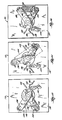

Classifications
-
- H—ELECTRICITY
- H01—ELECTRIC ELEMENTS
- H01H—ELECTRIC SWITCHES; RELAYS; SELECTORS; EMERGENCY PROTECTIVE DEVICES
- H01H9/00—Details of switching devices, not covered by groups H01H1/00 - H01H7/00
-
- H—ELECTRICITY
- H01—ELECTRIC ELEMENTS
- H01H—ELECTRIC SWITCHES; RELAYS; SELECTORS; EMERGENCY PROTECTIVE DEVICES
- H01H21/00—Switches operated by an operating part in the form of a pivotable member acted upon directly by a solid body, e.g. by a hand
- H01H21/02—Details
- H01H21/18—Movable parts; Contacts mounted thereon
- H01H21/36—Driving mechanisms
- H01H21/40—Driving mechanisms having snap action
-
- H—ELECTRICITY
- H01—ELECTRIC ELEMENTS
- H01H—ELECTRIC SWITCHES; RELAYS; SELECTORS; EMERGENCY PROTECTIVE DEVICES
- H01H1/00—Contacts
- H01H1/02—Contacts characterised by the material thereof
- H01H1/021—Composite material
-
- H—ELECTRICITY
- H01—ELECTRIC ELEMENTS
- H01H—ELECTRIC SWITCHES; RELAYS; SELECTORS; EMERGENCY PROTECTIVE DEVICES
- H01H1/00—Contacts
- H01H1/12—Contacts characterised by the manner in which co-operating contacts engage
- H01H1/36—Contacts characterised by the manner in which co-operating contacts engage by sliding
- H01H1/365—Bridging contacts
-
- H—ELECTRICITY
- H01—ELECTRIC ELEMENTS
- H01H—ELECTRIC SWITCHES; RELAYS; SELECTORS; EMERGENCY PROTECTIVE DEVICES
- H01H1/00—Contacts
- H01H1/12—Contacts characterised by the manner in which co-operating contacts engage
- H01H1/36—Contacts characterised by the manner in which co-operating contacts engage by sliding
- H01H1/42—Knife-and-clip contacts
-
- H—ELECTRICITY
- H01—ELECTRIC ELEMENTS
- H01H—ELECTRIC SWITCHES; RELAYS; SELECTORS; EMERGENCY PROTECTIVE DEVICES
- H01H1/00—Contacts
- H01H1/50—Means for increasing contact pressure, preventing vibration of contacts, holding contacts together after engagement, or biasing contacts to the open position
- H01H1/54—Means for increasing contact pressure, preventing vibration of contacts, holding contacts together after engagement, or biasing contacts to the open position by magnetic force
-
- H—ELECTRICITY
- H01—ELECTRIC ELEMENTS
- H01H—ELECTRIC SWITCHES; RELAYS; SELECTORS; EMERGENCY PROTECTIVE DEVICES
- H01H33/00—High-tension or heavy-current switches with arc-extinguishing or arc-preventing means
- H01H33/60—Switches wherein the means for extinguishing or preventing the arc do not include separate means for obtaining or increasing flow of arc-extinguishing fluid
- H01H33/68—Liquid-break switches, e.g. oil-break
-
- H—ELECTRICITY
- H01—ELECTRIC ELEMENTS
- H01H—ELECTRIC SWITCHES; RELAYS; SELECTORS; EMERGENCY PROTECTIVE DEVICES
- H01H11/00—Apparatus or processes specially adapted for the manufacture of electric switches
-
- H—ELECTRICITY
- H01—ELECTRIC ELEMENTS
- H01H—ELECTRIC SWITCHES; RELAYS; SELECTORS; EMERGENCY PROTECTIVE DEVICES
- H01H19/00—Switches operated by an operating part which is rotatable about a longitudinal axis thereof and which is acted upon directly by a solid body external to the switch, e.g. by a hand
- H01H19/02—Details
- H01H19/10—Movable parts; Contacts mounted thereon
- H01H19/14—Operating parts, e.g. turn knob
-
- H—ELECTRICITY
- H01—ELECTRIC ELEMENTS
- H01H—ELECTRIC SWITCHES; RELAYS; SELECTORS; EMERGENCY PROTECTIVE DEVICES
- H01H19/00—Switches operated by an operating part which is rotatable about a longitudinal axis thereof and which is acted upon directly by a solid body external to the switch, e.g. by a hand
- H01H19/64—Encased switches adapted for ganged operation when assembled in a line with identical switches, e.g. stacked switches
-
- H—ELECTRICITY
- H01—ELECTRIC ELEMENTS
- H01H—ELECTRIC SWITCHES; RELAYS; SELECTORS; EMERGENCY PROTECTIVE DEVICES
- H01H33/00—High-tension or heavy-current switches with arc-extinguishing or arc-preventing means
- H01H33/02—Details
- H01H33/04—Means for extinguishing or preventing arc between current-carrying parts
- H01H33/12—Auxiliary contacts on to which the arc is transferred from the main contacts
- H01H33/121—Load break switches
Definitions
- the invention relates to on/off loadbreak switches, or to "quick-make and quick-break" switches.
- Such switches are typically used in distribution transformers and are immersed in transformer oil. See, for example, U.S. Patent Nos. 3,590,183, 4,412,116, and 4,532,386.
- the invention provides an improved on/off loadbreak switch.
- the switch comprises a housing including three substantially identical sections. The use of housing sections facilitates assembly of the switch, as will be explained hereinafter.
- the switch also comprises six fixed contact assemblies, with two contact assemblies being mounted in opposed, facing relation on each of the housing sections.
- Each contact assembly includes a copper spacer, a stack of copper shims mounted on one side of the spacer, and a stack of copper shims mounted on the other side of the spacer so that the shim stacks are spaced from each other. Copper shims are preferred over solid copper members because shims are more flexible and do not work harden as quickly.
- Each shim stack has thereon an arc-resistant pad facing and spaced from the pad on the other shim stack.
- Each contact assembly further includes a spring arrangement for biasing the backing members, and thus the shim stacks, toward each other.
- the spring arrangement includes a post having enlarged ends and extending through the backing members, the shim stacks and the spacer.
- the spring arrangement also includes a compression spring extending between one end of the post and one of the backing members. The other end of the post engages the other backing member. The spring acts through the post to bias the shim stacks against the spacer or toward each other.
- the spring of each contact assembly is housed in a respective pocket in the associated housing section. This protects the spring from arcing.
- the switch also comprises a shaft or rotor supported by the housing for pivotal movement relative thereto about an axis.
- the shaft includes two substantially identical halves split along a plane having therein the shaft axis. In other words, the shaft is split longitudinally.
- the shaft halves are secured together by bolts, screws or other suitable means. The use of identical halves reduces manufacturing costs.
- the switch further comprises three contact blades captured or sandwiched between the shaft halves.
- the contact blades are spaced longitudinally of the shaft and are spaced apart the same distance as the fixed contact assemblies are spaced apart. Each blade is aligned with a pair of contact assemblies.
- the shaft halves have thereon deformable or crushable projections that are crushed against the contact blades when the blades are sandwiched between the shaft halves. This provides a tight fit between the blades and the shaft halves and thereby substantially prevents lateral movement of the blades relative to the shaft.
- the switch further comprises an over-center spring device or motor assembly for pivoting the shaft relative to the housing.
- the motor assembly moves the shaft between a closed position in which each contact blade engages the aligned pair of contact assemblies and an open position in which the contact blades are disengaged from the contact assemblies.
- the shaft moves approximately 90° between the closed position and the open position.
- the switch is assembled by sandwiching the contact blades between the shaft halves and securing the resultant shaft and contact assembly to the motor assembly.
- the housing sections are placed over the shaft or are located in surrounding relation to the shaft and contact assembly. This is done by passing the shaft and contact assembly through openings in the housing sections.
- the shaft is moved to the closed position and the contact blades are placed in engagement with their respective fixed contact assemblies. This properly aligns the housing sections relative to the shaft and contact assembly.
- the housing sections are secured relative to each other and relative to the motor assembly.
- This method of assembly permits the housing sections to be properly aligned with the shaft and contact assembly. This in turn substantially assures that the contact blades will properly engage the fixed contact assemblies when the shaft is moved to the closed position.
- the spring arrangement compensates for unexpected misalignment of the contact blade and the fixed contact assembly. In other words, both pads will still be biased against the contact blade even if the contact blade is not perfectly positioned between the pads but is located closer to one of the pads. Also, the coil spring provides a more consistent force than would be provided by leaf springs.
- a loadbreak switch 10 embodying the invention is illustrated in the drawings. Although a three-phase switch is shown, it should be understood that the invention is equally applicable to single-phase switches, or to switches having any number of contacts.
- the switch 10 comprises (see Fig. 1) a housing 12 which has a longitudinal axis 14 and which, in the preferred embodiment, includes an end section 16, a middle section 18, and an end section 20.
- the sections 16, 18 and 20 are substantially identical and are preferably fabricated of thermoplastic material.
- Each section 16, 18 or 20 includes (see Figs. 1 and 13) a generally planar base plate 22.
- the base plate 22 has therein an opening 24 centered on the housing axis 14.
- Each section 16, 18 or 20 also includes (see Figs. 1, 13 and 14) spaced flanges 26 projecting from one side of the base plate 22 at the opposite ends thereof, and four legs 28 projecting from the other side of the base plate 22 at the four corners thereof.
- Each section 16, 18 or 20 also includes a cross member 32 extending between one pair of legs 28, and a cross member 32 extending between the other pair of legs 28.
- Each section 16, 18 or 20 further includes (see Figs. 1, 4, 13 and 14) a mounting projection 34 located between the legs 28 at one end of the base plate 22, and a mounting projection 36 located between the legs 28 at the other end of the base plate 22.
- the base plate 22 has therein a pocket 38 adjacent the mounting projection 34 and has therein a pocket 40 adjacent the mounting projection 36.
- the sections 16, 18 and 20 are stacked with the flanges 26 of the middle section 18 overlapping the legs 28 of the end section 16, and with the flanges 26 of the end section 20 overlapping the legs 28 of the middle section 18.
- the sections 16, 18 and 20 are secured to each other by nuts 41 and bolts 42 extending through the apertures 30 and 31 in the overlapping flanges 26 and legs 28.
- the switch 10 also comprises (see Figs. 1, 3 and 4) six fixed contact assemblies 44, with each contact assembly 44 being mounted on a respective one of the mounting projections 34 and 36.
- Each contact assembly 44 includes (see Fig. 4) contact portions 46 and 48, which are preferably stacks of copper shims.
- Each assembly 44 also includes means for maintaining a minimum spacing between the stacks of shims 46 and 48. While various suitable spacing means can be employed, in the preferred embodiment, such means include a copper spacer 50. One end of the spacer 50 extends between the stacks 46 and 48, and the other end of the spacer 50 provides a location for connecting a power line.
- the shim stacks 46 and 48 are fixed to the spacer 50 by an eyelet 52, and the contact assembly 44 is secured to the associated mounting projection 34 or 36 by a screw 54 that extends through the eyelet 52 and that threadedly engages the associated mounting projection 34 or 36.
- Each contact assembly also includes arc-resistant pads 55 secured to the inner surfaces of the shim stacks 46 and 48.
- Each of the pads 55 includes a contact tip or portion which engages the associated contact blade (described below) and which is fabricated of 70 percent tungsten and 30 percent copper. The pads 55 are spaced from each other when the shim stacks 46 and 48 are at their minimum spacing.
- Each contact assembly 44 also includes (see Fig. 4) means for biasing the shim stacks 46 and 48 together or toward each other. While various suitable biasing means can be used, in the illustrated construction, such means includes a steel backing member or plate 56 abutting the outer surface of the shim stack 46, and a steel backing member or plate 58 abutting the outer surface of the shim stack 48. As mentioned previously, the steel plates 56 and 58 concentrate the magnetic flux of the contact assembly 44.
- the biasing means also includes means for biasing the backing members 56 and 58 toward each other.
- the means for biasing the backing members 56 and 58 includes a post 60 extending through the members 56 and 58, the shim stacks 46 and 48 and the spacer 50.
- the post 60 has enlarged ends 62 and 64, and the means for biasing the backing members 56 and 58 also includes a compression spring 66 extending between the end 62 of the post 60 and a washer 68 engaging the steel plate 58.
- the end 64 of the post 60 engages the steel plate 56.
- the spring 66 acts through the washer 68 and the post 60 to bias the shim stacks 46 and 48 against the spacer 50 or toward each other. As shown in Fig. 4, the spring 66 is housed in the associated pocket 38 or 40. This protects the spring 66 from arcing.
- the switch also comprises (see Figs. 1, 2 and 5-9) a shaft or rotor 70 supported by the housing 12 for pivotal movement relative thereto about the housing axis 14.
- the shaft 70 includes two substantially identical halves 72 fabricated of thermoplastic material. As shown in Figs. 5 and 8, each half 72 includes a semicircular wall 74 having opposite ends. The ends of the wall 74 define a generally planar surface 76 which faces the corresponding surface 76 of the other half 72.
- the surface 76 has thereon (see Fig. 2) three aligned pairs of projections 77, each of which has therein a recess 78. Each recess 78 is defined by (see Fig.
- the surface 76 also has thereon (see Fig. 2) at least four pairs of aligned projections 86 and 87 and at least two pairs of aligned projections 88 and 89.
- the projections 86-89 define (see Figs. 5-9) a generally planar mating surface 90 that mates with the corresponding surface 90 of the other half 72 and that defines a plane 91 having therein the housing axis 14.
- the shaft 70 is split longitudinally or axially.
- Each projection 86 has thereon (see Figs. 2 and 9) an annular projection 92, and each projection 87 has therein a circular recess 94.
- the shaft halves 72 are aligned with each other so that each projection 86 abuts a projection 87 on the other half 72, with each recess 94 receiving a projection 92, so that each projection 88 abuts a projection 84, and so that each recess 78 is aligned with a recess 78 in the other half 72.
- the interengaging projections 92 and recesses 94 prevent relative axial movement of the shaft halves 72.
- the aligned recesses 78 define (see Fig. 5) openings 96 in the shaft 70.
- the shaft halves 72 are secured to each other by bolts or screws 98 (Figs. 1, 5, 7 and 9) extending through aligned projections 86 and 87.
- the shaft halves 72 could be ultrasonically or otherwise welded together. Because the projections 86-89 are aligned and abut, the surfaces 76 are slightly spaced from each other, as shown in Fig. 5. This affords oil flow into and out of the shaft 70. Openings 100 (Fig. 1) in the shaft halves 72 are provided for the same reason.
- One end of the shaft 70 defines (see Figs. 1, 2 and 13) an annular bearing surface 102 supported by base plate 22 of the end housing section 16.
- the other end of the shaft 70 has therein (see Fig. 7) a hexagonal opening 104.
- the opening 104 is defined by walls 106 having thereon projections 108.
- the switch 10 further comprises (see Figs. 1 and 3-6) three movable contacts or contact blades 110 supported by the shaft 70 for pivotal movement therewith.
- the contact blades 110 are made of chrome copper (CDA 182) so that the blades 110 retain their strength under arcing and are resistant to welding to the contact pads 55 under conditions of high fault current.
- CDA 182 chrome copper
- each contact blade 110 is sandwiched or captured between the shaft halves 72 and extends through an opening 96 defined by an aligned pair of recesses 78, so that the opposite ends of the blade 110 extend outwardly of the rotor 70.
- Each blade 110 has therein (see Figs.
- each contact blade 110 includes means for facilitating separation of the contact portions 46 and 48 of the associated fixed contact assembly 44. While various suitable means can be employed, in the preferred embodiment, such means includes, on each end of each contact blade 110, a beveled portion 115.
- the switch 10 further comprises (see Figs. 1 and 10-12) means for pivotally moving the shaft 70 between a closed position (Figs. 1, 3 and 4) in which each blade 110 engages a pair of contact assemblies 44 and an open position (not shown) in which the blades 110 are disengaged from the contact assemblies 44.
- a closed position Figs. 1, 3 and 4
- an open position not shown
- the blades 110 are disengaged from the contact assemblies 44.
- the shaft 70 moves approximately 90° between the closed position and the open position. While various suitable moving means can be employed, in the preferred embodiment, such means includes (see Fig.
- a motor assembly 116 including an inner motor plate 118 fixed to the legs 28 of the end housing section 20 by nuts 41 and bolts 42 extending through the apertures 31 of the housing section 20, and an outer plate 120 spaced from the inner plate 118 by spacers 122.
- the outer plate 120 and the spacers 122 are secured to the inner plate 118 by bolts 124.
- the outer plate 120 is preferably secured to the tank wall 126 of a transformer by suitable means such as bolts (not shown).
- the motor assembly 116 also includes (see Fig. 1) an input shaft 128 which is pivotably supported by the outer plate 120 and which extends through the tank wall 126.
- a gland/seal assembly 129 is sealingly secured to the tank wall 126, and the input shaft 128 extends through the gland/seal assembly 129.
- O-rings 130 provide a seal between the shaft 128 and the assembly 129.
- the outer end of the input shaft 128 has fixed thereon a handle 131 adapted to be rotated by an operator so as to rotate the input shaft 128.
- the motor assembly 116 also includes (see Fig. 1) an output shaft 132 pivotably supported on the inner plate 118 by a bearing 133.
- the output shaft 132 has (see Fig. 7) a hexagonal inner end 134 housed in the opening 104 in the shaft 70, so that the output shaft 132 is effectively splined to the shaft 70.
- the inner end 134 of the output shaft 132 has therein depressions or recesses 136 that receive the projections 108 on the shaft halves 72, so that interengagement of the projections 108 and the recesses 136 prevents axial movement of the output shaft 132 relative to the shaft 70.
- the motor assembly 116 also includes means for converting pivotal movement of the input shaft 128 into a "snap action" pivotal movement of the output shaft 132.
- this means includes (see Figs. 1 and 10-12) an L-shaped outer lever 138 fixed to the input shaft 128 for common movement therewith, and an L-shaped inner lever 140 fixed to the output shaft 132 for common movement therewith.
- This means further includes (see Figs. 10-12) stops 142, 144, 146 and 148 extending inwardly from the outer plate 120, cam members 150 and 152 pivotally mounted on the outer plate 120, a spring 154 extending between the levers 138 and 140, and stops 156 and 158 extending outwardly from the inner plate 118.
- the spring 154 biases the inner lever 140 against the stop 156 and biases the outer lever 138 against the stop 142. Also, the cam member 150 is trapped between the lever 140 and the stop 144 and the cam member 152 is trapped between the lever 138 and the stop 148.
- the input shaft 128 and the outer lever 138 are rotated counterclockwise (as shown in Figs. 10-12). This moves the outer lever 138 away from the stop 142 and extends the spring 154.
- the outer lever 138 reaches the position shown in Fig. 11, the lower end (as shown in Fig.
- the switch 70 is assembled as follows. First, the contact blades 110 are sandwiched between the shaft halves 72, and the shaft halves 72 are secured to each other by the screws 98. When the screws 98 are tightened, the deformable projections 84 are crushed against the blades 110 to provide a tight fit between the shaft 70 and the blades 110. When the shaft halves 72 are placed together to capture the contact blades 110, the shaft halves 72 are concurrently placed over the inner end 134 of the output shaft 132 so that the shaft halves 72 capture the inner end 134 of the output shaft 132 and the projections 108 on the shaft halves 72 are received in the depressions 136 in the output shaft 132. Thus, the shaft 70 and the contact blades 110 are assembled to provide a shaft and contact assembly 170, which assembly 170 is connected to the motor assembly 116.
- the housing sections 16, 18 and 20 are placed over the shaft 70.
- the housing sections 16, 18 and 20 are located in surrounding relation to the shaft and contact assembly 170. This is done by passing the shaft and contact assembly 170 through the openings 24 in the base plates 22 of the housing sections 16, 18 and 20.
- the apertures 31 are slightly larger than the bolts 42 so that some adjustment of the relative position of the housing sections 16, 18 and 20 and the plate 118 is possible.
- the shaft 70 is moved to the closed position relative to the motor assembly 116 and the contact blades 110 are placed in engagement with their respective fixed contact assemblies 44. This properly aligns the housing sections 16, 18 and 20 relative to the shaft and contact assembly 170.
- the shaft and contact assembly 170 is secured relative to the housing sections 16, 18 and 20. This is done by securing the end housing section 20 to the inner plate 118 by tightening the nuts 41 on the bolts 42 connecting the plate 118 to the housing section 20, by securing the middle housing section 18 to the end housing section 20 by tightening the nuts 41 on the bolts 42 connecting the sections 18 and 20, and by securing the end housing section 16 to the middle housing section 18 by tightening the nuts 41 on the bolts 42 connecting the sections 16 and 18.
- the housing sections are secured to the shaft and contact assembly 170 by securing the housing sections 16, 18 and 20 relative to the motor assembly 116.
- This method of assembly permits the housing sections 16, 18 and 20 to be properly aligned with the shaft and contact assembly 170. This in turn substantially assures that the contact blades 110 will properly engage the fixed contact assemblies 44, i.e., that the contact blades 110 will engage the pads 55 equally, when the shaft 70 is moved to the closed position.
Landscapes
- Chemical & Material Sciences (AREA)
- Engineering & Computer Science (AREA)
- Composite Materials (AREA)
- Materials Engineering (AREA)
- Mechanisms For Operating Contacts (AREA)
- Breakers (AREA)
- Manufacture Of Switches (AREA)
Applications Claiming Priority (2)
| Application Number | Priority Date | Filing Date | Title |
|---|---|---|---|
| US414445 | 1982-09-02 | ||
| US07/414,445 US5021615A (en) | 1989-09-29 | 1989-09-29 | On/off loadbreak switch |
Publications (1)
| Publication Number | Publication Date |
|---|---|
| EP0420609A2 true EP0420609A2 (de) | 1991-04-03 |
Family
ID=23641479
Family Applications (1)
| Application Number | Title | Priority Date | Filing Date |
|---|---|---|---|
| EP90310529A Withdrawn EP0420609A2 (de) | 1989-09-29 | 1990-09-26 | Ein/Aus Lastunterbrechungsschalter |
Country Status (4)
| Country | Link |
|---|---|
| US (1) | US5021615A (de) |
| EP (1) | EP0420609A2 (de) |
| KR (1) | KR910007016A (de) |
| IE (1) | IE903497A1 (de) |
Cited By (3)
| Publication number | Priority date | Publication date | Assignee | Title |
|---|---|---|---|---|
| EP1026710A3 (de) * | 1999-02-06 | 2001-11-14 | Felten & Guilleaume AG | Schalter für den Einsatz in SF6-Mittelspannungsschaltanlagen |
| EP1969611A2 (de) * | 2005-12-15 | 2008-09-17 | Cooper Technologies Company | Motorisiertes loadbreak-schaltersteuersystem und -verfahren |
| US8658923B2 (en) | 2008-04-01 | 2014-02-25 | Ewac Holding B.V. | Electrical rotary switch with closing elements at stationary contact locations inhibiting spark discharge and/or with a locking spring member |
Families Citing this family (13)
| Publication number | Priority date | Publication date | Assignee | Title |
|---|---|---|---|---|
| US5153399A (en) * | 1990-11-06 | 1992-10-06 | G&W Electric Company | Rotary puffer switch |
| US5259108A (en) * | 1990-11-06 | 1993-11-09 | G&W Electric Company | Method of assembling rotary puffer switch |
| US5847939A (en) * | 1995-06-07 | 1998-12-08 | Abb Power T&D Company Inc. | Support mechanism for mounting a center bolt LBOR and the like |
| US6492606B1 (en) * | 2001-08-21 | 2002-12-10 | Electroswitch Corporation | Snap action switch |
| US6844706B2 (en) * | 2002-08-30 | 2005-01-18 | Active Power, Inc. | Multiple path variable speed constant frequency device having automatic power path selection capability |
| US6825426B2 (en) * | 2002-10-02 | 2004-11-30 | Mcgraw-Edison Company | Make-before-break selector switch |
| US7936541B2 (en) * | 2008-05-08 | 2011-05-03 | Cooper Technologies Company | Adjustable rating for a fault interrupter and load break switch |
| US7920037B2 (en) * | 2008-05-08 | 2011-04-05 | Cooper Technologies Company | Fault interrupter and load break switch |
| US8004377B2 (en) * | 2008-05-08 | 2011-08-23 | Cooper Technologies Company | Indicator for a fault interrupter and load break switch |
| US7952461B2 (en) * | 2008-05-08 | 2011-05-31 | Cooper Technologies Company | Sensor element for a fault interrupter and load break switch |
| US8013263B2 (en) * | 2008-08-14 | 2011-09-06 | Cooper Technologies Company | Multi-deck transformer switch |
| US8153916B2 (en) * | 2008-08-14 | 2012-04-10 | Cooper Technologies Company | Tap changer switch |
| US8331066B2 (en) * | 2008-12-04 | 2012-12-11 | Cooper Technologies Company | Low force low oil trip mechanism |
Family Cites Families (11)
| Publication number | Priority date | Publication date | Assignee | Title |
|---|---|---|---|---|
| US1945459A (en) * | 1931-12-24 | 1934-01-30 | Monitor Controller Co | Electric switch |
| US3316367A (en) * | 1965-08-26 | 1967-04-25 | Mc Graw Edison Co | Reversible sectionalizing switch |
| US3590183A (en) * | 1967-07-31 | 1971-06-29 | Westinghouse Electric Corp | Quick-make and quick-break switch |
| US3461259A (en) * | 1968-01-22 | 1969-08-12 | Westinghouse Electric Corp | Spring contact-finger construction |
| US4138602A (en) * | 1977-10-31 | 1979-02-06 | Westinghouse Electric Corp. | Over-center toggle switch |
| US4399336A (en) * | 1981-09-24 | 1983-08-16 | Cts Corporation | Miniature rotary sip switch for mounting on a printed circuit board |
| US4412116A (en) * | 1982-05-26 | 1983-10-25 | Westinghouse Electric Corp. | Circuit breaker with unitary actuating shaft |
| DE3304272C1 (de) * | 1983-02-08 | 1984-08-16 | Siemens AG, 1000 Berlin und 8000 München | Mehrpoliger Hochspannungs-Lastschalter |
| US4532386A (en) * | 1983-10-05 | 1985-07-30 | Rte Corporation | Dual voltage switch |
| US4683353A (en) * | 1986-04-04 | 1987-07-28 | Westinghouse Electric Corp. | Rotary switch for inductively driven rail gun systems |
| US4778961A (en) * | 1987-11-16 | 1988-10-18 | General Electric Company | Compact electric safety switch |
-
1989
- 1989-09-29 US US07/414,445 patent/US5021615A/en not_active Expired - Lifetime
-
1990
- 1990-09-26 EP EP90310529A patent/EP0420609A2/de not_active Withdrawn
- 1990-09-28 KR KR1019900015502A patent/KR910007016A/ko not_active Withdrawn
- 1990-09-28 IE IE349790A patent/IE903497A1/en unknown
Cited By (4)
| Publication number | Priority date | Publication date | Assignee | Title |
|---|---|---|---|---|
| EP1026710A3 (de) * | 1999-02-06 | 2001-11-14 | Felten & Guilleaume AG | Schalter für den Einsatz in SF6-Mittelspannungsschaltanlagen |
| EP1969611A2 (de) * | 2005-12-15 | 2008-09-17 | Cooper Technologies Company | Motorisiertes loadbreak-schaltersteuersystem und -verfahren |
| US8658923B2 (en) | 2008-04-01 | 2014-02-25 | Ewac Holding B.V. | Electrical rotary switch with closing elements at stationary contact locations inhibiting spark discharge and/or with a locking spring member |
| US9653232B2 (en) | 2008-04-01 | 2017-05-16 | Ewac Holding B.V. | Electrical rotary switch with closing elements at stationary contact locations inhibiting spark discharge and/or with a locking spring member |
Also Published As
| Publication number | Publication date |
|---|---|
| KR910007016A (ko) | 1991-04-30 |
| US5021615A (en) | 1991-06-04 |
| IE903497A1 (en) | 1991-04-10 |
Similar Documents
| Publication | Publication Date | Title |
|---|---|---|
| EP0420609A2 (de) | Ein/Aus Lastunterbrechungsschalter | |
| US5341191A (en) | Molded case current limiting circuit breaker | |
| US9530591B2 (en) | Safety system for high voltage network grounding switch | |
| JPH0828173B2 (ja) | 電気回路遮断器 | |
| US11043339B2 (en) | Electrical switch | |
| EP0095106A2 (de) | Drehschalter | |
| US6444939B1 (en) | Vacuum switch operating mechanism including laminated flexible shunt connector | |
| US11037739B2 (en) | Electrical switch | |
| US4554420A (en) | Electrical switch | |
| EP0725971A1 (de) | Solenoidstruktur für hohe stromstärken | |
| DE69826784T2 (de) | Elektrisches Stromschaltgerät mit Wirbellichtbogenlösung | |
| CN1892955B (zh) | 开关设备的开关装置 | |
| EP0829092A1 (de) | Elektromagnetisches schaltgerät | |
| CA1036648A (en) | Movable-contact-stem operator for a vacuum-type circuit-interrupter | |
| DE60025743T2 (de) | Geschottete metallgekapselte schaltanlage zum einsetzen von trennschaltern | |
| US2743338A (en) | Low voltage, high current switch | |
| US2673904A (en) | Hinge bearing of disconnect switch | |
| US3410974A (en) | Pressure switch mechanism | |
| US6388215B1 (en) | Switch contact configuration | |
| US3708643A (en) | High-current switch with contact pressure booster | |
| CA1165355A (en) | Terminal and contact assembly for heavy duty contactor | |
| JPH10321084A (ja) | 主回路切換器 | |
| EP4283651A1 (de) | Trennschalteranordnung einer schaltanlage | |
| JPS5810970Y2 (ja) | 開閉装置 | |
| RU52519U1 (ru) | Выключатель-разъединитель вр32 |
Legal Events
| Date | Code | Title | Description |
|---|---|---|---|
| PUAI | Public reference made under article 153(3) epc to a published international application that has entered the european phase |
Free format text: ORIGINAL CODE: 0009012 |
|
| STAA | Information on the status of an ep patent application or granted ep patent |
Free format text: STATUS: THE APPLICATION HAS BEEN WITHDRAWN |
|
| AK | Designated contracting states |
Kind code of ref document: A2 Designated state(s): AT BE CH DE DK ES FR GB GR IT LI LU NL SE |
|
| 18W | Application withdrawn |
Withdrawal date: 19910228 |