EP0420618A1 - Kolben für eine Brennkraftmaschine - Google Patents
Kolben für eine Brennkraftmaschine Download PDFInfo
- Publication number
- EP0420618A1 EP0420618A1 EP90310546A EP90310546A EP0420618A1 EP 0420618 A1 EP0420618 A1 EP 0420618A1 EP 90310546 A EP90310546 A EP 90310546A EP 90310546 A EP90310546 A EP 90310546A EP 0420618 A1 EP0420618 A1 EP 0420618A1
- Authority
- EP
- European Patent Office
- Prior art keywords
- piston
- ellipse
- skirt
- ellipticity
- angle
- Prior art date
- Legal status (The legal status is an assumption and is not a legal conclusion. Google has not performed a legal analysis and makes no representation as to the accuracy of the status listed.)
- Granted
Links
- 238000002485 combustion reaction Methods 0.000 title claims description 16
- 239000003921 oil Substances 0.000 description 4
- UVXCXZBZPFCAAJ-UHFFFAOYSA-N arc-111 Chemical compound C1=C2OCOC2=CC2=C(N(CCN(C)C)C(=O)C3=C4C=C(C(=C3)OC)OC)C4=CN=C21 UVXCXZBZPFCAAJ-UHFFFAOYSA-N 0.000 description 3
- 230000007423 decrease Effects 0.000 description 3
- 230000003247 decreasing effect Effects 0.000 description 3
- 239000000567 combustion gas Substances 0.000 description 2
- 239000010687 lubricating oil Substances 0.000 description 2
- 238000000034 method Methods 0.000 description 2
- 238000005299 abrasion Methods 0.000 description 1
- 238000005461 lubrication Methods 0.000 description 1
- 238000003754 machining Methods 0.000 description 1
- 230000002265 prevention Effects 0.000 description 1
Images


Classifications
-
- F—MECHANICAL ENGINEERING; LIGHTING; HEATING; WEAPONS; BLASTING
- F02—COMBUSTION ENGINES; HOT-GAS OR COMBUSTION-PRODUCT ENGINE PLANTS
- F02F—CYLINDERS, PISTONS OR CASINGS, FOR COMBUSTION ENGINES; ARRANGEMENTS OF SEALINGS IN COMBUSTION ENGINES
- F02F3/00—Pistons
- F02F3/02—Pistons having means for accommodating or controlling heat expansion
- F02F3/022—Pistons having means for accommodating or controlling heat expansion the pistons having an oval circumference or non-cylindrical shaped skirts, e.g. oval
Definitions
- the present invention relates to a piston for an internal combustion engine and, more particularly, to a technique of reducing friction between a skirt of the piston and a cylinder bore.
- lubricating oil film is formed between a piston and a cylinder bore. Since friction loss increases in accordance with contact area of the piston with the cylinder bore, it is desirable to maximally decrease the contact area of a skirt of the piston.
- the skirt has a cross section in the shape of an ellipse, and becomes more nearly round due to thermal expansion thereof during engine operation, thus coming in uniform contact with the cylinder bore.
- JP-A 61-81558 discloses a piston which includes a top with a plurality of piston ring grooves, and a skirt which has a cross section in the shape of an ellipse. This ellipse has a minor axis in a direction of an axis or a center line of a piston pin hole.
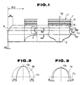
- a piston 1 of the type as mentioned above there is shown a piston 1 of the type as mentioned above. It is to be noted that a difference of dimension between portions of the piston 1 is exaggeratedly indicated in Figs. 6 - 8, in spite of a considerably small difference thereof in reality.
- the piston 1 includes a top 7 with a plurality of piston ring grooves 5, and a skirt 2 which is formed with a piston pin hole 3.
- the skirt 2 has a cross section in the shape of an ellipse which has two foci on a piston center plane O8 which is perpendicular to an axis or a center line O7 of the piston pin hole 3, and passes through a piston axis (no numeral).
- the outline of the skirt 2, which resembles a barrel, is obtained by changing a major axis of each of two ellipses X1 and Y1 in an axial direction of the piston 1.
- the skirt 2 is formed with a curved surface 4 on both sides which correspond to a direction perpendicular to a direction of the axis O7 of the piston pin hole 3.
- a distance between the piston axis and the curved surface 4 is shorter than a half of a reference diameter ⁇ D (phi D), i.e., a radius of the piston 1, by a1.
- a distance between the piston axis and the curved surface 4 is shorter than the above-mentioned radius by a1′ (a1′ ⁇ a1).
- the outline of the skirt 2 is variable, according to a position at which the cross section is taken, as shown in Figs. 7 and 8. Further, a length of the piston pin hole 3 is shorter by 2 x b1 in a direction of the axis O7 of the piston pin hole 3 than in a direction perpendicular thereto.
- U. S. Patent 4,535, 682 discloses a piston which has a skirt which includes two portions which are urged towards an associated cylinder during the various strokes of the working cycle. Each portion is provided with a bearing surface or surfaces for sliding engagement with the associated cylinder during reciprocation, thus reducing contact area of the skirt with the associated cylinder.
- a problem encountered in the skirt 2 of the piston 1 disclosed in JP-A 61-81558 is such that:
- contact area of the skirt 2 with a cylinder bore is relatively great as illustrated by a pattern C in Fig. 9, resulting in increased friction between the skirt 2 and the cylinder bore. If the above-mentioned contact area is reduced so as to eliminate such inconvenience, the operating position of the piston 1 becomes unstable, resulting in occurrence of hammering due to piston slapping.
- a piston which has reduced contact area of a skirt with a cylinder bore, and stabilizes the operating position of the piston.
- the present invention provides a piston for an internal combustion engine, comprising: a top portion; and a skirt portion formed with a piston pin hole, said skirt portion including first and second portions in an axial direction of the piston, said first portion being defined by one end of the skirt portion adjacent to said top portion and an imaginary axis of said piston pin hole, said second portion being defined by said imaginary axis of said piston pin hole and the other end of said skirt portion, said first portion having a first cross section formed in accordance with a first ellipse, said second portion having a second cross section formed in accordance with a second ellipse, said first and second ellipses having two foci on an imaginary center plane of the piston, respectively, said imaginary center plane being perpendicular to said imaginary axis of said piston pin hole, said first ellipse being smaller in ellipticity than said second ellipse, said skirt portion including a ramp portion connecting said first portion to said second portion.
- FIGs. 1 - 5 there is shown a first preferred embodiment of the present invention.
- the piston 1 in a manner similar to the prior art as described hereinbefore, includes a top 7 with a plurality of piston ring grooves 5, and a skirt 2 which is formed with a piston pin hole 3.
- the skirt 2 has a cross section in the shape of an ellipse which has two foci on a piston center plane O8 which is perpendicular to an axis or a center line O7 of the piston pin hole 3, and passes through a piston axis (no numeral).
- the outline of the skirt 2, which resembles a barrel, is obtained by changing a major axis of each of two ellipses X2 and Y2 in an axial direction of the piston 1, and the skirt 2 is formed with a curved surface 4 on both sides which correspond to a direction perpendicular to the direction of the axis O7 of the piston pin hole 3. It is to be noted that a2 > a2′ in Fig. 1.
- the ellipses X2 and Y2 are different in ellipticity. That is, the skirt 2 is so formed as to have smaller ellipticity in a portion higher than the axis O7 of the piston pin hole 3, and greater ellipticity in a portion lower than the axis O7, and is constructed so that the portion with smaller ellipticity is smoothly connected to the portion with greater ellipticity.
- the skirt 2 has a cross section in the shape of the ellipse Y2 as shown in Fig. 3.
- the skirt 2 has a cross section in the shape of the ellipse X2 as shown in Fig. 2.
- the ellipse X2 has greater difference between the major and minor axes, i.e., greater ellipticity, than the ellipse Y2 has (b2 > c2).
- the skirt 2 is so formed as to have the ellipse Y2 as shown in Fig. 3 in a portion higher than the position which is h1 distant upward from the axis O7 of the piston pin hole 3, and the ellipse X2 as shown in Fig. 2 in a portion lower than the position which is h1 distant downward from the axis O7 of the piston pin hole 3, and is constructed so that the upper portion is smoothly connected to the lower portion.
- a position which is h2 distant downward from the axis O7 of the piston pin hole 3 corresponds to a position of a reference diameter ⁇ D (phi D) of the piston 1.
- the skirt 2 has the ellipse Y2 with smaller ellipticity, so that it comes in contact with the cylinder bore 8 in relatively large area.
- the skirt 2 has the ellipse X2 with larger ellipticity, so that the skirt 2 comes in contact with the cylinder bore 8 only in small area.
- a share of the load will be considered with respect to the portion higher than the axis O7 of the piston pin 3 and the portion lower than the axis O7. Since the upper portion to the lower portion is in the ratio of load share 6 : 4, the area of the upper portion should be greater than the same of the lower portion so as to allow contact with the cylinder bore 8 with the same surface pressure. It is to be noted that the ratio of load share as mentioned above is estimated from the state of abrasion of the skirt 2. Therefore, it is desirable to have a contact area in the pattern D as shown in Fig. 4 so as to achieve lower friction.
- the ellipses X2 and Y2 may be different in ellipticity. That is, the skirt 2 may be so formed as to have smaller ellipticity in the portion higher than the axis O7 of the piston pin hole 3, and greater ellipticity in the portion lower than the axis O7.
- a contact position of the skirt 2 with the ellipses X2 and Y2 may be variable according to each value of a2 and a2′ as indicated in Fig. 1.
- each value of a2 and a2′ as indicated in Fig. 1, b2 as indicated in Fig. 2, and c2 as indicated in Fig. 3 is determined in consideration of thermal expansion of the skirt 2. Further, each value of h1 and h2 as indicated in Fig. 1 is determined in consideration of dimension of each portion of the piston 1.
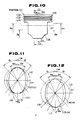
- FIGs. 10 - 17 there is shown a second preferred embodiment of the present invention.
- a piston 101 includes a top 105 with two piston ring grooves 102 and 103, and an oil ring groove 104, and a skirt 106 which is formed with a piston pin hole 107 (not shown in Fig. 10).
- the skirt 106 slidably comes in contact with a cylinder bore 110 (not shown in Fig. 10), thus controlling an operating position of the piston 101.
- a reference numeral O7 designates an axis or a center line of the piston pin hole 107
- O8 designates a piston center plane which is perpendicular to the center line O7, and passes through a piston axis (no numeral).
- the skirt 106 has a cross section in the shape of an ellipse which has two foci on the piston center plane O8.
- the ellipse is slightly changed in ellipticity from the lower portion to the upper portion of the skirt 106, and at least in both side portions thereof which correspond to a direction perpendicular to a direction of the center line O7 of the piston pin hole 107.
- the ellipticity represents a ratio of a minor axis to a major axis of the ellipse, i.e., as the ellipse becomes smaller in ellipticity, it becomes more nearly round.
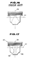
- the cross section is formed by integrating two elliptic arcs 111 and 112, and a straight line 116. Specifically, this cross section is formed in the range of an angle ⁇ 1 (theta 1) on both sides of the piston center plane O8.
- each of thrust and counter thrust sides which corresponds to the range of an angle ⁇ 2 (theta 2) on both sides of the piston center plane O8, the cross section is formed in accordance with the elliptic arc 111 which has a relatively small ellipticity V1, whereas in the side portion other than the above-mentioned portion, it is formed in accordance with the elliptic arc 112 which has a relatively large ellipticity V2, and the straight line 116 which connects the two arcs 111 and 112.
- the straight line 116 intersects a tangent 115 of the elliptic arc 112 with an angle ⁇ 5 (theta 5) so as to allow gradual change from the arc 111 to the arc 112. It is to be noted that 0.3° ⁇ ⁇ 5 ⁇ 2°.
- the cross section is formed by integrating two elliptic arcs 113 and 114, and a straight line 118.
- this cross section is formed in accordance with the elliptic arc 113 which has a relatively large ellipticity V3, whereas in the side portion other than the above-mentioned portion, it is formed in accordance with the elliptic arc 114 which has a relatively small ellipticity V4, and the straight line 118 which connects the two arcs 113 and 114.
- the straight line 118 intersects a tangent 117 of the elliptic arc 113 with an angle ⁇ 6 (theta 6) so as to allow gradual change from the arc 113 to the arc 114. It is to be noted that 0.3° ⁇ ⁇ 6 ⁇ 2°.
- Each of the ellipticities V1 - V4 is set to satisfy the conditions of V1 ⁇ V3 and V2 ⁇ V4.
- the skirt 106 becomes more nearly round from the lower portion to the upper portion. With a clearance between the skirt 106 and the cylinder bore 110 during engine operation, it is set to be 0 - 25 ⁇ m between the thrust portion formed in accordance with the elliptic arcs 112 and 114, and the cylinder bore 110, and greater than 25 ⁇ m between the side portion formed in accordance with the elliptic arcs 112 and 114, and the cylinder bore 110.
- the skirt 106 has a small difference in ellipticity between the arcs 112 and 114 in each of the side portions, and to have a large difference in ellipticity between the arcs 111 and 113 in the center portion.
- Each of the angles ⁇ 1 (theta 1) - ⁇ 3 (theta 3) is set to satisfy the conditions of ⁇ 3 ⁇ ⁇ 2 ⁇ ⁇ 1 so as to increase a contact area of the upper portion of the skirt 106 with the cylinder bore 110.
- the skirt 106 is shaped like a barrel, i.e., it has an axial outline having a curved surface 119 which is curved inward in the upper and lower portions thereof.
- the skirt 106 has a linear portion both between the center portion formed in accordance with the elliptic arcs 111 and 113, and the curved surface 119, and between the side portion formed with the elliptic arcs 112 and 114, and the curved surface 119.
- This linear portion is formed in accordance with a straight line 121 which forms an angle of ⁇ 4 (theta 4) with a tangent 120 which touches the curved surface 119 at the maximal diameter portion thereof being E E distant downward from the center line O7 of the piston pin hole 107.
- the ellipticity of each of the elliptic arcs 111 and 113, and 112 and 114 is set to satisfy the conditions of 0° ⁇ ⁇ 4 ⁇ 1°, thus achieving a small difference in ellipticity between the arcs 111 and 113, and 112 and 114 in an axial direction of the skirt 106.
- the skirt 106 has a taper amount X X (distance between the skirt 106 and the cylinder bore 110) which is larger in the lower end thereof, thus preventing scuffing of the skirt 106.
- the piston 101 reciprocates in the cylinder bore 110, and rotates a crankshaft (not shown) through a connecting rod 109.
- a resultant F gg of the combustion pressure P gg is divided into a force F cc in an axial direction of the connecting rod 109, and a force (side pressure) F tt which is perpendicular to the piston axis.
- the skirt 106 is thrust on the cylinder bore 110 by a higher pressure due to combustion pressure P gg and inertia force of the piston 101.
- the skirt 106 has a cross section in the shape of an ellipse having a major axis which is perpendicular to the center line O7 of the piston pin hole 107.
- the skirt 106 becomes more nearly round due to thermal expansion thereof, resulting in increased contact area with the cylinder bore 110. This allows an appropriate control of an operating position of the piston 101.
- the skirt 106 if the skirt 106 is formed with a constant ellipticity in the upper and lower portions hereof in a manner similar to the prior art, the skirt 106 has a greater contact area with the cylinder bore 110 in the lower portion thereof which is subjected to a low load, as indicated by a pattern surrounded by a dotted line.
- the cross section thereof decreases in ellipticity from V3 to V1 or becomes more nearly round from the lower portion to the upper portion, and it increases in the range of angle from ⁇ 3 (theta 3) to ⁇ 2 (theta 2).
- the skirt 106 comes in contact with the cylinder bore 110 along the center line O7 of the piston pin hole 107 and the piston center surface O8, thus forming a T-shaped contact zone 122 as indicated by a pattern surrounded by a dotted line in Fig. 17.
- the skirt 106 is thrust on the cylinder bore 110 by a higher pressure or load due to combustion pressure P gg and inertia force of the piston 101.
- the skirt 106 becomes more nearly round so that the skirt 106 comes in contact with the cylinder bore 110 in a wide area in a circumferential direction thereof, thus sufficiently reducing the surface pressure on the skirt 106, resulting in prevention of seizing.
- the cross section thereof increases in ellipticity so that the skirt 106 comes in contact with the cylinder bore 110 in a narrow area in the circumferential direction thereof, thus reducing friction loss of the piston 101. Further, in a zone other than the T-shaped contact zone 122, the skirt 106 keeps a clearance of more than 25 ⁇ m with the cylinder bore 110, thus reducing the friction force F due to oil dragging.
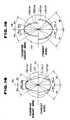
- the skirt 106 has a cross section which is asymmetrical on the thrust side and the counter thrust side. or has two different ellipticities.
- the cross section has the range of an angle ⁇ 1 (theta 1) on the thrust side, which is larger than the range of an angle ⁇ 11 (theta 11) on the counter thrust side.
- the cross section is formed by integrating an elliptic arc 111 with an ellipticity V1 in a portion thereof which corresponds to the range of an angle ⁇ 2 (theta 2). and an elliptic arc 112 with a relatively large ellipticity V2 in the side portion other than the above-mentioned portion.
- the cross section is formed by integrating an elliptic arc 131 with an ellipticity V11 (V11 > V1) in a portion thereof which corresponds to the range of an angle ⁇ 12 (theta 12) ( ⁇ 12 ⁇ ⁇ 2), and an elliptic arc 132 with a relatively large ellipticity V12 (V12 > V2) in the side portion other than the above-mentioned portion.
- the cross section in the portion of the skirt 106 lower than the center line O7 of the piston pin hole 107, the cross section also has the range of the angle ⁇ 1 (theta 1) on the thrust side, which is larger than the range of the angle ⁇ 11 (theta 11) on the counter thrust side.
- the cross section On the thrust side, the cross section is formed by integrating an elliptic arc 113 with an ell ipticity V3 (V3 ⁇ V1) in a portion thereof which corresponds to the range of an angle ⁇ 3 (theta 3), and an elliptic arc 114 with a relatively large ellipticity V4 (V4 ⁇ V2) in the side portion other than the above-mentioned portion.
- the cross section is formed by integrating an elliptic arc 133 with an ellipticity V13 (V13 > V3 and V13 ⁇ V11) in a portion thereof which corresponds to the range of an angle ⁇ 13 (theta 13) ( ⁇ 13 ⁇ ⁇ 13), and an elliptic arc 132 with a relatively large ellipticity V14 (V14 > V4 and V14 ⁇ V12) in the side portion other than the above-mentioned portion.
- the skirt 106 Since the skirt 106 is thrust on a cylinder bore 110 principally by an inertia force thereof on the counter thrust side, whereas the skirt 106 is thrusted thereon by a combustion pressure P gg on the thrust side, the skirt 106 is subjected to a smaller load on the counter thrust side. In this situation, the skirt 106 comes in contact with the cylinder bore 110 in a reduced T-shaped zone as indicated by a pattern surrounded by a dotted line in Fig. 20, thus further decreasing friction loss of the piston 101.
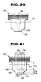
- a fourth preferred embodiment of the present invention On both sides of the skirt 106 which correspond to a direction perpendicular to a direction of the center line O7 of the piston pin hole 107, the cross section thereof decreases in ellipticity from the lower portion to the upper portion. As a result, the skirt 106 comes in contact with the cylinder bore 110 along the center line O7 of the piston pin hole 107 and the piston center plane O8, thus forming a T-shaped contact zone 122 as indicated by a pattern surrounded by a dotted line in Fig. 21. Referring also to Figs.
- the skirt 106 is formed, in a circumferential direction thereof, with a plurality of grooves 143 which are changed in depth in the circumferential direction. Further, in the T-shaped contact zone are provided center and lower zones 141 and 142, each including the grooves 143 with relatively large opening.
- the depth of the groove 143 is largely changed from h10 to h11 in a predetermined proportion, and the opening thereof is increased from L b to L d , thus reducing a width of a beltlike surface 144 which exists between the grooves 143 from L a to L c .
Landscapes
- Engineering & Computer Science (AREA)
- Chemical & Material Sciences (AREA)
- Combustion & Propulsion (AREA)
- Mechanical Engineering (AREA)
- General Engineering & Computer Science (AREA)
- Pistons, Piston Rings, And Cylinders (AREA)
Applications Claiming Priority (6)
| Application Number | Priority Date | Filing Date | Title |
|---|---|---|---|
| JP250527/89 | 1989-09-28 | ||
| JP25052789 | 1989-09-28 | ||
| JP1250527A JP2598326B2 (ja) | 1989-09-28 | 1989-09-28 | 内燃機関用ピストン |
| JP1335753A JP2588289B2 (ja) | 1989-12-25 | 1989-12-25 | 内燃機関のピストン |
| JP335753/89 | 1989-12-25 | ||
| JP33575389 | 1989-12-25 |
Publications (3)
| Publication Number | Publication Date |
|---|---|
| EP0420618A1 true EP0420618A1 (de) | 1991-04-03 |
| EP0420618B1 EP0420618B1 (de) | 1993-03-31 |
| EP0420618B2 EP0420618B2 (de) | 2000-03-29 |
Family
ID=26539805
Family Applications (1)
| Application Number | Title | Priority Date | Filing Date |
|---|---|---|---|
| EP90310546A Expired - Lifetime EP0420618B2 (de) | 1989-09-28 | 1990-09-26 | Kolben für eine Brennkraftmaschine |
Country Status (3)
| Country | Link |
|---|---|
| US (1) | US5107807A (de) |
| EP (1) | EP0420618B2 (de) |
| DE (1) | DE69001229T3 (de) |
Cited By (4)
| Publication number | Priority date | Publication date | Assignee | Title |
|---|---|---|---|---|
| US5211101A (en) * | 1990-06-22 | 1993-05-18 | Mahle Gmbh | Piston with oval shaped lands |
| EP0752525A1 (de) * | 1995-07-07 | 1997-01-08 | Isuzu Motors Limited | Kolben |
| WO2000025012A1 (de) * | 1998-10-22 | 2000-05-04 | Peter Greiner | Kohlenstoffkolben für eine brennkraftmaschine |
| DE112012003224B4 (de) | 2011-08-04 | 2023-02-09 | Caterpillar Inc. | Kolben für einen Verbrennungsmotor und Verfahren dafür |
Families Citing this family (11)
| Publication number | Priority date | Publication date | Assignee | Title |
|---|---|---|---|---|
| US5172626A (en) * | 1991-08-22 | 1992-12-22 | General Motors Corporation | Stabilized piston skirt having varying peaks and concave surfaces |
| JP3078414B2 (ja) * | 1992-12-14 | 2000-08-21 | 株式会社ユニシアジェックス | 内燃機関のピストン |
| JPH06257507A (ja) * | 1993-03-09 | 1994-09-13 | Nissan Motor Co Ltd | 内燃機関のピストン |
| US5476076A (en) * | 1994-12-06 | 1995-12-19 | Zhou; Zhishan | Internal combustion piston engine utilizing interference movable fit technology |
| KR960043524A (ko) * | 1995-05-23 | 1996-12-23 | 홍-치우 후 | 출력 버퍼링 장치 |
| RU2257484C1 (ru) * | 2004-02-16 | 2005-07-27 | Южно-Уральский государственный университет | Трибосопряжение поршень - цилиндр двигателя внутреннего сгорания |
| US20060027095A1 (en) * | 2004-08-02 | 2006-02-09 | Miller Andrew J | Piston having centered pin hole and skirt profile |
| GB2448544B (en) * | 2007-04-20 | 2011-09-21 | Ford Global Tech Llc | Piston skirt design |
| DE102008029071B4 (de) * | 2008-06-10 | 2019-12-24 | Dr. Ing. H.C. F. Porsche Aktiengesellschaft | Kolben für eine Brennkraftmaschine |
| DE102010015568A1 (de) * | 2010-04-19 | 2011-10-20 | Ks Kolbenschmidt Gmbh | Kolbenoberteil eines gebauten oder geschweißten Kolbens mit erweiterten Kühlräumen |
| JP6299949B2 (ja) * | 2013-10-31 | 2018-03-28 | スズキ株式会社 | 内燃機関用ピストン |
Citations (4)
| Publication number | Priority date | Publication date | Assignee | Title |
|---|---|---|---|---|
| DE1475846A1 (de) * | 1965-01-12 | 1969-06-12 | Schmidt Gmbh Karl | Kolben,insbesondere fuer Verbrennungskraftmaschinen |
| DE3022858A1 (de) * | 1980-06-19 | 1981-12-24 | Mahle Gmbh, 7000 Stuttgart | Kolben fuer verbrennungsmotoren |
| EP0211189A2 (de) * | 1985-07-27 | 1987-02-25 | Mahle Gmbh | Tauchkolben, insbesondere für Verbrennungsmotoren |
| WO1988008078A1 (en) * | 1987-04-18 | 1988-10-20 | Mahle Gmbh | Light-metal trunk piston for internal combustion engines |
Family Cites Families (16)
| Publication number | Priority date | Publication date | Assignee | Title |
|---|---|---|---|---|
| US2046789A (en) * | 1933-08-01 | 1936-07-07 | Cleveland Trust Co | Piston |
| US2136162A (en) * | 1935-01-30 | 1938-11-08 | Packard Motor Car Co | Internal combustion engine |
| US2120019A (en) * | 1935-11-27 | 1938-06-07 | Cleveland Trust Co | Piston |
| US2217542A (en) * | 1938-01-17 | 1940-10-08 | Sterling Corp | Piston |
| US2513814A (en) * | 1947-01-21 | 1950-07-04 | Aluminum Co Of America | Piston |
| JPS5781143A (en) * | 1980-11-07 | 1982-05-21 | Fuji Heavy Ind Ltd | Piston for internal combustion engine |
| ZA825602B (en) * | 1981-08-11 | 1984-03-28 | Ae Plc | Pistons |
| JPS58180353U (ja) * | 1982-05-27 | 1983-12-02 | 日産自動車株式会社 | 内燃機関のピストン |
| DE3418454A1 (de) * | 1984-05-18 | 1985-12-19 | Kolbenschmidt AG, 7107 Neckarsulm | Leichtmetallkolben |
| JPS613947A (ja) * | 1984-06-19 | 1986-01-09 | Sanden Corp | 給湯機の制御装置 |
| JPS618558A (ja) * | 1984-06-25 | 1986-01-16 | Matsushita Electric Ind Co Ltd | ヒ−トポンプ給湯装置 |
| JPS6181558A (ja) * | 1984-09-27 | 1986-04-25 | Honda Motor Co Ltd | 内燃機関用ピストン |
| IT1182507B (it) * | 1985-07-12 | 1987-10-05 | Ae Borgo Spa | Pistoni con profilo asimmetrico per motori a combustione interna |
| DE3531801A1 (de) * | 1985-09-06 | 1987-03-19 | Kolbenschmidt Ag | Leichtmetallkolben |
| JPS6321352A (ja) * | 1986-07-11 | 1988-01-28 | エイイ−・ピ−エルシ− | ピストン |
| JPH0310057U (de) * | 1989-06-20 | 1991-01-30 |
-
1990
- 1990-09-11 US US07/580,544 patent/US5107807A/en not_active Expired - Lifetime
- 1990-09-26 EP EP90310546A patent/EP0420618B2/de not_active Expired - Lifetime
- 1990-09-26 DE DE69001229T patent/DE69001229T3/de not_active Expired - Lifetime
Patent Citations (4)
| Publication number | Priority date | Publication date | Assignee | Title |
|---|---|---|---|---|
| DE1475846A1 (de) * | 1965-01-12 | 1969-06-12 | Schmidt Gmbh Karl | Kolben,insbesondere fuer Verbrennungskraftmaschinen |
| DE3022858A1 (de) * | 1980-06-19 | 1981-12-24 | Mahle Gmbh, 7000 Stuttgart | Kolben fuer verbrennungsmotoren |
| EP0211189A2 (de) * | 1985-07-27 | 1987-02-25 | Mahle Gmbh | Tauchkolben, insbesondere für Verbrennungsmotoren |
| WO1988008078A1 (en) * | 1987-04-18 | 1988-10-20 | Mahle Gmbh | Light-metal trunk piston for internal combustion engines |
Cited By (6)
| Publication number | Priority date | Publication date | Assignee | Title |
|---|---|---|---|---|
| US5211101A (en) * | 1990-06-22 | 1993-05-18 | Mahle Gmbh | Piston with oval shaped lands |
| EP0752525A1 (de) * | 1995-07-07 | 1997-01-08 | Isuzu Motors Limited | Kolben |
| US5682808A (en) * | 1995-07-07 | 1997-11-04 | Isuzu Motors Limited | Piston with a diametric reduction of a skirt portion greater on the thrust side, than that on the counter-thrust side |
| WO2000025012A1 (de) * | 1998-10-22 | 2000-05-04 | Peter Greiner | Kohlenstoffkolben für eine brennkraftmaschine |
| US6883418B1 (en) | 1998-10-22 | 2005-04-26 | Peter Greiner | Carbon piston for an internal combustion engine |
| DE112012003224B4 (de) | 2011-08-04 | 2023-02-09 | Caterpillar Inc. | Kolben für einen Verbrennungsmotor und Verfahren dafür |
Also Published As
| Publication number | Publication date |
|---|---|
| US5107807A (en) | 1992-04-28 |
| EP0420618B2 (de) | 2000-03-29 |
| EP0420618B1 (de) | 1993-03-31 |
| DE69001229D1 (de) | 1993-05-06 |
| DE69001229T2 (de) | 1993-07-08 |
| DE69001229T3 (de) | 2000-08-24 |
Similar Documents
| Publication | Publication Date | Title |
|---|---|---|
| EP0420618A1 (de) | Kolben für eine Brennkraftmaschine | |
| EP1231393B1 (de) | Gleitelement mit niedriger Reibung für eine hin-und hergehende Maschine | |
| US6739238B2 (en) | Sliding structure for a reciprocating internal combustion engine and a reciprocating internal combustion engine using the sliding structure | |
| EP2521865B1 (de) | Profilierte pleuelstangenbohrung mit mikrovertiefungen | |
| EP1111225B1 (de) | Gleitelement und kolben für brennkraftmaschine | |
| EP0071361B2 (de) | Kolben für eine Brennkraftmaschine | |
| US5172626A (en) | Stabilized piston skirt having varying peaks and concave surfaces | |
| EP0368004A1 (de) | Kolben | |
| JP7254836B2 (ja) | 組合せオイルリング | |
| JP6876766B2 (ja) | 半割軸受およびすべり軸受 | |
| EP3572680B1 (de) | Halblager und gleitlager | |
| GB2145945A (en) | The manufacture of pistons | |
| GB2171776A (en) | Pistons | |
| EP0171221B2 (de) | Kolben für Brennkraftmaschinen | |
| EP3115654B1 (de) | Zur verringerung der reibung konfigurierter kolbenring | |
| EP0411913B2 (de) | Kolbenzusammenbau für eine Brennkraftmaschine | |
| EP0251393B1 (de) | Kolben | |
| US6041749A (en) | Wear resistant cylinder barrel surface for supporting a piston | |
| US4230027A (en) | Reciprocating piston | |
| JPH06257507A (ja) | 内燃機関のピストン | |
| JP2697321B2 (ja) | 内燃機関のピストン | |
| EP4450795B1 (de) | Kolbenring | |
| KR20230029553A (ko) | 반할 베어링 및 슬라이딩 베어링 | |
| JP2588289B2 (ja) | 内燃機関のピストン | |
| JPS591083Y2 (ja) | ピストン |
Legal Events
| Date | Code | Title | Description |
|---|---|---|---|
| PUAI | Public reference made under article 153(3) epc to a published international application that has entered the european phase |
Free format text: ORIGINAL CODE: 0009012 |
|
| 17P | Request for examination filed |
Effective date: 19901012 |
|
| AK | Designated contracting states |
Kind code of ref document: A1 Designated state(s): DE GB |
|
| 17Q | First examination report despatched |
Effective date: 19910903 |
|
| GRAA | (expected) grant |
Free format text: ORIGINAL CODE: 0009210 |
|
| AK | Designated contracting states |
Kind code of ref document: B1 Designated state(s): DE GB |
|
| REF | Corresponds to: |
Ref document number: 69001229 Country of ref document: DE Date of ref document: 19930506 |
|
| PLBI | Opposition filed |
Free format text: ORIGINAL CODE: 0009260 |
|
| 26 | Opposition filed |
Opponent name: ALCAN DEUTSCHLAND GMBH Effective date: 19931223 Opponent name: MAHLE GMBH Effective date: 19931224 |
|
| APCC | Communication from the board of appeal sent |
Free format text: ORIGINAL CODE: EPIDOS OBAPO |
|
| APCC | Communication from the board of appeal sent |
Free format text: ORIGINAL CODE: EPIDOS OBAPO |
|
| APAC | Appeal dossier modified |
Free format text: ORIGINAL CODE: EPIDOS NOAPO |
|
| PLAW | Interlocutory decision in opposition |
Free format text: ORIGINAL CODE: EPIDOS IDOP |
|
| PLAW | Interlocutory decision in opposition |
Free format text: ORIGINAL CODE: EPIDOS IDOP |
|
| PUAH | Patent maintained in amended form |
Free format text: ORIGINAL CODE: 0009272 |
|
| STAA | Information on the status of an ep patent application or granted ep patent |
Free format text: STATUS: PATENT MAINTAINED AS AMENDED |
|
| 27A | Patent maintained in amended form |
Effective date: 20000329 |
|
| AK | Designated contracting states |
Kind code of ref document: B2 Designated state(s): DE GB |
|
| EN | Fr: translation not filed | ||
| REG | Reference to a national code |
Ref country code: GB Ref legal event code: IF02 |
|
| APAH | Appeal reference modified |
Free format text: ORIGINAL CODE: EPIDOSCREFNO |
|
| REG | Reference to a national code |
Ref country code: GB Ref legal event code: 746 Effective date: 20070629 |
|
| PGFP | Annual fee paid to national office [announced via postgrant information from national office to epo] |
Ref country code: GB Payment date: 20090923 Year of fee payment: 20 |
|
| PGFP | Annual fee paid to national office [announced via postgrant information from national office to epo] |
Ref country code: DE Payment date: 20090923 Year of fee payment: 20 |
|
| REG | Reference to a national code |
Ref country code: GB Ref legal event code: PE20 Expiry date: 20100925 |
|
| PG25 | Lapsed in a contracting state [announced via postgrant information from national office to epo] |
Ref country code: GB Free format text: LAPSE BECAUSE OF EXPIRATION OF PROTECTION Effective date: 20100925 |
|
| PG25 | Lapsed in a contracting state [announced via postgrant information from national office to epo] |
Ref country code: DE Free format text: LAPSE BECAUSE OF EXPIRATION OF PROTECTION Effective date: 20100926 |