EP0420656B1 - Verfahren und Vorrichtung für die Zweiphasen-Vakuumextraktion von Bodenverunreinigungen - Google Patents
Verfahren und Vorrichtung für die Zweiphasen-Vakuumextraktion von Bodenverunreinigungen Download PDFInfo
- Publication number
- EP0420656B1 EP0420656B1 EP90310620A EP90310620A EP0420656B1 EP 0420656 B1 EP0420656 B1 EP 0420656B1 EP 90310620 A EP90310620 A EP 90310620A EP 90310620 A EP90310620 A EP 90310620A EP 0420656 B1 EP0420656 B1 EP 0420656B1
- Authority
- EP
- European Patent Office
- Prior art keywords
- liquid
- stream
- well
- accordance
- water table
- Prior art date
- Legal status (The legal status is an assumption and is not a legal conclusion. Google has not performed a legal analysis and makes no representation as to the accuracy of the status listed.)
- Expired - Lifetime
Links
- 238000000605 extraction Methods 0.000 title claims description 48
- 239000000356 contaminant Substances 0.000 title claims description 34
- 238000000034 method Methods 0.000 title claims description 22
- 230000008569 process Effects 0.000 title claims description 15
- 239000002689 soil Substances 0.000 title description 23
- XLYOFNOQVPJJNP-UHFFFAOYSA-N water Substances O XLYOFNOQVPJJNP-UHFFFAOYSA-N 0.000 claims description 56
- 239000007788 liquid Substances 0.000 claims description 42
- 239000007789 gas Substances 0.000 claims description 15
- 239000012530 fluid Substances 0.000 claims description 9
- 238000000926 separation method Methods 0.000 claims description 5
- 238000002347 injection Methods 0.000 claims description 4
- 239000007924 injection Substances 0.000 claims description 4
- 238000004891 communication Methods 0.000 claims description 3
- 238000002156 mixing Methods 0.000 claims description 3
- 239000000203 mixture Substances 0.000 claims description 3
- 239000007787 solid Substances 0.000 claims 2
- 239000000284 extract Substances 0.000 claims 1
- 239000012071 phase Substances 0.000 description 19
- 239000003673 groundwater Substances 0.000 description 15
- 239000007791 liquid phase Substances 0.000 description 10
- 238000012545 processing Methods 0.000 description 8
- 239000008239 natural water Substances 0.000 description 7
- 239000012808 vapor phase Substances 0.000 description 7
- 238000012216 screening Methods 0.000 description 5
- 239000002680 soil gas Substances 0.000 description 5
- 239000012855 volatile organic compound Substances 0.000 description 5
- OKTJSMMVPCPJKN-UHFFFAOYSA-N Carbon Chemical compound [C] OKTJSMMVPCPJKN-UHFFFAOYSA-N 0.000 description 4
- 230000008901 benefit Effects 0.000 description 4
- 239000000463 material Substances 0.000 description 4
- 229910000278 bentonite Inorganic materials 0.000 description 3
- 239000000440 bentonite Substances 0.000 description 3
- SVPXDRXYRYOSEX-UHFFFAOYSA-N bentoquatam Chemical compound O.O=[Si]=O.O=[Al]O[Al]=O SVPXDRXYRYOSEX-UHFFFAOYSA-N 0.000 description 3
- 238000001914 filtration Methods 0.000 description 3
- 238000009434 installation Methods 0.000 description 3
- 238000005086 pumping Methods 0.000 description 3
- 230000009467 reduction Effects 0.000 description 3
- WSLDOOZREJYCGB-UHFFFAOYSA-N 1,2-Dichloroethane Chemical compound ClCCCl WSLDOOZREJYCGB-UHFFFAOYSA-N 0.000 description 2
- 239000004568 cement Substances 0.000 description 2
- 230000000694 effects Effects 0.000 description 2
- 239000011440 grout Substances 0.000 description 2
- 238000004519 manufacturing process Methods 0.000 description 2
- 230000035699 permeability Effects 0.000 description 2
- 230000004044 response Effects 0.000 description 2
- 239000004576 sand Substances 0.000 description 2
- 239000000126 substance Substances 0.000 description 2
- 238000012546 transfer Methods 0.000 description 2
- 239000004215 Carbon black (E152) Substances 0.000 description 1
- 239000004677 Nylon Substances 0.000 description 1
- QVGXLLKOCUKJST-UHFFFAOYSA-N atomic oxygen Chemical compound [O] QVGXLLKOCUKJST-UHFFFAOYSA-N 0.000 description 1
- 238000009412 basement excavation Methods 0.000 description 1
- 230000009286 beneficial effect Effects 0.000 description 1
- 230000015572 biosynthetic process Effects 0.000 description 1
- 238000004140 cleaning Methods 0.000 description 1
- 150000001875 compounds Chemical class 0.000 description 1
- 238000011109 contamination Methods 0.000 description 1
- 238000005260 corrosion Methods 0.000 description 1
- 230000007797 corrosion Effects 0.000 description 1
- 230000006378 damage Effects 0.000 description 1
- 238000005202 decontamination Methods 0.000 description 1
- 230000003588 decontaminative effect Effects 0.000 description 1
- 238000013461 design Methods 0.000 description 1
- 238000007599 discharging Methods 0.000 description 1
- 230000007613 environmental effect Effects 0.000 description 1
- 230000003628 erosive effect Effects 0.000 description 1
- 238000005189 flocculation Methods 0.000 description 1
- 230000016615 flocculation Effects 0.000 description 1
- 238000005755 formation reaction Methods 0.000 description 1
- 239000007792 gaseous phase Substances 0.000 description 1
- 229930195733 hydrocarbon Natural products 0.000 description 1
- 150000002430 hydrocarbons Chemical class 0.000 description 1
- 230000006872 improvement Effects 0.000 description 1
- 238000011065 in-situ storage Methods 0.000 description 1
- 238000011068 loading method Methods 0.000 description 1
- 230000007246 mechanism Effects 0.000 description 1
- 229910052751 metal Inorganic materials 0.000 description 1
- 239000002184 metal Substances 0.000 description 1
- 150000002739 metals Chemical class 0.000 description 1
- 229920001778 nylon Polymers 0.000 description 1
- 229910052760 oxygen Inorganic materials 0.000 description 1
- 239000001301 oxygen Substances 0.000 description 1
- 238000006213 oxygenation reaction Methods 0.000 description 1
- 238000001556 precipitation Methods 0.000 description 1
- 230000000750 progressive effect Effects 0.000 description 1
- 230000002035 prolonged effect Effects 0.000 description 1
- 238000000746 purification Methods 0.000 description 1
- 239000008213 purified water Substances 0.000 description 1
- 238000011084 recovery Methods 0.000 description 1
- 238000005067 remediation Methods 0.000 description 1
- 238000009877 rendering Methods 0.000 description 1
- 229920006395 saturated elastomer Polymers 0.000 description 1
- 238000009738 saturating Methods 0.000 description 1
- 238000005201 scrubbing Methods 0.000 description 1
- 238000004904 shortening Methods 0.000 description 1
- 239000002002 slurry Substances 0.000 description 1
- 238000005527 soil sampling Methods 0.000 description 1
- 239000000243 solution Substances 0.000 description 1
- 238000001179 sorption measurement Methods 0.000 description 1
- 230000003068 static effect Effects 0.000 description 1
- 238000010408 sweeping Methods 0.000 description 1
- 230000009466 transformation Effects 0.000 description 1
- 238000009834 vaporization Methods 0.000 description 1
- 230000008016 vaporization Effects 0.000 description 1
- 238000013022 venting Methods 0.000 description 1
- 239000002699 waste material Substances 0.000 description 1
Images

Classifications
-
- E—FIXED CONSTRUCTIONS
- E21—EARTH OR ROCK DRILLING; MINING
- E21B—EARTH OR ROCK DRILLING; OBTAINING OIL, GAS, WATER, SOLUBLE OR MELTABLE MATERIALS OR A SLURRY OF MINERALS FROM WELLS
- E21B43/00—Methods or apparatus for obtaining oil, gas, water, soluble or meltable materials or a slurry of minerals from wells
- E21B43/34—Arrangements for separating materials produced by the well
-
- B—PERFORMING OPERATIONS; TRANSPORTING
- B09—DISPOSAL OF SOLID WASTE; RECLAMATION OF CONTAMINATED SOIL
- B09C—RECLAMATION OF CONTAMINATED SOIL
- B09C1/00—Reclamation of contaminated soil
- B09C1/005—Extraction of vapours or gases using vacuum or venting
-
- E—FIXED CONSTRUCTIONS
- E21—EARTH OR ROCK DRILLING; MINING
- E21B—EARTH OR ROCK DRILLING; OBTAINING OIL, GAS, WATER, SOLUBLE OR MELTABLE MATERIALS OR A SLURRY OF MINERALS FROM WELLS
- E21B43/00—Methods or apparatus for obtaining oil, gas, water, soluble or meltable materials or a slurry of minerals from wells
- E21B43/12—Methods or apparatus for controlling the flow of the obtained fluid to or in wells
- E21B43/121—Lifting well fluids
Definitions
- This invention relates to a process and apparatus for removing contaminants from soil.
- Contaminants may exist in subsurface soil in the liquid or vapor phase as discrete substances and mixed with and/or dissolved in ground water and soil gases. Such contaminants may be found in the vadose (unsaturated) zone found between the surface of the earth and the water table, at the interface between the vadose zone and the water table, and in the saturated zone below the water table.
- soil and ground water are contaminated with suspended or water-soluble chemicals, or both.
- a variety of techniques have been used for removal of soil contaminants and remediation of affected soil.
- One common technique involves the excavation and off-site treatment of the soil.
- Another technique involves saturating the contaminated soil and water in situ , causing the contaminants to be slowly leached from the soil by the water. The contaminated water can then be removed.
- DE-A-3,739,126 describes a method for decontamination of an area of ground contaminated in particularly with oil or oil - or hydrocarbon - containing material. At least one shaft is dug in the vadose zone via which a liquid, such as ground water and/or a cleaning gas, present in the contaminated ground and loaded with contaminated material, can be drawn off and subsequently cleaned.
- a liquid such as ground water and/or a cleaning gas
- the present invention involves a process and apparatus for two phase removal of contaminants from the soil according to appended claims 1 and 7.
- the process involves the steps of providing a borehole in the contaminated area; placing in the borehole a riser pipe, the riser pipe preferably being so constructed as to admit fluids both from the vadose zone and from below the natural water table; applying a vacuum to the riser pipe so as to draw soil gases and entrained liquid into the riser pipe and to transport both the gases and the liquid to the surface; separating the liquid and the gases, and separately subjecting the separated liquid and gases to appropriate treatment.
- Treated water may be returned to the soil or disposed of in conventional ways.
- the riser pipe is constructed with perforations (screening) extending below the natural water table and also upward into the unsaturated (vadose) zone.
- the unsaturated zone may be the natural vadose zone lying above the natural water table, or an expanded "artificial" vadose zone created when removal of the ground water through the extraction well causes local lowering of the water table. Placing of the screening so that it extends into the vadose zone allows soil gases, including contaminants in the vapor phase, to be drawn into the well under the influence of a vacuum generator. The gases, it has been found, entrain the liquid phase, so that both phases may be transported to the surface together in a common stream.
- the two phases are separated in a vapor-liquid disengaging vessel, such as a cyclone separator, knock-out pot or other suitable component, and after separation the phases may individually be routed to systems for contaminant removal by further treatment steps.
- a vapor-liquid disengaging vessel such as a cyclone separator, knock-out pot or other suitable component
- Suitable processes for contaminant removal include filtration, adsorption, air stripping, settling, flocculation, precipitation, scrubbing and the like.
- the treatment well may be constructed so that screening is at all times below the water table, even in the situation in which removal of water causes local depression of the water table.
- the fluid transported to the surface would predominantly be in the liquid phase, although vapor-liquid separation and individual phase treatment are still provided at the surface to deal with phase transformation which may occur as a result of turbulence and pressure reduction at the suction side of the vacuum device.
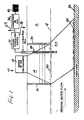
- FIG. 1 there is seen schematically a system, designated generally by the reference numeral 10, for two phase vacuum extraction and treatment of soil contaminants.
- Seen in Figure 1 is a source 12 of volatile contaminants, creating a plume 14 of absorbed or suspended contaminants in the soil 16 of the vadose (unsaturated) zone.
- the contaminants making up the plume 14 tend to leach or percolate downwardly toward the natural water table 18.
- Components lighter than water and not dissolved are depicted by the reference numeral 20, and tend to float at the top of the water table.
- Dissolved contaminants and free-phase contaminants lighter than water tend to percolate downwardly in a plume 22 below the water table 18, and free-phase components 24 heavier than water tend to migrate downwardly to the aquitard 26.
- An extraction well designated generally by the reference numeral 28, and which will be described in greater detail shortly, is sunk in the area of the plume 14 and extends through the vadose zone and below the natural water table 18.
- Air inlet wells designated by the reference numeral 30, which will also be described in greater detail. Air inlet wells 30, it will be understood, are best disposed at spaced locations around the perimeter of the plume 14. Those skilled in the art will appreciate that the number and spacing of the air inlet wells 30 with respect to the plume 14 and extraction well 28 will depend upon the size of the plume 14, as well as the composition and permeability of the soil to be treated.
- a vacuum extraction system Associated with the extraction well 28 is a vacuum extraction system, designated by the reference numeral 32. Gases removed by the vacuum extraction system 32 may be vented to atmosphere at 34 if within acceptable environmental limits, or further processed such as by being incinerated or passed to a condenser, granular activated carbon filter, or other such component 36.
- the component 36 serves to remove contaminants from the extracted gases. Water extracted by the process may be treated by passing it through conventional systems for metals removal, volatile organic compound removal, or other steps of purification. The treated and purified water, if it is of sufficient purity at this stage, may be returned to a sewer or directly to the ground as indicated at 38. Contaminants may be stored in drums 40 for eventual destruction or further processing.
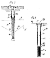
- the extraction well 28 in the illustrated form includes an elongated borehole 42, into which there is placed a riser pipe 44.
- the riser pipe 44 includes an imperforate upper portion 46 and a perforate (screened) lower portion 48.
- the riser pipe 44 is of four inch (10.2 cm) diameter PVC, capped at the bottom, and the screen consists of .010 inch (0.25 mm) slots.
- the riser pipe 44 is approximately twenty feet (6.1 m) in length, with the lower fifteen feet (4.6 m) comprising the slotted lower portion 48 and the upper five feet (1.5 m) the imperforate upper portion 46.
- the upper end of the riser pipe 44 is here shown to be associated with a concrete floor or deck, and is provided with a suitable pipe fitting 52, enabling the riser pipe 44 to be coupled in fluid communication to the remainder of the vacuum extraction system 32 (not seen in Figure 3).
- the upper portion 46 of the riser pipe 44 is surrounded by a low permeability grout, such as bentonite cement 54, and below the grout 54 by a bentonite seal 56.
- the area within the borehole 42 surrounding the slotted lower portion 48 of the riser pipe 44 and part of the upper portion 46 above the slotted lower portion 48 is packed with fine screened sand, to facilitate the flow of gas and liquid from the surrounding soil into the riser pipe 44.
- the extraction well 28 is constructed so that the screened lower portion 48 extends below the water table and also upwardly into the vadose zone.
- the vadose zone into which the screened lower portion 48 extends may be above the natural water table 18, or it may be the expanded artificial vadose zone created when prolonged removal of ground water through the extraction well causes local lowering of the water table as indicated by the reference numeral 18′ in Figure 3.
- Placement of the screened lower portion 48 of the riser pipe 44 as indicated above allows soil gases (the vapor phase) to be drawn into the well under the influence of Vacuum created by the extraction system 32 and to entrain the liquid phase so that both phases may be transported to the surface together.
- the two phases may be separated and differently treated.
- the extraction well 28 may be so constructed that the screening of the lower portion 48 is entirely submerged, i.e., disposed below the natural or actual water table, even after withdrawal of water from the aquifer under the influence of the vacuum extraction system 32. In the latter case, the fluid transported to the surface would be predominantly in the liquid phase.
- the air inlet well 30 comprises a borehole 58, which receives a pipe 60.
- the pipe 60 in one operative embodiment comprises a four inch (10.2 cm) diameter PVC pipe, capped at the bottom, and having a screen of .010 inch (0.25 mm) slots.
- the pipe 60 is surrounded at its upper end by a cement collar 62, extending to the ground surface 64. Suitable caps 66 and covers 68 may be provided in association with the collar 62 to selectively cap or cover the injection well as desired.
- a bentonite slurry 72 Surrounding a medial portion 70 of the pipe 60 within the borehole 58 is a bentonite slurry 72, which provides a gas-tight seal between the pipe 60 and the borehole 58.
- the slotted lower portion 74 of the pipe 60 is surrounded by gas-permeable packed sand 76.
- the pipe 60 facilitates the injection of air into the zone surrounding the plume 16.
- a vacuum pump 78 driven by electric motor 80, is in fluid communication through a pipe 82, knock-out pot 84 and pipe 86 with the extraction well 28.
- the knock-out pot 84 may be of conventional design, familiar to those skilled in the art.
- the knock-out pot 84 serves to separate the two phases emerging from the extraction well 28, enabling them to be subjected to appropriate further processing.
- a pipe 88 is provided in association with the knock-out pot 84, to conduct effluent in the liquid phase through filtration and stripping steps.
- Filtration is provided in the illustrated embodiment by parallel bag filters 90 and 92 which may alternately or simultaneously be used in a conventional manner. Cut-off valves, omitted in the drawings for clarity permit either filter 90, 92 to be isolated, and each bag removed, cleaned or replaced. Suitable pressure gauges, not shown may be placed on the suction and discharge sides of the bag filters 90 and 92 to indicate bag loading.
- the bag filters 90 and 92 were 50 micron nylon filters, sold by Rosedale Products, Incorporated, capable of passing 222 gpm at 150 psi. Other equivalent separation techniques and apparatus may be used.
- a pump 94 which, for erosion resistance, is preferably of the single stage progressive cavity (screw) type, serves to draw off the liquid phase effluent of the knock-out pot 84.
- One suitable pump is sold by the Nemo Pump Division of Netzsch Incorporated, of Exton, Pa., Model Ne-30A. Here, too, other suitable apparatus may be used.
- the liquid phase is fed from the pump 94 through a pipe 96 to an air stripper assembly 98, the function of which is to remove from the effluent volatile organic compounds.
- a blower 100 associated with the air stripper assembly 98 delivers a flow of warm air through the housing of the air stripper assembly 98, carrying off the volatile organic compounds through the vent 102 to atmosphere or further processing (not shown).
- a transfer pump 104 discharging to a pipe 106, serves to transport liquid from the sump of the air stripper assembly 98 for further processing.
- the transfer pump 104 may be turned off in response to a low level switch 108 associated with the air stripper assembly 98.
- a high level switch 110 associated with the air stripper assembly 98 controls the pump 94 in response to high water level in the air stripper assembly 98.
- the air stripper assembly 98 may be conventional "off-the-shelf" unit, familiar to those skilled in the art.
- the air stripper assembly 98 may, if desired, be omitted, and the effluent of the pipe 96 joined with the effluent, in a pipe 120, from the processing of the gaseous phase from the extraction well (see below).
- the reduction in the concentration of volatile organic contaminants between the local ground water and the effluent of the pipe 96 is significant, approximately 98.7%, thus rendering the air stripper assembly unnecessary. It is hypothesized that the intimate mixing of the air and water during extraction (at which time ground water is extracted in a low pressure air stream) allows the volatile compounds to come out of solution, thus obviating the need for later air stripping.
- Avoidance of the need for an air stripper assembly 98 also reduces the total volume of air streams bearing volatile organic compounds. In situations in which air emissions must be controlled, this is a distinct advantage.
- Another advantage of the two-phase vapor extraction process, as practised without additional air stripping, is that due to the low pressure at which the vapor/liquid mixing and separation are accomplished, there is no less oxygenation of the water than would result from conventional air stripping. It is to be expected that lower dissolved oxygen levels will result in less corrosion and fouling of downstream components of the apparatus.
- the vacuum pump 78 is of the liquid ring type, and is provided with a make up water line 112, served by a domestic supply.
- the make up water line 112 is provided with a solenoid actuated valve 114 responsive to the high water level switch 110 of air stripper assembly 98.
- the pump 78 exhausts to a vapor/liquid separator 116, the vapor effluent of which is conducted to atmosphere, or if appropriate collected for further processing, through a pipe 118.
- the bulk of the liquid effluent from the vapor liquid separator 116 passes through a pipe 120 to a sump 122, where it joins the effluent of the pipe 106, the liquid output of the air stripper assembly 98.
- a fraction or all of the liquid effluent of the vapor liquid separator 116 may be drawn off through a line 124 to join the flow in the make up water line 112 servicing the liquid ring pump 78.
- a pump 126 controlled by a low level cut-off switch 128, draws liquid from the sump 122 and propels it through a pipe 130 for further processing.
- the liquid is passed in two stages through canisters 132 and 134 containing granular activated carbon. Other contaminant removal steps or techniques may be used.
- the treated water emerges through a pipe 136 and is of sufficient purity to allow its return to the soil or a sewer without further treatment.
- a major advantage of the application of two phase vacuum extraction as described above is that the rate of production of groundwater may be significantly increased over conventional single phase flow rates.
- vacuum By applying vacuum to the subsurface using the extraction well 28 and vacuum extraction system 32 as described above, water is drawn from the soil by the fluid dynamic effects of sweeping air and soil gases over the aquifer surface toward the well and also by the artificial creation of a low head (water pressure) inside the riser pipe 44.
- the low head in the riser pipe 44 makes it, in effect, a low point in the hydraulic system so that water in the surrounding soil readily flows to it.
- Soil sampling adjacent to the three air inlet wells 30 used showed a decrease in the concentration of volatile organic compounds from 3.44X10 4 ⁇ g/kg to 3.65 x 10 2 ⁇ g/kg. This decrease in contamination was observed at depths of 5-7 feet (1.5 to 2.1 m). It was also found that the "draw-down" in the overburden aquifer ranged from 0.1-9.37 feet (0.03 to 2.78 m) below static water level, further evidence of the influence of the apparatus 10, while the radius of the cone of depression around the extraction well 28 approximated 100 feet. (30.5 m). "Drawdowns" in the bedrock aquifer were found to be negligible during the same period. The capture zone in the overburden aquifer was demonstrated to extend approximately 200 feet (61 m) radially crossgradient of natural groundwater flow and 125 feet (38.1 m) downgradient.
- Two phase vacuum extraction as described above with reference to the drawings improves over known vacuum extraction techniques by simplifying equipment requirements and increasing the rate of recovery of ground water. Unlike the prior art, water wells and pumps distinct from the extraction well are not required.
- a single vacuum device serves to remove contaminants in both the vapor and liquid phases, using a single conduit.
Landscapes
- Life Sciences & Earth Sciences (AREA)
- Engineering & Computer Science (AREA)
- Geology (AREA)
- Mining & Mineral Resources (AREA)
- Environmental & Geological Engineering (AREA)
- Physics & Mathematics (AREA)
- Fluid Mechanics (AREA)
- General Life Sciences & Earth Sciences (AREA)
- Geochemistry & Mineralogy (AREA)
- Soil Sciences (AREA)
- Processing Of Solid Wastes (AREA)
- Physical Water Treatments (AREA)
Claims (15)
- Verfahren für eine Zweiphasen-Vakuumextraktion von Verunreinigungen aus einem Erdbodenbereich, der einen unterirdischen Grundwasserspiegel aufweist, das folgende Stufen einschließt: Vorsehen einer Extraktionsbohrung (28) innerhalb des verunreinigten Erdbodenbereiches, Ansaugen der Flüssigkeit und des Gases in die Bohrung aus dem Erdboden und Transportieren derselben zur Oberfläche als einen gemeinsamen Strom, Bilden aus dem gemeinsamen Strom einen ersten Strom (88), der in erster Linie flüssig ist und einen zweiten Strom (82), der in erster Linie gasförmig ist, und getrenntes Behandeln des flüssigen Stromes und des gasförmigen Stromes, wobei die Extraktionsbohrung (28) sich unterhalb des unterirdischen Grundwasserspiegels (18) erstreckt, und wobei Vakuum an die Bohrung aufgebracht wird, um Flüssigkeiten in die Bohrung von zumindest unterhalb des Grundwasserspiegels anzusaugen.
- Verfahren nach Anspruch 1, das folgende weitere Stufen einschließt:Abscheiden von restlicher mitgeführter Flüssigkeit von dem gasförmigen Strom und Sammeln der abgeschiedenen Flüssigkeit;Abscheiden von mitgeführten Festkörpern von dem flüssigen Strom; undAbziehen von mitgeführten oder gelösten Gasen aus dem flüssigen Strom und Sammeln der Flüssigkeit.
- Verfahren nach Anspruch 2, das die Stufe des Sammelns des übrigbleibenden Gases nachfolgend von der Abscheidung der mitgeführten Flüssigkeit aus dem gasförmigen Strom einschließt.
- Verfahren nach Anspruch 2 oder Anspruch 3, das folgende weitere Stufen einschließt:Mischen (122) des flüssigen Stroms (106) und der gesammelten Flüssigkeit (120), die von dem gasförmigen Strom abgeschieden wurde; undBehandeln der Mischung (132, 134) um restliche Verunreinigungsbestandteile abzuscheiden.
- Verfahren nach Anspruch 4, das die weitere Stufe des Zurückführens der behandelten Mischung (136) zum Erdboden einschließt.
- Verfahren nach Anspruch 1, wobei das Vakuum, das an die Bohrung aufgebracht wird, Gase aus der Flüssigkeit während des Transports des gemeinsamen Stroms zur Oberfläche absaugt.
- Vorrichtung für eine Zweiphasen-Vakuumextraktion von Verunreinigungen aus einem Erdbadenbereich, der einen unterirdischen Grundwasserspiegel aufweist, die eine Extraktionsbohrung (28) einschließt, die sich nach unten von der Oberfläche des Erdbodens erstreckt; die eine Vakuumquelle (32) einschließt, die in Verbindung mit der Bohrung steht und die betriebsfähig ist, um eine Zone von vermindertem Druck um die Bohrung herum zu bilden, wodurch Flüssigkeit und Gas von dem Erdboden abgesaugt wird und zu der Oberfläche als ein gemeinsamer Strom transportiert wird; die eine Einrichtung (84) einschließt zum Aufnehmen des gemeinsamen Stroms und die arbeitsfähig ist, den Strom in einen ersten Strom (88), der in erster Linie ein flüssiger Strom ist, und in einen zweiten Strom (82), der in erster Linie ein gasförmiger Strom ist, zu trennen; und eine Einrichtung einschließt zum getrennten Behandeln der flüssigen und gasförmigen Ströme, wobei sich die Extraktionsbohrung unterhalb des Grundwasserspiegels erstreckt, um Flüssigkeiten von dem Bereich unterhalb des Grundwasserspiegels anzusaugen.
- Vorrichtung nach Anspruch 7, in welcher die Einrichtung zum Behandeln des gasförmigen Stromes einen Einrichtung (116) zum Abtrennen von restlicher Flüssigkeit von diesem einschließt.
- Vorrichtung nach Anspruch 7 oder Anspruch 8, in welcher die Einrichtung zum Behandeln des flüssigen Stroms eine Einrichtung (90, 92) zum Abtrennen von mitgeführten Festkörpern davon einschließt.
- Vorrichtung nach einem der Ansprüche 7 bis 9, in welcher die Einrichtung zum Behandeln des flüssigen Stromes eine Einrichtung (98) zum Abscheiden von mitgeführten/gelösten Gasen und/oder flüchtigen organischen Verunreinigungen von diesem einschließt.
- Vorrichtung nach Anspruch 8, die eine Einrichtung (122, 132, 134) zum Sammeln des behandelten flüssigen Stromes und der restlichen Flüssigkeit von dem gasförmigen Strom und zum Abscheiden von restlichen Verunreinigungen von der gesammelten Flüssigkeit einschließt.
- Vorrichtung nach einem der Ansprüche 7 bis 11, in welcher die Bohrung ein Bohrloch (42) in einem ausgewähltem Bereich des verunreinigten Bereiches umfaßt und die in dem Bohrloch eine Steigleitung (44) umfaßt, die in diesem Lochungen aufweist, durch welche Flüssigkeiten in die Bohrung angesaugt werden können, wobei die Lochungen zumindest unterhalb des Grundwasserspiegels angeordnet sind.
- Vorrichtung nach Anspruch 12, in der die Lochungen auch oberhalb des Grundwasserspiegels angeordnet sind.
- Vorrichung nach Anspruch 12 oder Anspruch 13, die zumindest eine Lufteinpreßbohrung (30) einschließt, die sich nach unten von der Erdbodenoberfläche in zumindest die Vadoszone (16) oberhalb des Grundwasserspiegels erstreckt, wobei die bzw. jede Lufteinpreßbohrung von der Extraktionsbohrung beabstandet ist.
- Verfahren nach einem der Ansprüche 1 bis 6, wobei das Vakuum, das auf die Bohrung aufgebracht wird, ein lokales Absenken des Grundwasserspiegels und die Bildung einer künstlichen Vadoszone bewirkt.
Applications Claiming Priority (2)
| Application Number | Priority Date | Filing Date | Title |
|---|---|---|---|
| US413273 | 1989-09-27 | ||
| US07/413,273 US5050676A (en) | 1989-09-27 | 1989-09-27 | Process for two phase vacuum extraction of soil contaminants |
Publications (3)
| Publication Number | Publication Date |
|---|---|
| EP0420656A2 EP0420656A2 (de) | 1991-04-03 |
| EP0420656A3 EP0420656A3 (en) | 1991-10-30 |
| EP0420656B1 true EP0420656B1 (de) | 1996-12-04 |
Family
ID=23636582
Family Applications (1)
| Application Number | Title | Priority Date | Filing Date |
|---|---|---|---|
| EP90310620A Expired - Lifetime EP0420656B1 (de) | 1989-09-27 | 1990-09-27 | Verfahren und Vorrichtung für die Zweiphasen-Vakuumextraktion von Bodenverunreinigungen |
Country Status (4)
| Country | Link |
|---|---|
| US (1) | US5050676A (de) |
| EP (1) | EP0420656B1 (de) |
| JP (1) | JP2852117B2 (de) |
| DE (1) | DE69029314T2 (de) |
Families Citing this family (59)
| Publication number | Priority date | Publication date | Assignee | Title |
|---|---|---|---|---|
| US5197541A (en) * | 1989-09-27 | 1993-03-30 | Xerox Corporation | Apparatus for two phase vacuum extraction of soil contaminants |
| DE4027304C2 (de) * | 1990-08-29 | 1993-12-09 | Ieg Ind Engineering Gmbh | Anordnung zum Austreiben leichtflüchtiger Verunreinigungen aus dem Grundwasser |
| JPH04225887A (ja) * | 1990-12-27 | 1992-08-14 | Miyama Kk | 汚染地の浄化方法 |
| US5115866A (en) * | 1991-01-18 | 1992-05-26 | K N Energy, Inc. | Soil vapor well construction |
| US5172764A (en) * | 1991-02-07 | 1992-12-22 | Xerox Corporation | Process and apparatus for groundwater extraction using a high vacuum process |
| US5116515A (en) * | 1991-04-24 | 1992-05-26 | Soil Guardian Inc. | Process and apparatus for removing volatile organic compounds from contaminated vadose soil areas |
| US5419400A (en) * | 1991-05-13 | 1995-05-30 | Wigington, Sr.; James R. | Environmental vat |
| US5341877A (en) * | 1991-09-12 | 1994-08-30 | General Motors Corporation | Method and apparatus for in situ removal of a spilled fluid from the earth's subsurface |
| US5279740A (en) * | 1992-01-14 | 1994-01-18 | At&T Bell Laboratories | Ground contamination remediation process |
| US5271467A (en) * | 1992-04-02 | 1993-12-21 | Univar Corporation | Methods and systems for recovering subsurface materials |
| US5457269A (en) * | 1992-09-08 | 1995-10-10 | Zapit Technology, Inc. | Oxidizing enhancement electron beam process and apparatus for contaminant treatment |
| US5287927A (en) * | 1992-11-10 | 1994-02-22 | David A. Pass | Vapor recovery apparatus and method |
| US5358357A (en) * | 1993-04-30 | 1994-10-25 | Xerox Corporation | Process and apparatus for high vacuum groundwater extraction |
| US5464309A (en) * | 1993-04-30 | 1995-11-07 | Xerox Corporation | Dual wall multi-extraction tube recovery well |
| US5360067A (en) * | 1993-05-17 | 1994-11-01 | Meo Iii Dominic | Vapor-extraction system for removing hydrocarbons from soil |
| US5439594A (en) * | 1993-06-23 | 1995-08-08 | Geraghty & Miller, Inc. | Method for subsurface vapor extraction |
| US5383747A (en) * | 1993-08-23 | 1995-01-24 | International Technology Corporation | System for treating a subterranean formation having an aquifer contaminated with organics |
| US5400858A (en) * | 1993-09-13 | 1995-03-28 | International Technology Corporation | Groundwater recovery system |
| US5387057A (en) * | 1993-11-09 | 1995-02-07 | Deloach; Anthony | Contaminated ground site remediation system |
| DE4407835A1 (de) * | 1994-03-09 | 1995-09-14 | Ieg Ind Engineering Gmbh | Verfahren und Vorrichtung zum Entfernen von schwerflüchtigen flüssigen Verunreinigungen geringerer Dichte als Wasser aus dem grundwasserdurchströmten Erdreich |
| US5441365A (en) * | 1994-04-29 | 1995-08-15 | Xerox Corporation | Apparatus and process for treating contaminated soil gases and liquids |
| JP3786987B2 (ja) * | 1994-04-29 | 2006-06-21 | ゼロックス コーポレイション | 汚染物質除去方法及び装置 |
| US5709505A (en) * | 1994-04-29 | 1998-01-20 | Xerox Corporation | Vertical isolation system for two-phase vacuum extraction of soil and groundwater contaminants |
| US5586836A (en) * | 1994-05-11 | 1996-12-24 | Bcm Engineers, Inc. | Bootstrapping process optimization for two phase vacuum extraction systems |
| US5529121A (en) * | 1995-02-15 | 1996-06-25 | Partridge; Clifton S. | Process for recovery and separation of volatile and non-volatile and non-volatile compounds |
| US5622450A (en) * | 1995-03-24 | 1997-04-22 | Grant, Jr.; Richard P. | Pressure extraction process for removing soil and groundwater contaminants |
| US6143177A (en) | 1995-04-11 | 2000-11-07 | Arcadis Geraghty & Miller, Inc. | Engineered in situ anaerobic reactive zones |
| US5891711A (en) * | 1995-06-07 | 1999-04-06 | Matrix Environmental Technologies, Inc. | Bioremediation apparatus for the removal of volatile organic compounds in hydrocarbon contaminated vapors |
| DE69714101T2 (de) * | 1996-02-27 | 2002-11-28 | Xerox Corp., Rochester | Vorrichtung und Verfahren zum Entfernen von Verunreinigungen |
| US5688076A (en) * | 1996-09-09 | 1997-11-18 | Atkins; Parker E. | High-vacuum groundwater and soil remediation system and related method and apparatus |
| US6007274A (en) * | 1997-05-19 | 1999-12-28 | Arcadis Geraghty & Miller | In-well air stripping, oxidation, and adsorption |
| US5839513A (en) * | 1997-05-22 | 1998-11-24 | Phillips Petroleum Company | Compressor-assisted annular flow |
| US5906241A (en) * | 1997-07-21 | 1999-05-25 | Tait Environmental Management, Inc. | Method for bubbling extraction of groundwater |
| US5979554A (en) * | 1997-10-27 | 1999-11-09 | Xerox Corporation | Vacuum application method and apparatus for removing liquid contaminants from groundwater |
| US6048134A (en) * | 1998-01-08 | 2000-04-11 | Xerox Corporation | Automatic aspirator air control system |
| US6305473B1 (en) | 1998-08-17 | 2001-10-23 | Leggette, Brashears And Graham | Vacuum extraction apparatus and process |
| US6116816A (en) * | 1998-08-26 | 2000-09-12 | Arcadis Geraghty & Miller, Inc. | In situ reactive gate for groundwater remediation |
| US6158924A (en) * | 1999-04-20 | 2000-12-12 | Athens; Nick | Soil and groundwater decontamination system with vacuum extraction |
| US6520259B1 (en) | 2001-10-11 | 2003-02-18 | Jeremy Mathew Rasmussen | Method and apparatus for fluid entrainment |
| US6913419B2 (en) | 2001-11-06 | 2005-07-05 | Bor-Jier Shiau | In-situ surfactant and chemical oxidant flushing for complete remediation of contaminants and methods of using same |
| US20070116524A1 (en) * | 2001-11-06 | 2007-05-24 | Bor-Jier Shiau | In-situ surfactant and chemical oxidant flushing for complete remediation of contaminants and methods of using same |
| US20040231513A1 (en) * | 2002-03-12 | 2004-11-25 | Perkins James A. | System for inline stripping of soil contaminants |
| IL154387A0 (en) * | 2003-02-11 | 2009-02-11 | Yoram Kadman | Apparatus and method for collectingsoil solution samples |
| US7640987B2 (en) | 2005-08-17 | 2010-01-05 | Halliburton Energy Services, Inc. | Communicating fluids with a heated-fluid generation system |
| US7809538B2 (en) | 2006-01-13 | 2010-10-05 | Halliburton Energy Services, Inc. | Real time monitoring and control of thermal recovery operations for heavy oil reservoirs |
| US7770643B2 (en) | 2006-10-10 | 2010-08-10 | Halliburton Energy Services, Inc. | Hydrocarbon recovery using fluids |
| US7832482B2 (en) | 2006-10-10 | 2010-11-16 | Halliburton Energy Services, Inc. | Producing resources using steam injection |
| US20080262492A1 (en) * | 2007-04-11 | 2008-10-23 | Cambridge Endoscopic Devices, Inc. | Surgical Instrument |
| US8101089B2 (en) | 2007-08-15 | 2012-01-24 | Liquid Separation Technologies And Equipment, Llc | Apparatus for aeration of contaminated liquids |
| US20090080979A1 (en) * | 2007-09-21 | 2009-03-26 | Fruits & Associates, Inc. | System and method for decontaminating soil and groundwater |
| US7845883B1 (en) | 2008-01-11 | 2010-12-07 | Oklahoma Environmental, Inc. | Method for remediation of contaminated subsurface area |
| US20110211911A1 (en) * | 2010-03-01 | 2011-09-01 | Wavefront Technology Solutions Inc. | Method and apparatus for enhancing multiphase extraction of contaminants |
| CN102225422B (zh) * | 2011-04-26 | 2012-12-12 | 华北电力大学 | 一种双相真空抽吸模拟系统及其模拟方法 |
| CN102921718B (zh) * | 2012-10-30 | 2014-02-26 | 华北电力大学 | 一种化学淋洗辅助双相真空抽吸装置及其修复土壤的方法 |
| US9328856B2 (en) * | 2013-01-29 | 2016-05-03 | Cameron International Corporation | Use of pressure reduction devices for improving downstream oil-and-water separation |
| CN105921501A (zh) * | 2016-05-19 | 2016-09-07 | 江苏建院营造有限公司 | 一种重金属污染土壤的原位修复系统及其施工方法 |
| US10233607B2 (en) * | 2017-02-12 | 2019-03-19 | Bahman Niroumand | Comprehensive excavation process |
| KR102243590B1 (ko) * | 2020-07-09 | 2021-04-21 | 이명재 | 다중 스크린관을 이용한 관정 및 이의 시공 방법 |
| CN114002008B (zh) * | 2021-11-24 | 2023-08-15 | 滨州学院 | 滨海湿地土壤中可溶性有机碳的取样装置及使用方法 |
Family Cites Families (12)
| Publication number | Priority date | Publication date | Assignee | Title |
|---|---|---|---|---|
| US3743355A (en) * | 1971-10-12 | 1973-07-03 | Exxon Production Research Co | Method of withdrawing hazardous gases from subterranean formations |
| US4323122A (en) * | 1980-06-02 | 1982-04-06 | Knopik Dwayne L | Process for recovering organic liquids from underground areas |
| US4444260A (en) * | 1981-08-17 | 1984-04-24 | Conoco Inc. | Oil solvation process for the treatment of oil contaminated sand |
| USRE33102E (en) * | 1984-01-04 | 1989-10-31 | The Upjohn Company | Removal of volatile contaminants from the vadose zone of contaminated ground |
| US4660639A (en) * | 1984-01-04 | 1987-04-28 | The Upjohn Company | Removal of volatile contaminants from the vadose zone of contaminated ground |
| US4593760A (en) * | 1984-01-04 | 1986-06-10 | The Upjohn Company | Removal of volatile contaminants from the vadose zone of contaminated ground |
| US4730672A (en) * | 1987-03-04 | 1988-03-15 | Midwest Water Resource, Inc. | Method of removing and controlling volatile contaminants from the vadose layer of contaminated earth |
| US4890673A (en) * | 1987-03-04 | 1990-01-02 | Midwest Water Resource, Inc. | Method of removing volatile contaminants from contaminated earth strata |
| US4892664A (en) * | 1987-07-28 | 1990-01-09 | Groundwater Technology, Inc. | Decontamination of sites where organic compound contaminants endanger the water supply |
| DE3728299A1 (de) * | 1987-08-25 | 1989-03-09 | Ieg Ind Engineering Gmbh | Verfahren und anordnung zum austreiben leichtfluechtiger verunreinigungen aus dem erdreich |
| DE3739126A1 (de) * | 1987-11-19 | 1989-06-01 | Schuette Reiner | Verfahren und anlage zur dekontamination eines erdbereiches |
| US4832122A (en) * | 1988-08-25 | 1989-05-23 | The United States Of America As Represented By The United States Department Of Energy | In-situ remediation system and method for contaminated groundwater |
-
1989
- 1989-09-27 US US07/413,273 patent/US5050676A/en not_active Expired - Lifetime
-
1990
- 1990-09-20 JP JP2251642A patent/JP2852117B2/ja not_active Expired - Fee Related
- 1990-09-27 DE DE69029314T patent/DE69029314T2/de not_active Expired - Fee Related
- 1990-09-27 EP EP90310620A patent/EP0420656B1/de not_active Expired - Lifetime
Also Published As
| Publication number | Publication date |
|---|---|
| EP0420656A2 (de) | 1991-04-03 |
| EP0420656A3 (en) | 1991-10-30 |
| JPH03202586A (ja) | 1991-09-04 |
| US5050676A (en) | 1991-09-24 |
| DE69029314D1 (de) | 1997-01-16 |
| DE69029314T2 (de) | 1997-06-12 |
| JP2852117B2 (ja) | 1999-01-27 |
Similar Documents
| Publication | Publication Date | Title |
|---|---|---|
| EP0420656B1 (de) | Verfahren und Vorrichtung für die Zweiphasen-Vakuumextraktion von Bodenverunreinigungen | |
| US5197541A (en) | Apparatus for two phase vacuum extraction of soil contaminants | |
| US5172764A (en) | Process and apparatus for groundwater extraction using a high vacuum process | |
| EP0622131B1 (de) | Verfahren zur Grundwasser-Extraktion mit Hochvakuum | |
| EP0707899B1 (de) | Verfahren und Vorrichtung zum Entfernen von Verunreinigungen aus einem kontaminierten Bodenbereich | |
| US5076360A (en) | Priming methods for vacuum extraction wells | |
| EP0747142B1 (de) | Senkrechtes Isolationssystem für die Zweiphasenextraktion von Boden- und Grundwasserverunreinigungen | |
| US6174108B1 (en) | In-well air stripping and gas adsorption | |
| EP0679450B1 (de) | Hochvakuum-Extraktion von Bodenverunreinigungen entläng bevorzugten Strömungswegen | |
| US5439594A (en) | Method for subsurface vapor extraction | |
| US6305473B1 (en) | Vacuum extraction apparatus and process | |
| JPH07284753A (ja) | 地下汚染物質の除去方法および地下汚染物質の除去装置 | |
| US5383747A (en) | System for treating a subterranean formation having an aquifer contaminated with organics | |
| US6024868A (en) | Air flow control circuit for sustaining vacuum conditions in a contaminant extraction well | |
| Hansen et al. | C. GROUNDWATER REMEDIATION |
Legal Events
| Date | Code | Title | Description |
|---|---|---|---|
| PUAI | Public reference made under article 153(3) epc to a published international application that has entered the european phase |
Free format text: ORIGINAL CODE: 0009012 |
|
| AK | Designated contracting states |
Kind code of ref document: A2 Designated state(s): BE DE FR GB NL |
|
| PUAL | Search report despatched |
Free format text: ORIGINAL CODE: 0009013 |
|
| AK | Designated contracting states |
Kind code of ref document: A3 Designated state(s): BE DE FR GB NL |
|
| 17P | Request for examination filed |
Effective date: 19920402 |
|
| 17Q | First examination report despatched |
Effective date: 19931008 |
|
| APAB | Appeal dossier modified |
Free format text: ORIGINAL CODE: EPIDOS NOAPE |
|
| GRAG | Despatch of communication of intention to grant |
Free format text: ORIGINAL CODE: EPIDOS AGRA |
|
| GRAH | Despatch of communication of intention to grant a patent |
Free format text: ORIGINAL CODE: EPIDOS IGRA |
|
| GRAH | Despatch of communication of intention to grant a patent |
Free format text: ORIGINAL CODE: EPIDOS IGRA |
|
| GRAA | (expected) grant |
Free format text: ORIGINAL CODE: 0009210 |
|
| AK | Designated contracting states |
Kind code of ref document: B1 Designated state(s): BE DE FR GB NL |
|
| REF | Corresponds to: |
Ref document number: 69029314 Country of ref document: DE Date of ref document: 19970116 |
|
| ET | Fr: translation filed | ||
| PLBE | No opposition filed within time limit |
Free format text: ORIGINAL CODE: 0009261 |
|
| STAA | Information on the status of an ep patent application or granted ep patent |
Free format text: STATUS: NO OPPOSITION FILED WITHIN TIME LIMIT |
|
| 26N | No opposition filed | ||
| REG | Reference to a national code |
Ref country code: GB Ref legal event code: IF02 |
|
| PGFP | Annual fee paid to national office [announced via postgrant information from national office to epo] |
Ref country code: FR Payment date: 20050823 Year of fee payment: 16 |
|
| PGFP | Annual fee paid to national office [announced via postgrant information from national office to epo] |
Ref country code: NL Payment date: 20050904 Year of fee payment: 16 |
|
| PGFP | Annual fee paid to national office [announced via postgrant information from national office to epo] |
Ref country code: GB Payment date: 20050921 Year of fee payment: 16 |
|
| PGFP | Annual fee paid to national office [announced via postgrant information from national office to epo] |
Ref country code: DE Payment date: 20050922 Year of fee payment: 16 |
|
| APAH | Appeal reference modified |
Free format text: ORIGINAL CODE: EPIDOSCREFNO |
|
| PGFP | Annual fee paid to national office [announced via postgrant information from national office to epo] |
Ref country code: BE Payment date: 20051121 Year of fee payment: 16 |
|
| PG25 | Lapsed in a contracting state [announced via postgrant information from national office to epo] |
Ref country code: BE Free format text: LAPSE BECAUSE OF NON-PAYMENT OF DUE FEES Effective date: 20060930 |
|
| PG25 | Lapsed in a contracting state [announced via postgrant information from national office to epo] |
Ref country code: NL Free format text: LAPSE BECAUSE OF NON-PAYMENT OF DUE FEES Effective date: 20070401 |
|
| PG25 | Lapsed in a contracting state [announced via postgrant information from national office to epo] |
Ref country code: DE Free format text: LAPSE BECAUSE OF NON-PAYMENT OF DUE FEES Effective date: 20070403 |
|
| GBPC | Gb: european patent ceased through non-payment of renewal fee |
Effective date: 20060927 |
|
| NLV4 | Nl: lapsed or anulled due to non-payment of the annual fee |
Effective date: 20070401 |
|
| REG | Reference to a national code |
Ref country code: FR Ref legal event code: ST Effective date: 20070531 |
|
| PG25 | Lapsed in a contracting state [announced via postgrant information from national office to epo] |
Ref country code: GB Free format text: LAPSE BECAUSE OF NON-PAYMENT OF DUE FEES Effective date: 20060927 |
|
| BERE | Be: lapsed |
Owner name: *XEROX CORP. Effective date: 20060930 |
|
| PG25 | Lapsed in a contracting state [announced via postgrant information from national office to epo] |
Ref country code: FR Free format text: LAPSE BECAUSE OF NON-PAYMENT OF DUE FEES Effective date: 20061002 |