EP0420664A1 - Spannvorrichtung für Sicherheitsgurte in Kraftfahrzeugen - Google Patents
Spannvorrichtung für Sicherheitsgurte in Kraftfahrzeugen Download PDFInfo
- Publication number
- EP0420664A1 EP0420664A1 EP90310636A EP90310636A EP0420664A1 EP 0420664 A1 EP0420664 A1 EP 0420664A1 EP 90310636 A EP90310636 A EP 90310636A EP 90310636 A EP90310636 A EP 90310636A EP 0420664 A1 EP0420664 A1 EP 0420664A1
- Authority
- EP
- European Patent Office
- Prior art keywords
- seat belt
- seat
- anchor
- belt buckle
- locking
- Prior art date
- Legal status (The legal status is an assumption and is not a legal conclusion. Google has not performed a legal analysis and makes no representation as to the accuracy of the status listed.)
- Withdrawn
Links
Images


Classifications
-
- B—PERFORMING OPERATIONS; TRANSPORTING
- B60—VEHICLES IN GENERAL
- B60R—VEHICLES, VEHICLE FITTINGS, OR VEHICLE PARTS, NOT OTHERWISE PROVIDED FOR
- B60R22/00—Safety belts or body harnesses in vehicles
- B60R22/18—Anchoring devices
- B60R22/26—Anchoring devices secured to the seat
-
- B—PERFORMING OPERATIONS; TRANSPORTING
- B60—VEHICLES IN GENERAL
- B60R—VEHICLES, VEHICLE FITTINGS, OR VEHICLE PARTS, NOT OTHERWISE PROVIDED FOR
- B60R22/00—Safety belts or body harnesses in vehicles
- B60R22/18—Anchoring devices
- B60R22/195—Anchoring devices with means to tension the belt in an emergency, e.g. means of the through-anchor or splitted reel type
- B60R22/1958—Anchoring devices with means to tension the belt in an emergency, e.g. means of the through-anchor or splitted reel type characterised by spring actuators
Definitions
- the present invention relates generally to a seat belt arrangement for an automotive vehicle with an emergency lock function. More specifically, the invention relates to a so-called "mechanical buckle pre-tensioner" for providing higher tension for a seat belt in response to vehicular deceleration in a magnitude greater than a predetermined magnitude.
- the emergency lock seat belt arrangement generally operates to lock a seat belt for preventing extraction of the belt in response to extraordinary magnitude of acceleration which can be caused upon collision. Such arrangement is generally successfully to protect a seat occupant from colliding onto vehicular structural components upon exertion of collision impact.
- the seat belt tends to tie the seat occupant onto the seat even at the normal state. Typing up the seat occupant may lead a feeling on the seat occupant loss of freedom and sometimes cause uncomfortable ride feeling.
- some of modern seat belt arrangement is provided tension reducing function to permit locking the seat belt at a position extracted in a length slightly more than that required for tying the seat occupant on the seat. This reduces tightness of the belt at normally wearing condition and thus improves ride feeling.
- an emergency lock seat belt retractor is normally employed in the emergency lock seat belt arrangement.
- the emergency lock seat belt retractor is sensible of inertia moment exerted on the vehicular body and establish locking of the seat belt when the inertia moment is grown to be greater than a predetermined magnitude.
- Some of the emergency lock seat belt retractor employs a webbing sensor which senses extraction speed of the seat belt to establish locking when extraordinary extraction speed of the belt. With such arrangement, locking is necessarily established after extraction of certain length of the belt. Such extra length of the belt extracted will permit certain magnitude of movement of the seat occupant. Particularly, when the seat belt arrangement employs the aforementioned tension reducer, magnitude of movement of the seat occupant in response to the extraordinary deceleration becomes greater.
- the advanced tenchnologies utilize such type of the seat belt arrangement in combination with a pre-loader which forcingly retract the belt for tying up the seat occupant with an increased tension upon collision, or with an air bag system which forms air bag cushion for preventing the seat occupant from colliding onto the vehicular structural component in front of the seat.
- the mechanical buckle pre-tensioner employs a trigger mechanism for causing pre-tensioning operation in response to collision shock.
- the trigger mechanism is relatively bulky. Since the trigger mechanism needs to be associated with the seat belt buckle, the trigger mechanism is preferred to be facilitated in the vicinity of the seat belt buckle. This causes interference with the vehicular structural components, such as console box or so forth.
- the modern vehicular seat employs a seat reclining mechanism for adjusting a seat back angular position, the construction around the seat becomes complicated to cause difficulty of installation and thus causes increasing of weight and cost.
- a seat belt arrangement employs a seat belt buckle pre-tensioner which includes buckle anchor supported on a structural component of a vehicular seat.
- the buckle anchor is formed with a ratchet or saw teeth extending along a guide slot.
- a seat belt buckle is connected to the buckle anchor via a connecting leg rigidly secured on the buckle and movable along the guide slot of the buckle anchor.
- the connecting member is cooperated with a pivotal actuation lever, which is, in turn connected to a sensor assembly which mechanically actuates the pivotal actuation lever for causing pivotal movement of the latter carrying with the connecting member for retracting the seat belt buckle in a direction for increasing tension at a seat belt web.
- a pretensioning device for a seat belt arrangement for an automotive vehicle comprises: a seat belt buckle assembly holding a seat belt webbing tying a seat occupant on a vehicular seat; an anchor supporting the seat belt buckle assembly on a vehicular structural stationary component; a lockable guide means incorporated in the anchor, the lockable guide means guiding the seat belt buckle assemble between a normal position and a pre-tensioning position at which tightness of the seat belt webbing tying the seat occupant is increased in a given magnitude; a mechanical actuator means cooperated with the seat belt buckle assembly for normally locking the latter at the normal position, and responsive to an inertia force exerted on the vehicular body and greater than a given magnitude to instantly operate the seat belt buckle assembly to the pre-tensioning position.
- the lockable guide means may comprise an elongated slot formed in the anchor, which elongated slot is formed of a locking teeth along the longitudinal peripheral edge, and a toothed member connected to the seat belt buckle assembly witha locking teeth engageable with the locking teeth of the slot.
- the mechanical actuator may include a pivotal lever connected to the toothed member at one end, a spring means biasing the pivotal lever to an actuated position corresponding to the pre-tensioning position of the seat belt buckle assembly, a spring locking means normally restricting action of the spring means to maintain at a normal and pre-loaded position, and a mechanical sensor detective of the inertia greater than the given magnitude to release restriction of the spring locking means for permitting action of the spring means to actuate the pivotal lever to the actuated position.
- the spring means, a spring locking means and the sensor means are preferably housed in a casing which is oriented on substantially same vertical plane to a seat slide rail assembly of a seat slide mechanism of the automotive seat.
- the casing may be oriented inside of the anchor.
- the anchor has a lower end portion coupled with a stationary vehicular structural component so as to receive impulsive reacting force upon actuation of the pre-tensioning device.
- the anchor may be supported on a mounting bracket secured on an upper rail of a seat slide rail assembly.
- the anchor has a downward extension having a hooking lower end which is engageable with a hooking portion of a locking rail of the seat slide rail assembly.
- the anchor is rigidly secured on a base plate of a seat back reclining device.
- a seat belt arrangement for an automotive vehicle comprises: an emergency lock seat belt retractor for locking seat belt webbing for preventing the seat belt webbing from being further extracted in response to an inertia magnitude greater than a given value; a seat belt buckle pre-tensioning device cooperative with the emergency lock seat belt retractor for increasing tightness of the seat belt webbing tying a seat occupant, which pre-tensioning device comprising, a seat belt buckle assembly holding a seat belt webbing tying a seat occupant on a vehicular seat; an anchor supporting the seat belt buckle assembly on a vehicular structural stationary component; a lockable guide means incorporated in the anchor, the lockable guide means guiding the seat belt buckle assemble between a normal position and a pre-tensioning position at which tightness of the seat belt webbing tying the seat occupant is increased in a given magnitude; a mechanical actuator means cooperated with the seat belt buckle assembly for normally locking the latter at the normal position, and responsive to an inertia force exerted on
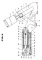
- the preferred embodiment of a seat belt arrangement for a automotive seat includes the preferred embodiment of a belt buckle pre-tensioning device which is designed to retract a seat belt buckle in a belt tightening direction in response to an extraordinary magnitude of inertia moment induced by vehicular abrupt deceleration, such as collision.
- the belt buckle pre-tensioning device includes a buckle anchor plate 1 which is formed with an elongated slot 3 with saw teeth 4 formed along at one longitudinal side peripheral edge.
- the buckle anchor plate 1 is supported on an upper rail 40 which forms guide rail assembly of a seat slide mechanism together with a lower rail 36, by means of an essentially L-shaped supporting bracket 39 and a stand plate 2 which is rigidly fixed to the supporting bracket and extends essentially in vertical direction.
- the belt buckle anchor plate 1 has an essentially U-shaped hooking section 1a at the lower end thereof. The hooking section is engaged with an essentially reversed U-shaped hooking section 38 formed at the rear end of a locking rail 37 which is rigidly fixed on the floor of the vehicular body.
- a seat back reclining device is mounted at the read end portion of a seat cushion frame 44.
- the seat back reclining device includes a base plate 41 and other per se known components of the device.
- the base plate 41 of the seat back reclining device pivotally supports a seat back arm 42 for pivotal movement about a pivot shaft 43.
- a belt buckle 7 is connected to the buckle anchor plate 1 via a connecting plate 6.
- the connecting plate 6 has a toothed projection 5 and connected to the belt buckle via a strap 8 which is rigidly fitted with the connecting member by means of a pivot bolt 11.
- the toothed projection 5 disposed in the elongated slot 3.
- the toothed projection 5 normally engages its teeth with the saw teeth 4 formed on the longitudinal peripheral edge of the slot.
- the toothed projection 5 extends or projects from the surface of the connecting plate 6 opposing to the buckle anchor plate 1.
- the width of the toothed projection 5 is formed smaller that the width of the elongated slot 3 so as to permit the lateral shift of the toothed projection transverse to the longitudinal axis of the slot.
- the connecting plate 6 has side edge portions 6a mating with the buckle anchor plate 1 and thus serving as guide for transverse movement of the toothed projection 5.
- the lateral shifting causes disengagement of the teeth of the toothed projection 5 from the saw teeth 3 of the elongated slot for permitting longitudinal movement of the connecting plate 6 carrying the belt buckle 7 along the longitudinal axis of the slot.
- An essentially T-shaped actuation lever 9 has one leg formed with an elongated connection slot 10.
- the pivot bolt 11 connecting the strap 8 to the connecting plate 6 extends through the elongated connection slot 10 in a manner to permit pivotal movement of the actuation lever 9 thereabout.
- Another leg which extends in alignment with the aforementioned one leg has an end connected to the stand plate 2 by means of a pivot shaft 12 in pivotal fashion.
- the pivot shaft 12 forms stationary pivot for the actuation lever 9.
- the other leg which extends in transverse with respect to the remaining legs, is connected to a mechanical actuator.
- the mechanical actuator includes an actuator cylinder 19 in which is disposed a bias compression spring 21.
- a spring seat member 14 is provided for closing one end of the actuation cylinder 19 oriented in the vicinity of the actuation lever 9.
- the spring seat member 14 is connected to the transversely extending leg of the actuation lever via a pivot 13.
- the spring seat member 14 is also connected to a guide rod 15 which extends through the actuator cylinder 9.
- the guide rod 15 is formed with a larger diameter section 15a sliding seated on a guide ring 20 which is provided at the other end of the actuation cylinder 9 oriented remote from the actuation lever 9.
- a circumferential extending groove 17 is formed on the larger diameter section 15a of the guide rod 15.
- a locking lever 24 is provided adjacent the outer end of the guide rod 15 extending from the actuator cylinder 19.
- the locking lever 24 has a locking hook 28 engageable with the circumferential groove 17 for locking the latter at the normal position. While the guide rod 15 is locked by engagement of the locking hook 28 and the circumferential groove 17, the spring seat member 14 is placed on the associated end of the actuation cylinder 19. At this position, the bias compression spring 20 is compressed between the radially extending section of the guide ring 20 and the spring seat member 14 in compressed fashion to accumulate spring force.
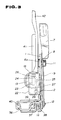
- the locking lever 24 is disposed with a sensor casing 22 which is rigidly secured on the stand plate 2.
- the locking lever 24 is pivotally supported in the sensor casing 22 by means of a pivot 23.
- the locking lever 24 is cooperated with a sensor lever 27 via a connecting pin 26.
- the sensor lever 27 is pivotally supported in the sensor casing 22 via a pivot 25.
- the sensor lever 27 has an end 30 connected to a sensor mass body 29.
- the sensor mass body 29 is provided a predetermined mass weight and loaded at a normal position by means of set springs 31 and 32.
- the sensor mass body 29 is disposed in the sensor casing 22 with orienting its longitudinal axis in parallel to the longitudinal axis of the vehicular body for sensing longitudinal acceleration exerted on the vehicle.
- Set spring 32 is provided a spring force corresponding a set magnitude of inertia moment so as to permit axial movement of the sensor mass body 29 in frontward direction when the longitudinally exerted inertia moment is greater than a predetermined deceleration criterion.
- An externally accessible adjuster screw 33 extends through the sensor casing 22.
- a conical adjuster head 34 is fitted on the inner end of the adjuster screw 33.
- the adjuster head 34 is placed in contact with the rounded end of the sensor lever 27 for adjusting the initial position of the sensor lever.
- the guide rod 15 is normally locked at the position shown in Figs. 1 and 2.
- the spring seat member 14 is rigidly fitted onto the axial end of the actuator housing 19. Therefore, the actuator lever 19 is locked for maintaining the engagement of the toothed projection 5 of the connecting plate 6 and the saw teeth 3 of the elongated slot 4 at the upper end of the elongated slot as shown.
- the sensor mass body 29 shifts frontwardly with overcoming the spring force of the set spring 32. Since the sensor lever 27 is connected to the sensor mass body 29 at the end 30, the sensor lever 27 is pivoted in clockwise direction about the pivot 25. Accordingly, the locking lever 24 which is connected to the sensor lever 27 via the connection pin 26, is pivoted about the pivot 23 to disengage the locking hook 28 from the circumferential groove 17 of the guide rod 15. Therefore, the guide rod 15 becomes free from restriction. The bias compression spring 21 then becomes active with the pre-loaded spring force to explosively or instantly kick of the spring seat member 14 outwardly. As a result. the actuation lever 9 is swiftly pivoted in clockwise direction to release engagement between the toothed projection 5 and the saw teeth 4 and to shift the connecting plate 6 with the toothed projection to the lower end of the slot 3.
- the foregoing action of the belt buckle pre-tensioning device is performed in cooperation with an emergency locking seat belt retractor to causing locking of extraction of the seal belt webbing.
- Both of the seat belt retractor and the belt buckle pre-tensioning device act substantially at simultaneous timing. Therefore, the extracted belt length is shortened in a magnitude of the stroke of movement of the buckle as retracted by the belt buckle pre-tensioning device. As a result, the force tying the seat occupant on the vehicular seat is increased for satisfactorily and safely securing the seat occupant.
- the buckle anchor plate for connecting the belt buckle onto the vehicular body is utilized as a locking plate for the belt buckle pre-tensioning device, locking plate independent of the buckle anchor plate can be neglected. Furthermore, in the shown construction, since the actuator assembly and the sensor are protruded toward inside, i.e. into the seat cushion, interference with other vehicular structural components, such as console box, can be successfully avoided.
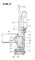
- the seat belt arrangement according to the present invention is applicable not only in combination with the specific construction of the seat slide rail assembly.
- the buckle anchor plate 1 can be mounted on the base plate 41 of the seat back reclining arrangement.
- the buckle anchor plate 1 is rigidly secured on the base plate 41 by means of a plurality of rivets 2a with spacer collars 2b in spaced apart relationship with the base plate. Remaining construction is substantially the same as that in the foregoing embodiment. Therefore, the detailed discussion will be neglected for avoiding redundant discussion.
Landscapes
- Engineering & Computer Science (AREA)
- Mechanical Engineering (AREA)
- Automotive Seat Belt Assembly (AREA)
Applications Claiming Priority (8)
| Application Number | Priority Date | Filing Date | Title |
|---|---|---|---|
| JP253454/89 | 1989-09-28 | ||
| JP253452/89 | 1989-09-28 | ||
| JP1253454A JPH03114948A (ja) | 1989-09-28 | 1989-09-28 | シートベルト装置 |
| JP113826/89 | 1989-09-28 | ||
| JP11382689U JPH0351657U (de) | 1989-09-28 | 1989-09-28 | |
| JP1253453A JPH03114947A (ja) | 1989-09-28 | 1989-09-28 | シートベルト装置 |
| JP1253452A JPH03114946A (ja) | 1989-09-28 | 1989-09-28 | シートベルト装置 |
| JP253453/89 | 1989-09-28 |
Publications (1)
| Publication Number | Publication Date |
|---|---|
| EP0420664A1 true EP0420664A1 (de) | 1991-04-03 |
Family
ID=27470115
Family Applications (1)
| Application Number | Title | Priority Date | Filing Date |
|---|---|---|---|
| EP90310636A Withdrawn EP0420664A1 (de) | 1989-09-28 | 1990-09-28 | Spannvorrichtung für Sicherheitsgurte in Kraftfahrzeugen |
Country Status (2)
| Country | Link |
|---|---|
| US (1) | US5152552A (de) |
| EP (1) | EP0420664A1 (de) |
Cited By (6)
| Publication number | Priority date | Publication date | Assignee | Title |
|---|---|---|---|---|
| EP0573741A1 (de) * | 1992-06-06 | 1993-12-15 | Bayerische Motoren Werke Aktiengesellschaft | Dreipunktsicherheitsgurtsystem für Kraftfahrzeuge |
| US5280954A (en) * | 1991-07-24 | 1994-01-25 | Mercedes-Benz Ag | Inflatable impact protection cushion |
| US5290062A (en) * | 1991-02-20 | 1994-03-01 | Trw Repa Gmbh | Pretensioner in a safety belt system for vehicles |
| GB2320886A (en) * | 1996-12-27 | 1998-07-08 | Nhk Spring Co Ltd | Seat belt tensioning device |
| RU2116902C1 (ru) * | 1995-08-15 | 1998-08-10 | Акционерное общество "НОРМА" | Устройство для упреждающего натяжения лямки ремня безопасности транспортного средства |
| FR2780689A1 (fr) * | 1998-07-06 | 2000-01-07 | Faure Bertrand Equipements Sa | Ancrage pour ceinture de securite, et siege de vehicule comportant un tel ancrage |
Families Citing this family (20)
| Publication number | Priority date | Publication date | Assignee | Title |
|---|---|---|---|---|
| DE59101723D1 (de) * | 1991-02-05 | 1994-06-30 | Trw Repa Gmbh | Rückstrammvorrichtung in einem Sicherheitsgurtsystem für Fahrzeuge. |
| DE4232569C2 (de) * | 1992-09-29 | 1995-10-05 | Autoflug Gmbh | Pyrotechnische Sicherheitsgurt-Strammvorrichtung |
| FR2758503B1 (fr) * | 1997-01-23 | 1999-03-26 | Faure Bertrand Equipements Sa | Siege de vehicule automobile incluant un pretensionneur pour ceinture de securite |
| DE10011829C2 (de) * | 1999-03-15 | 2002-08-08 | Nhk Spring Co Ltd | Stellantrieb für ein Fahrzeuginsassenrückhaltesystem |
| US6604599B2 (en) | 1999-03-15 | 2003-08-12 | Nhk Spring Co., Ltd. | Anti-submarine vehicle occupant restraint system |
| DE10041827B4 (de) * | 2000-08-25 | 2008-02-07 | C. Rob. Hammerstein Gmbh & Co. Kg | Fahrzeugsitz mit einem Sitzträger und mit einem an diesem Sitzträger positionierten Gurtschloss eines Sicherheitsgurtes |
| EP1199214B1 (de) | 2000-10-13 | 2006-06-21 | Nhk Spring Co.Ltd. | Rückhaltesystem mit Vorrichtung zur Verhinderung des Abtauchens eines Fahrzeuginsassen |
| DE20208808U1 (de) * | 2002-06-06 | 2002-10-17 | TRW Occupant Restraint Systems GmbH & Co. KG, 73553 Alfdorf | Vorrichtung zum Straffen eines Sicherheitsgurts |
| US7513843B2 (en) * | 2005-04-18 | 2009-04-07 | Borgwarner Inc. | Mechanical chain tensioner with ratcheting device |
| US7455606B2 (en) * | 2005-06-08 | 2008-11-25 | Borgwarner Inc. | Mechanical chain tensioner with a rotational ratcheting device |
| US20070228787A1 (en) * | 2006-04-04 | 2007-10-04 | Said Nakhla | Harness pretensioning device for child safety seat |
| US20100089177A1 (en) * | 2006-11-30 | 2010-04-15 | Waite Daryn L | Tensioner sensor (bts) |
| US20110285115A1 (en) * | 2010-05-24 | 2011-11-24 | Gm Global Technology Operations, Inc. | Roof Rail Side Air Bag With Tensioning Tether |
| JP6574616B2 (ja) * | 2015-06-03 | 2019-09-11 | シロキ工業株式会社 | 車両用シートのスライド装置 |
| JP6341893B2 (ja) * | 2015-07-22 | 2018-06-13 | 株式会社東海理化電機製作所 | バックル装置 |
| US9821758B2 (en) * | 2016-02-05 | 2017-11-21 | Ford Global Technologies, Llc | Pretensioning, force-limiting seat belt assembly |
| US9827947B2 (en) | 2016-02-10 | 2017-11-28 | Ford Global Technologies, Llc | Load limiting seat belt buckle assemblies |
| JP6822201B2 (ja) * | 2017-02-17 | 2021-01-27 | トヨタ紡織株式会社 | 乗物シート用クッションフレーム |
| US11027696B2 (en) | 2019-04-17 | 2021-06-08 | Toyota Motor Engineering & Manufacturing North America, Inc. | Vehicle seat belt systems |
| KR20250022436A (ko) * | 2023-08-08 | 2025-02-17 | 현대자동차주식회사 | 시트벨트 장치 및 그 장착방법 |
Citations (4)
| Publication number | Priority date | Publication date | Assignee | Title |
|---|---|---|---|---|
| DE3631780A1 (de) * | 1985-09-20 | 1987-04-02 | Toyota Motor Co Ltd | Sitzschiene mit eingebautem gurtanker |
| EP0300469A1 (de) * | 1987-07-21 | 1989-01-25 | Autoliv-Kolb GmbH & Co. | Gurtstrammer für Fahrzeugsicherheitsgurte |
| DE3807928A1 (de) * | 1988-03-10 | 1989-09-21 | Daimler Benz Ag | Fahrzeugsitz mit einem sicherheitsgurt |
| DE3822253A1 (de) * | 1988-07-01 | 1990-01-04 | Bayerische Motoren Werke Ag | Spannvorrichtung fuer sicherheitsgurte in kraftfahrzeugen |
Family Cites Families (6)
| Publication number | Priority date | Publication date | Assignee | Title |
|---|---|---|---|---|
| GB8504452D0 (en) * | 1985-02-21 | 1985-03-27 | Autoliv Dev | Seat belt pre-tensioning device |
| US4669782A (en) * | 1985-09-20 | 1987-06-02 | Toyota Jidosha Kabushiki Kaisha | Belt anchor incorporating seat track structure |
| JPH0439084Y2 (de) * | 1985-12-09 | 1992-09-11 | ||
| GB8608134D0 (en) * | 1986-04-03 | 1986-05-08 | Autoliv Dev | Seat belt pre-tensioning device |
| AU607789B2 (en) * | 1987-08-01 | 1991-03-14 | Britax-Kolb Gmbh & Co. | Acceleration sensor for safety systems and/or seat belt systems in motor vehicles |
| DE3729505A1 (de) * | 1987-09-03 | 1989-03-23 | Bsrd Ltd | Vorrichtung zum straffen eines sicherheitsgurtes eines fahrzeugs, insbesondere kraftfahrzeugs |
-
1990
- 1990-09-25 US US07/588,008 patent/US5152552A/en not_active Expired - Fee Related
- 1990-09-28 EP EP90310636A patent/EP0420664A1/de not_active Withdrawn
Patent Citations (4)
| Publication number | Priority date | Publication date | Assignee | Title |
|---|---|---|---|---|
| DE3631780A1 (de) * | 1985-09-20 | 1987-04-02 | Toyota Motor Co Ltd | Sitzschiene mit eingebautem gurtanker |
| EP0300469A1 (de) * | 1987-07-21 | 1989-01-25 | Autoliv-Kolb GmbH & Co. | Gurtstrammer für Fahrzeugsicherheitsgurte |
| DE3807928A1 (de) * | 1988-03-10 | 1989-09-21 | Daimler Benz Ag | Fahrzeugsitz mit einem sicherheitsgurt |
| DE3822253A1 (de) * | 1988-07-01 | 1990-01-04 | Bayerische Motoren Werke Ag | Spannvorrichtung fuer sicherheitsgurte in kraftfahrzeugen |
Cited By (8)
| Publication number | Priority date | Publication date | Assignee | Title |
|---|---|---|---|---|
| US5290062A (en) * | 1991-02-20 | 1994-03-01 | Trw Repa Gmbh | Pretensioner in a safety belt system for vehicles |
| US5280954A (en) * | 1991-07-24 | 1994-01-25 | Mercedes-Benz Ag | Inflatable impact protection cushion |
| EP0573741A1 (de) * | 1992-06-06 | 1993-12-15 | Bayerische Motoren Werke Aktiengesellschaft | Dreipunktsicherheitsgurtsystem für Kraftfahrzeuge |
| US5431448A (en) * | 1992-06-06 | 1995-07-11 | Bayerische Motoren Werke Ag | Three-point safety belt system for motor vehicles |
| RU2116902C1 (ru) * | 1995-08-15 | 1998-08-10 | Акционерное общество "НОРМА" | Устройство для упреждающего натяжения лямки ремня безопасности транспортного средства |
| GB2320886A (en) * | 1996-12-27 | 1998-07-08 | Nhk Spring Co Ltd | Seat belt tensioning device |
| GB2320886B (en) * | 1996-12-27 | 2001-04-11 | Nhk Spring Co Ltd | Seat belt pre-tensioner assembly |
| FR2780689A1 (fr) * | 1998-07-06 | 2000-01-07 | Faure Bertrand Equipements Sa | Ancrage pour ceinture de securite, et siege de vehicule comportant un tel ancrage |
Also Published As
| Publication number | Publication date |
|---|---|
| US5152552A (en) | 1992-10-06 |
Similar Documents
| Publication | Publication Date | Title |
|---|---|---|
| US5152552A (en) | Emergency tensioning device for automotive seat belt | |
| US5374110A (en) | Pretensioner for seat belts | |
| KR100925574B1 (ko) | 시트 벨트 프리텐셔닝 장치 | |
| EP0264016A2 (de) | Sitzeinheit mit Insassenrückhaltevorrichtung | |
| EP1344697A2 (de) | Gurtstraffer für Kraftfahrzeugsitze | |
| US6902195B2 (en) | Seat belt pretensioner | |
| US5288105A (en) | Safety belt system with emergency retraction capability | |
| US5129679A (en) | Locking device and vehicle safety belt tightening apparatus | |
| EP0655371A1 (de) | Gurtstrammer für Sicherheitsgurte | |
| KR100616008B1 (ko) | 차량의 시트벨트 | |
| US4864086A (en) | Vehicle deceleration sensor | |
| US6205628B1 (en) | Buckle | |
| US6186431B1 (en) | Belt retractor for a vehicular seat belt system | |
| US4343488A (en) | Seat belt system with reduced spooling | |
| JP2008507450A (ja) | シートベルト用プリテンショナー | |
| WO2007071522A1 (en) | Seat belt apparatus | |
| US5374080A (en) | Safety belt pretensioner for safety belt systems in vehicles | |
| JPH06270762A (ja) | プリテンショナー | |
| US5165718A (en) | Sensor for seat belt pretensioner | |
| KR100228123B1 (ko) | 안전띠의 장력조절장치 | |
| JPH03114948A (ja) | シートベルト装置 | |
| JPH03114946A (ja) | シートベルト装置 | |
| KR100456543B1 (ko) | 자동차용 헤드 레스트 구조 | |
| JPH03114947A (ja) | シートベルト装置 | |
| KR100318237B1 (ko) | 차량의 시트 벨트 |
Legal Events
| Date | Code | Title | Description |
|---|---|---|---|
| PUAI | Public reference made under article 153(3) epc to a published international application that has entered the european phase |
Free format text: ORIGINAL CODE: 0009012 |
|
| AK | Designated contracting states |
Kind code of ref document: A1 Designated state(s): DE FR GB |
|
| 17P | Request for examination filed |
Effective date: 19910917 |
|
| 17Q | First examination report despatched |
Effective date: 19921214 |
|
| STAA | Information on the status of an ep patent application or granted ep patent |
Free format text: STATUS: THE APPLICATION IS DEEMED TO BE WITHDRAWN |
|
| 18D | Application deemed to be withdrawn |
Effective date: 19940301 |